


Serviços Personalizados
Journal
Artigo
 Inglês (pdf)
 Artigo em XML
 Referências do artigo
 Enviar este artigo por email
Indicadores
-
 Citado por SciELO
 -
 Acessos
Links relacionados
-
 Citado por Google
 -
 Similares em
SciELO
Similares em
SciELO -
 Similares em Google
Compartilhar

 Permalink
Ingeniería e Investigación
versão impressa ISSN 0120-5609
Ing. Investig. vol.35 supl.1 Bogotá dez. 2015
https://doi.org/10.15446/ing.investig.v35n1Sup.53584
DOI: http://dx.doi.org/10.15446/ing.investig.v35n1Sup.53584
A new monitoring and characterization system of partial discharges based on the analysis of the spectral power
Un nuevo sistema de monitorización y caracterización de descargas parciales basado en el análisis de la potencia espectral
J.A. Ardila-Rey1, R. Albarracin2, G. Robles3, and J.M. Martínez-Tarifa4
1 Jorge Alfredo Ardila Rey: Mechatronic Engineer, Universidad de Pamplona, Colombia. Ph.D. in Electrical, Electronic and Automatic Engineering, Universidad Carlos III de Madrid, España. Affiliation: Full time Academic at Universidad Técnica Federico Santa María, Chile.
E-mail: jorge.ardila@usm.cl
2 Ricardo Albarracín Sánchez: Electrical engineer, Universidad Carlos III de Madrid, España. Ph.D. in Electrical, electronic and automatic Engineering, Universidad Carlos III de Madrid, Spain. Affiliation: Technological vigilance responsible, Boslan Ingeniería Consultoría, Spain.
E-mail: rasbarracin@gmail.com
3 Guillermo Robles: Electronic Engineer, Universidad Pontificia de Comillas, Spain. Ph.D. in Electronic Engineering, Universidad Pontificia de Comillas, Spain. Affiliation: Full time professor at Universidad Carlos III de Madrid, Spain.
E-mail: grobles@ing.uc3m.es
4 Juan Manuel Martínez Tarifa, Electrical engineer, Universidad de Granada, España. Ph.D. en in Electrical, electronic and automatic Engineering, Universidad Carlos III de Madrid, Spain. Affiliation: Full time professor at Universidad Carlos III de Madrid, Spain.
E-mail: jmmtarif@ing.uc3m.es
How to cite: Ardila-Rey, J.A., Albarracín, R., Robles, G., & Martínez-Tarifa, J.M. (2015). A new monitoring and characterization system of partial discharges based on the analysis of the spectral power. Ingeniería e Investigación, 35(Supl)/ 13-20. DOI: http://dx.doi.org/10.15446/ing.investig.v35n1Sup.53584
ABSTRACT
Partial Discharges (PD) are one of the possible causes for unexpected faults in power systems equipment, so that its measure is an essential tool for high-voltage electrical equipment maintenance. In order to characterize the PD activity, some statistic magnitudes are necessary. For this reason, the acquisition and processing of PD is very important when making critical decisions regarding disconnection or repairing assets in power systems. On the other hand, the measurement environments often present multiple sources of electrical noise, thus the proper interpretation of PD patterns is a challenge in the identification of sources of different nature. In this paper, the development of a PD monitoring system capable of displaying in real time the classic PD parameters, the PD waveform, its frequency spectrum and calculating statistical parameters of the acquisition, are presented. On the whole, a new method of identifying sources of PD and electrical noise, developed by the authors, which is based on measuring the relative spectral power of PD pulses, is shown. This method has proven effective in characterizing PD and electrical noise; a series of experiments conducted in several test objects are presented in order to validate the performance of the proposed system.
Keywords: Partial discharges, electrical insulation, PD pulse waveform, spectral power, fast Fourier transform.
RESUMEN
Las descargas parciales (PD) son responsables de las fallas inesperadas en los equipos de sistemas de potencia, por lo que su medida es una herramienta fundamental en el mantenimiento de equipos eléctricos de Alta Tensión. Con el fin de caracterizar la actividad de PD, algunas magnitudes estadísticas son necesarias. Por esta razón, la adquisición y procesamiento de PD es muy importante en el momento de tomar decisiones críticas en relación con la desconexión o reparación de los sistemas de potencia. Por otro lado, los entornos de medida suelen tener presentes múltiples focos de ruido eléctrico, por lo que la interpretación adecuada de patrones de PD es un reto al que se añade la identificación de fuentes de diferente naturaleza. En este artículo se presenta el desarrollo de un sistema de monitorización de descargas parciales, capaz de visualizar en tiempo real los parámetros clásicos de descargas parciales, la forma de onda de un pulso de PD, su espectro de frecuencia y calcular los parámetros estadísticos de la adquisición. Conjuntamente se presenta un nuevo método de identificación de fuentes de PD y ruido eléctrico que han desarrollado los autores, el cual se basa en la medida de la potencia espectral relativa de los pulsos de PD. Éste método ha probado ser eficiente en la caracterización de PD y ruido eléctrico, Una serie de experimentos realizados en varios objetos de ensayo son presentados, con el fin de validar el comportamiento del sistema propuesto.
Palabras clave: Descargas parciales, aislamiento eléctrico, forma de onda de los pulsos de PD, potencia espectral, transformada rápida de Fourier.
Received: September 15th 2015 Accepted: October 10th 2015
Introduction
As it is widely known, harmonics and transients phenomena that may occur at electricity generation, transmission and even distribution networks can cause fluctuations in power quality.
These fluctuations can accelerate the aging mechanisms of insulation systems, causing the permanent loss of their insulating properties and, therefore, their complete breakdown (Bahadoorsingh and Rowland, 2007; Cavallini, Fabiani, Mazzanti, & Montanari 2000). It is also very important not to exceed the nominal values of voltage in order to avoid the direct breakdown of the insulation system. This is because PD may occur in the power cables and electrical machines, even at nominal voltages. These discharges are a degradation phenomenon with low energy taking place in regions of high-electric and nonhomogeneous field divergence within the dielectric sections.
PD activity does not cause immediate failure, but contributes to the deterioration of the insulation system due to chemical degradation and physical attack by electron-ion bombardment that occurs inside the solid insulating material. This leads to premature failure in electrical equipment as these events can occur several times per network cycle. Partial discharges can also be the result of other environmental degradation mechanisms, such as thermals or mechanicals (Kreuger, 1989; Stone, 1993 and Morshuis, 1993).
For these reasons, PD measurement has become one of the main insulation diagnostic methods used in predictive maintenance and condition-based maintenance (CBM) of electric machines, in order to establish system degradation isolation, since their lifetime is determined by the degree of insulation aging. The main advantages of partial discharge measurements are:
- Ability to detect severe abnormalities resulting of multiple mechanisms of aging insulation.
- Applicability to different assets. The same technology is used to measure the insulation in transformers and electric motors.
- Ability to make measurements with the machine in service (online monitoring).
Traditionally, most commercial measurement systems represent PD activity as pulses (in pC or mV) superimposed on a diagram of the network signal. These plots are called Phase-Resolved Partial Discharge Patterns, or PRPD Patterns, that help to classify PD sources (corona, internal and surface). The importance of this standard of PD representation, is the possibility to identify some sources of discharges which could be harmful or not for the insulation system.
Because of the stochastic behavior of PD, their properties are described in terms of time-dependent random variables and parameters should be treated statistically (Krivda, 1995 and Lapp & Kranz, 2000).
Since the PD detection is usually done in industrial environments, where electrical noise is present, it is necessary to apply advanced techniques of separation and noise rejection for proper measurement and interpretation of PD. This is especially important in the case of using this technique with the machine in operation. Following this trend, the analysis of the waveform of the pulse PD is also used for separating partial discharges from electrical noise and even to classify different PD sources (Okubo & Hayakawa, 2005; Cavallini, Montanari, Contin & Pulletti, 2003; Robles, Martinez-Tarifa, Rojas-Moreno & Sanz-Feito 2009).
In this paper, the design and implementation of a new system for PD monitoring is presented, which allows viewing of PRPD patterns (cp phase angle versus amplitude of discharge), the waveform and the frequency spectrum of the pulses in real time and to perform the calculation of the statistical parameters of the signals during measurement. Additionally, a new method of separation and classification of PD and electrical noise, which has been developed by the authors, is described. This method is also embedded in the monitoring system described below.
Experimental setup
The detection circuit used for the PD acquisition system presented in this work, is based on the IEC 60270 standard and corresponds to the indirect detection circuit shown in Figure 1 (IEC-60270, 2000). In this case, a high-frequency current transformer (HFCT) is used (bandwidth between 3 MHz and 80 MHz) for measuring partial discharge pulses.
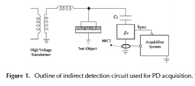
For this configuration, a high-voltage source feeds two branches: in the first one, the test object in which the PD occur is located, and in the second one, a capacitive divider formed by a coupling capacitor Ck and a quadrupole, or an impedance ZM, which provides a sinusoidal signal of 50 Hz in synchronism phase to the voltage supplied by the high-voltage source is connected. In the path ground, the HFCT transducer, which measures the transient currents, sends this information to the data acquisition board attached to the system.
The system used for the acquisition and processing of the pulses consists of a NI-PXIe-1082 chassis, an acquisition board NI-PXI-5124 with a sampling frequency of 200 MS/s and a resolution of 12-bit, and a controller NI-PXIe-8115 with a dual-core i5-2510E processor with 2 GB of RAM. The sync signal is inserted in the card channel "0", while PD pulses are connected to channel "1".
In order to validate the proposed monitoring system, a PD activity was established, in a controlled manner, by applying high-voltage to various test objects; three of them are shown in Figure 2.
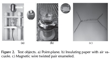
Point-plane configuration: In this particular case, a needle of 0.5 mm in thickness is placed 1 mm above a metallic ground plane, in order to obtain corona partial discharge type, due to the presence of a highly divergent electric field (Figure 2a). The metallic plane is covered with an insulating film to prevent a total insulation breakdown.
Insulating paper with air vacuole: Several layers of insulating paper slot of rotary machines, 0.35 mm thick, vacuum packed are taken. This set is immersed in typical mineral oil of a power transformer (to avoid surface discharges at low voltage) and placed between two metal electrodes (Figure 2b). The 5 core sheets were pierced by a needle of 1mm diameter, in order to create a cylindrical vacuole with a height of 1.75 mm, which ensures the occurrence of internal PD.
Twisted pair of enameled magnet wire: In this test object (Figure 2c), it is very common to find similar surface PD occurring in the electric insulation between windings in electrical rotating machines (Stone & Kapler, 1998).
Statistical analysis and data processing PD
Weibull probability distribution
Partial discharges are a stochastic phenomenon; so far, only one event is not significant. This is why the parameters associated with the detected pulse should be treated statistically. In the case of the analysis of magnitudes, the most common tool to characterize them is the Weibull probability distribution P(q), Equation (1) (Stone, 1993; and Lapp & Kranz, 2000).
Where:
P(q) is the probability of having a discharge with an amplitude equal or below q.
Alfa (α) (0 < α < ∞) is the magnitude of discharge reached by 63.2 °% of the pulses (analogous to the meaning of mean of the normal distribution). Its statistical significance loses value at very low P values.
Beta(β) (0<β<∞) shape variable β(0 <β <∞) is a measure of the variability of the PD magnitudes. A small value of β(β<2) is associated with high variability, i.e., there will be much difference between the minimum magnitude of PD and the maximum detected in the test.
Weibull parameters α and β can be calculated using the least squares regression.
In order to estimate the maximum magnitude of PD (associated with the size of the defect in the insulation), it is not possible to use the highest value detected in an acquisition, because it is not statistically representative. Therefore, the maximum amplitude statistics Qmax95 %is used, which defines the magnitude of PD below the 95 °% of all detected.
Additionally, it is very important to know the NW factor, which is the number of discharges detected per cycle (Cacciari, Contin, & Montanari, 1995). This parameter is directly related to the number of imperfections that can cause PD in the insulation.
The analysis of these statistical parameters allows to establish a diagnosis on the state of an insulation system based on the levels of PD detected. And it provides an adequate database for machines with similar nominal voltage, cooling, etc. (Stone, Boutle, Culbert, & Dhirani 2004; Stone & Warren, 2004). Similarly, an anomalous increase in any of these statistic variables may reveal the presence of degradation mechanisms, which can be destructive for electrical insulation (Stone et al., 2004; Stone & Warren, 2004 and Tozzi, Cavallini & Montanari, 2011).
Source separation method based on analysis of the spectral power (PRL-HRP maps)
In previous works, the way in which the spectra of partial discharge pulses change their shape depending on their origin could be verified (Martinez-Tarifa et al., 2010), for the same experimental setup. In order to provide greater statistical reliability to this work, to improve the characterization of pulses for clusters and make their results completely independent from the size or total energy from the source, the authors have proposed a new method of separating PD and noise sources from the relative spectral power of the signals. The essential idea is to calculate the spectral power of the signals detected on two frequency ranges. Subsequently, these values are normalized by dividing the total power of the detected signal (Equations (2) and (3)) and these relative values of power PRL-PRH (Power Ratio for High-Frequencies - Power Ratio for Low-Frequencies) are plotted on a map that is assist of the operator to characterize different phenomena (PD and/or noise) simultaneously appearing in the measurement system.
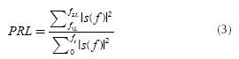
Where:
 is the magnitude of the FFT of the PD pulse signal, s(t).
 is the high-frequency band.
 it is the low-frequency band.
- fT, is the maximum frequency under analysis.
The representation is done on a two dimensional plane, which defines the percentage (%) of high-power and low-power calculated for each signal. Therefore, each detected partial discharge will have a PRH parameter and another PRL value to be located as a point on the map PRL-PRH.
These frequency bands can be chosen by the operator according to the observed spectra.
With respect to the frequency ranges chosen, the following is suggested:
- The sum of two frequency ranges must not cover a whole spectrum analyzed [0, fT], because in that case, information from an axis would be redundant (PRH would equal 100-PRL, and vice versa).
- The intervals can be complementary or overlapping. Depending on whether the first case or the second take place, the points may not be located above or diagonal map.
- It is recommended not to lose the sight of the interval shown, which f1L<f2H*.
It should be noted that the position in the PR plane of a cloud of points cannot be identified, per se, as a source of PD, universally. The detected waveform of a PD is altered by the detection circuit through which it is measured, due to the pulse propagation from the emission source to the measuring point, etc. Therefore, a change in the above conditions will alter the position (and shape) of the cloud of points in the PR map.
This representation does allow to separate sources that are simultaneously active in a single experiment, so that the selection of a cloud of points will have a PRPD pattern associated, which permits proper identification of PD or electrical noise. For more information about this separation method, see (Ardila-Rey, Martínez-Tarifa, Robles & Rojas-Moreno, 2012).
Description of the proposed PD monitoring system
System software
In order to properly characterize and quantify the PD phenomenon, and to get results as a basis for determining whether an equipment should remain in service or not, the PD acquisition system should be able to acquire and store large amounts of data to generate, immediately, accurate PRPD patterns, either for immediate viewing or further analysis (Ardila-Rey, Martínez-Tarifa, Robles & Rojas-Moreno, 2013; Mota & Vasconcelos, 2001).
The software implemented in the monitoring system was designed in order to:
- Display and store real-time classic parameters PD (phase angle φ- amplitude).
- Display the waveform and frequency spectrum of pulses in real time.
- Show a PRL-PRH map for PD source and noise classification and separation. The maps are also updated in real time.
- Provide the ability to display the statistical parameters (total discharges per cycle (N), α, β, Qmax95 %', and NW) of the data, in case of being required by the user.
Additionally, the system can restart at any time, acquiring pulses (PD counter (N) to zero) upon request by the user or when the trigger level, the full scale that displays the PRPD patterns and waveform of PD pulses are changed. Both, the trigger level as well as the full scale, shall be common to the detection of PRPD and waveforms.
The programming tool used for the development of this application is Labview 2012. The internal structure of the code developed is basically formed by 4 stages:
- Acquisition.
- Peak detection.
- Display and storage.
- Signal-processing.
These steps are executed sequentially from stage 1 to stage 3. Stage 4 optionally begins each time, obtaining the statistical parameters of the acquisition that are required.
Acquisition
At this stage, the system is in charge of acquiring the pulses sent by the PD HFCT as ZCD (Zero Crossing Detector) indicates. The ZCD is basically a software routine that detects the change in polarity of the synchronizing signal.
- At this stage the system is set, indicating:
- Instant in which to initiate acquisition actions.
- The type of resolution that supports the card attached to the system.
- The vertical configuration properties (axis of magnitudes) of the acquisition.
- The properties that control the electrical characteristics of the channel as the input impedance.
- The configuration of the properties of the time axis of the acquisition.
- The type of trigger for the synchronization signal.
- The way to deliver the acquired data.
- The time at which the acquisition is completed
Peak detection
The waveform of PD pulses considerably varies depending on the test object, the applied voltage, environmental issues, the sensor type and configuration of the measurement circuit. For this reason, it is important that the acquisition system is flexible enough to avoid misidentification of amplitude, polarity and phase (with respect to applied voltage) of the acquired PD pulses.
When measuring the waveform of the PD pulse with sensors in the HF or VHF range, the peak value of the signal P1 (desired), is accompanied by several cycles (P2, P3, -P4, -P5, y -P6), as shown in Figure 3, to represent PRPD patterns. These peaks of lower amplitude must be ignored taking only into account the higher value, which is to be considered directly related to the displacement of electric charge PD.
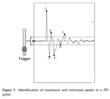
In order to successfully obtain the highest peak amplitude with the polarity and phase for each PD pulse, a detection algorithm capable to process this information as soon as possible, is implemented (bear in mind that the duration of these signals may be in the order of nanoseconds). This algorithm basically consists of two blocks of peak detection, acting simultaneously as shown in Figure 4.
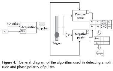
In this scheme, each block is responsible for storing in a volatile matrix the amplitude and time for all the peaks from each PD pulse, during the time of the acquisition window (default values: 0.1 ms, 1 s, 4 microseconds and 10 microseconds) and which in turn are above the trigger level. This threshold is symmetrically set in the main window of the software using the same magnitude to the positive and negative peaks.
Therefore, for the PD pulse in Figure 2, block 1 would store the information of the positive peaks P?, P2 and P3 (in Figure 3), and block 2 the information of negative peaks -P4, -P5 and -P6, in a volatile matrix. Subsequently, with this information the algorithm identifies in the matrix which is the largest amplitude (Pmax), with their respective polarity and phase (φx, referred to as phase sync signal), proceeding to store it in nonvolatile new array.
Data stored in the nonvolatile array (amplitude, polarity and phase) are used in the representation of PRPD patterns and for calculation of statistical parameters. The volatile matrix is deleted once information on each peak PD pulse is obtained, and is updated with the values as follows.
The procedure is performed for all the acquired pulses that exceed the trigger level set. The synchronizing signal, besides allowing the start of acquisition PD pulses, is used by the ZCD to refer the stage times for each peak found, before being stored in the nonvolatile matrix and therefore be correctly located between 0 and 20 ms.
Display and storage
As shown in Figure 5, the representation of the acquired data and calculations performed by the software is done through four graphic displays in the main panel or user interface. A fixed display displays PRPD patterns (pp phase angle, amplitude and polarity), and other 3 selectable displayed waveforms of a PD pulse, frequency spectrum and PRL-PRH map classification and separation of pulses, for the data obtained during the acquisition. All this information is updated in real time.
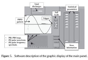
Additionally, a block of data allows to visualize the statistical parameters of the acquisition, whenever required.The software also allows to save a file (.dat or .txt), the PRPD patterns that are displayed on a graphic display and the waveform of each pulse acquired that appears in the PRPD pattern.
PD Experimental results and validation of the PD monitoring system
PRPD patterns and statistical parameters.
For the development of the experiments presented in this section, PD activity was created in a controlled manner by applying high-voltage tests on the objects described in the experimental setup.
Corona PD: In Table 1 and Figure 6, the results obtained for the acquisition system using the point-plane (corona PD) configuration, with a voltage level of 2.8 kV, was observed. As expected, the PRPD shows classical pattern of corona PD produced in the maximum applied voltage, with little dispersion magnitudes detected.
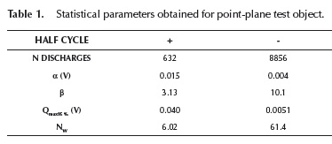
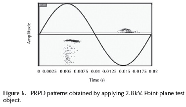
As expected for this type of PD, low statistical dispersion (high β) to each of the pulses obtained in both half cycles, still less for the negative half cycle, was obtained.
Surface PD: The PD inception voltage for twisted pair was about 1.1 kV, showing piercing for not more than 3 kV. For this reason, measurements were made for 1.1 kV. Table 2 and Figure 7 show the statistical parameters and PRPD patterns for the measuring system respectively.
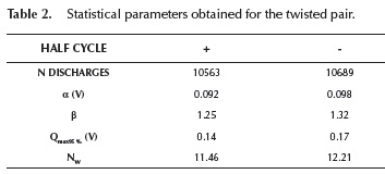
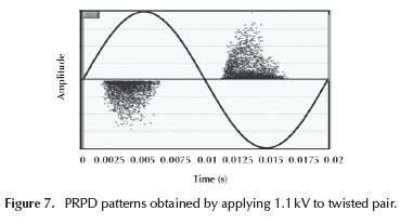
The PRPD pattern in Figure 7 is, as expected for typical PD surface sources, leading to high magnitudes of PD for applied maximum voltages and lower values of β (high statistical dispersion in the registered magnitudes). It is noted that for low values of β, it is not advisable to give valid statistical estimates of magnitude loading (especially α).
Internal PD: In the case of the vacuole created inside the insulating paper sheets of slots for rotary machines, the measurements were made by applying 9.8 kV to the test object described in Figure 2b. The results obtained for this system are shown in Table 3 and Figure 8.
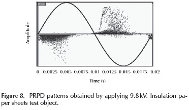
In Figure 8, the typical internal discharges PRPD patterns are observed, where high quantities of PD are concentrated in regions where the voltage applied to the test object has a higher slope.
The fact that the package with the sample is immersed in mineral oil prevents the onset of surface discharges, forcing PD to only appear within the vacuole. From the results in Table 3, one can also appreciate the large statistical dispersion in the magnitudes of detected PD (low values of P), also typical for internal PD.
In Figure 9, PRL-PRH maps associated with each of the PD sources previously described are observed: PD corona (Figure 9a), surface PD (Figure 9b) and internal PD (Figure 9c). The frequency intervals used to characterize each PD sources were: f1L= 0 MHz, f2l = 10 MHz, f1H = 20 MHz, f2H = 29 MHz.
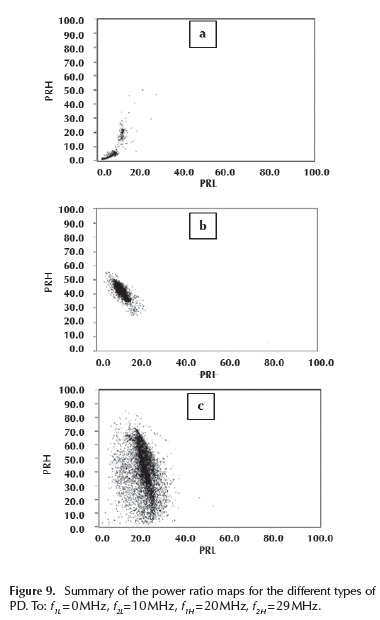
Clearly, each type of PD exhibits different PRL and PRH, and different regions of each classification map are located. This is very important because in case of finding multiple sources acting simultaneously on the same test object, each of the clusters can be clearly identified in order to display the corresponding PRPD.
Characterization of PD and electrical noise in a distribution transformer
In order to evaluate the technique of PD source separation and electrical noise in a more realistic electric asset, a transformer oil-paper insulated (25 kVA, 15 kV/420V) has been used. A voltage of 15 kV between the primary winding and grounded (grounded side) has been applied, in order to verify the presence of a stable PD activity for this voltage level in its insulation system. The results for this experiment are observed in Figure 10.
For this experiment, the intervals used were: f1L = 0 MHz, f2L = 10 MHz, fH = 20 MHz, f2H = 29 MHz.
Figure10a (left) represents the typical PRPD pattern corresponding to electrical noise (uncorrelated phase) obtained in the laboratory by applying 800 V to the test object and a low trigger level. Figure 10a (right) displays the PR map intervals used for the separation described above. On this map, a well-defined cloud of points can be seen near the PRH axis (almost parallel). Because this cloud is on the top of the PR map, the spectral power ratios are higher in the band [20, 29] MHz than those obtained in the lower range [0, 10] MHz.
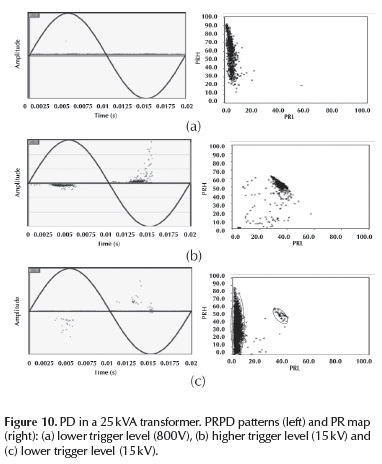
Figure10a (left) represents the typical PRPD pattern corresponding to electrical noise (uncorrelated phase) obtained in the laboratory by applying 800V to the test object and a low trigger level. Figure 10a (right), displays the PR map intervals used for the separation described above. On this map, the cloud of points is again near, almost parallel, to the PRH axis. As before, the spectral power ratios are higher in the band [20, 29] MHz than those obtained in the lower range [0, 10] MHz.
In Figure 10b, the PRPD patterns and PR map for the transformer at a voltage of 15 kV and a high trigger level to reject noise pulses and get only PD pulses, is observed. On the PRL-PRH map a new cloud of homogeneous points can be seen with very low dispersion in the PRL and PRH parameters. This cloud of points is located near the diagonal map with a spectral power distribution in balanced PRL and PRH (almost 50 °% for both).
Data obtained by lowering the trigger level, maintaining the voltage level at 15 kV is shown in Figure 10c. In the PRPD pattern, the noise and PD pulses acting simultaneously are clearly displayed. The PR map is also able to identify two clouds of points similarly located to those seen in Figure 10a (noise) and Figure 10b (PD) positions. Again, noise is clearly characterized as a cloud of points near the PRH axis map.
Conclusions
In this work, a system is devised for monitoring and characterization of partial discharges, capable of displaying PRPD patterns in real-time, the waveform of a PD pulse with its frequency spectrum and the statistical parameters of the acquisition. Additionally, a novel graphical technique for PD pulse characterization, based on the measurement of relative spectral power of these signals is integrated. This new technique has the advantage of being more flexible than other commercial software techniques used in identifying sources, allowing the operator to select intervals of calculation that considers optimal to separate groups the best way as possible. The experiments allowed successfully validate their behavior for the test objects used in the laboratory and for objects more typical of a real environment.
References
Ardila-Rey J. A., Martínez-Tarifa J. M., Robles G., Rojas-Moreno M. V., 2012, A Partial Discharges acquisition and statistical analysis software, IEEE; Instrumentation and Measurement Technology Conf. (MTC), pp.1670-1675. [ Links ]
Ardila-Rey J. A., Martínez-Tarifa J. M., Robles G., Rojas-Moreno M. V., 2013, Partial Discharge and Noise Separation by Means of Spectral-power Clustering Techniques, IEEE Transactions on Electrical insulation, vol. 20, no. 4, pp. 1436-1443. DOI: 10.1109/TDEI.2013.6571466. [ Links ]
Bahadoorsingh S., Rowland S. M., 2007, The role of power quality in electrical treeing of epoxy resin, presented at the IEEE Conference on Electrical Insulation and Dielectric Phenomena, Vancouver, Canada. [ Links ]
Cacciari, M., Contin, A., Montanari, G.C., 1995, Use of a mixed-Weibull distribution for the identification of PD phenomena, Dielectrics and Electrical Insulation, IEEE Transactions on, vol.2, pp.1166-1179. [ Links ]
Cavallini D., Fabiani G., Mazzanti, and Montanari G. C., June 2000, Models for degradation of self-healing capacitors operating under voltage distortion and temperature, presented at the Proceedings of the 6th International Conference on Properties and Applications of Dielectric Materials, Xi'an, China. [ Links ]
Cavallini, A., Montanari, G.C., Contin, A., Pulletti, F., 2003, A new approach to the diagnosis of solid insulation systems based on PD signal inference, Electrical Insulation Magazine, IEEE, vol.19, pp.23-30. DOI: 10.1109/MEI.2003.1 192033. [ Links ]
IEC 60270, 2000, High Voltage Test Techniques. Partial Discharge Measurements, 3a edition. [ Links ]
Kreuger F.H., 1989, Partial Discharge Detection in High-Voltage Equipment Butterworths, Londres, UK. [ Links ]
Krivda, 1995, Recognition of Discharges Discrimination and Classification, Delft Press. [ Links ]
Lapp, A., Kranz, 2000, H.-G., The use of the CIGRE data format for PD diagnosis applications, Dielectrics and Electrical Insulation, IEEE Transactions on, vol.7, pp.102-112. [ Links ]
Martínez-Tarifa J. M., Robles G., Rojas-Moreno M.V. and Sanz-Feito J., 2010, Partial discharge pulse shape recognition using an inductive loop sensor, Measurement Science and Technology, vol 21. DOI: 10.1088/0957-0233/21/10/105706. [ Links ]
Morshuis P., 1993, Partial Discharge Mechanisms, Delft University Press, Netherlands. [ Links ]
Mota, H.O., Vasconcelos, F.H., May 2001, A partial discharge data acquisition system based on programmable digital oscilloscopes, International Instrumentation and Measurement Technology Conference, IMTC 2001, Proceedings of the 18th IEEE, vol.2, pp.994-999 vol.2, Budapest, Hungry. [ Links ]
Okubo, H., Hayakawa, 2005, N., A novel technique for partial dis-charge and breakdown investigation based on current pulse waveform analysis, Dielectrics and Electrical Insulation, IEEE Transactions on, vol.12, pp. 736- 744. [ Links ]
Robles, G., Martinez-Tarifa, J.M., Rojas-Moreno, M.V., Sanz-Feito, J., 2009, Inductive Sensor for Measuring High Frequency Partial Discharges within Electrical Insulation, Instrumentation and Measurement, IEEE Transactions on, vol.58, pp.3907-3913. [ Links ]
Stone, G.C., 1993, The statistics of aging models and practical reality, Electrical Insulation, IEEE Transactions on, vol.28, pp.716-728. [ Links ]
Stone, G., Kapler, J., May 1998, The impact of adjustable speed drive (ASD) voltage surges on motor stator windings, Cement Industry Technical Conference, 1998. 40th Conference Record. 1998 IEEE/PCA, pp.133-138, Rapid City, US. [ Links ]
Stone G., Boutler E.A., Culbert I., and Dhirani H., 2004, Electrical Insulation for Rotating Machines: Design, Evaluation, Aging, Testing and Repair, IEEE Press Series on Power Engineering, Wiley Interscience. [ Links ]
Stone G.C., Warren V., 2004, Effect of Manufacturer, Winding Age and Insulation Type on Stator Winding Partial Discharge Levels, IEEE Electrical Insulation Magazine, Vol. 20, No. 5. DOI: 10.1109/MEI.2004.1342428. [ Links ]
Tozzi M., Cavallini A., Montanari G.C., 2011, Monitoring Off-line and On-line PD Under Impulsive Voltage on Induction Motors - Part 2: Testing, IEEE Electrical Insulation Magazine, Vol. 27, No. 1, pp 14-21. DOI: 10.1109/MEI.2011.5699443. [ Links ]
