


Services on Demand
Journal
Article
 English (pdf)
 Article in xml format
 Article references
 Send this article by e-mail
Indicators
-
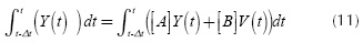
 Cited by SciELO
 -
 Access statistics
Related links
-
 Cited by Google
 -
 Similars in
SciELO
Similars in
SciELO -
 Similars in Google
Share

 Permalink
Ingeniería e Investigación
Print version ISSN 0120-5609
Ing. Investig. vol.35 supl.1 Bogotá Dec. 2015
https://doi.org/10.15446/ing.investig.v35n1Sup.53618
DOI: http://dx.doi.org/10.15446/ing.investig.v35n1Sup.53618
Analytical and experimental discussion of a circuit-based model for compact fluorescent lamps in a 60 Hz power grid
Discusión analítica y experimental de un modelo circuital para luminarias tipo cfl en una red de 60 Hz
G. Malagon-Carvajal1, J. Bello-Peña2, G. Ordóñez3, and C. Duarte4
1 Gabriel Malagon Carvajal: MSc Universidad Industrial de Santander (UIS), Affiliation: PhD Student, UIS, Colombia. Grupo de Investigación en Sistemas de Energía Eléctrica, GISEL, Colombia.
E-mail: gabriel.malagon@correo.uis.edu.co
2 Jeisson Bello Peña: Electrical Engineer, Universidad Industrial de Santander (UIS), Affiliation: Joven Investigador e Innovador- Colciencias, UIS, Colombia. Grupo de Investigación en Sistemas de Energía Eléctrica, GISEL, Colombia.
E-mail: jeisson.bello@correo.uis.edu.co
3 Gabriel Ordóñez Plata: Doctor Ingeniero Industrial, Universidad Pontificia de Comillas-UPCO, España. Affiliation: Titular Professor Laureate, Universidad Industrial de Santander, Colombia. Grupo de Investigación en Sistemas de Energía Eléctrica, GISEL, Colombia.
E-mail: gaby@uis.edu.co
4 Cesar Duarte Gualdrón: PhD, University of Delaware, USA. Affiliation: Associate Professor, Universidad Industrial de Santander, Colombia. Grupo de Investigación en Sistemas de Energía Eléctrica, GISEL, Colombia.
E-mail: cedagua@uis.edu.co
How to cite: Malagon-Carvajal, G., Bello-Pena, J., Ordonez, G., Duarte, C. (2015). Analytical and experimental discussion of a circuit-based model for compact fluorescent lamps in a 60 Hz power grid. Ingeniería e Investigación, 35(Sup1), 89-97. DOI: http://dx.doi.org/10.15446/ing.investig.v35n1Sup.53618
ABSTRACT
This article presents an analysis and discussion on the performance of a circuit-based model for Compact Fluorescent Lamps (CFL) in a 120V 60 Hz power grid. This model is proposed and validated in previous scientific literature for CFLs in 230V 50 Hz systems. Nevertheless, the derivation of this model is not straightforward to follow and its performance in 120V 60 Hz systems is a matter of research work. In this paper, the analytical derivation of this CFL model is presented in detail and its performance is discussed when predicting the current of a CFL designed to operate in a 120V 60 Hz electrical system. The derived model is separately implemented in both MATLAB® and ATP-EMTP® software using two different sets of parameters previously proposed for 230V 50 Hz CFLs. These simulation results are compared against laboratory measurements using a programmable AC voltage source. The measurements and simulations considered seven CFLs 110/127V 60 Hz with different power ratings supplied by a sinusoidal (not distorted) voltage source. The simulations under these conditions do not properly predict the current measurements and therefore the set of parameters and/or the model itself need to be adjusted for 120V 60 Hz power grids.
Keywords: CFL circuit-based model, harmonics attenuation, harmonics diversity, harmonic load modelling.
RESUMEN
En este artículo se presenta un análisis y una discusión sobre el comportamiento de un modelo circuital para lámparas fluorescentes compactas (CFL) en una red eléctrica de 120V 60 Hz. Este modelo es propuesto y validado en trabajos previos para lámparas fluorescentes compactas en sistemas de 230V 50 Hz. Sin embargo, la derivación de este modelo no es fácil de seguir y su desempeño en una red de 120V 60 Hz es materia de investigación. En este trabajo, la derivación analítica de este modelo de CFL se presenta en detalle y se discute su desempeño en la predicción de la corriente consumida por una CFL en un sistema eléctrico de 120V 60 Hz. El modelo derivado es implementado tanto en MATLAB® como en ATP-EMTP®, utilizando dos diferentes conjuntos de parámetros previamente propuestos para lámparas fluorescentes compactas en 230V 50 Hz. Estos resultados de simulación se comparan con mediciones de laboratorio obtenidas utilizando una fuente de tensión alterna programable. Las mediciones y simulaciones consideran siete lámparas fluorescentes compactas 110/127V 60 Hz con diferentes potencias alimentadas por una fuente de tensión sinusoidal (no distorsionada). Las simulaciones bajo estas condiciones no predicen adecuadamente las mediciones realizadas y por lo tanto el conjunto de parámetros y/o el modelo necesitan ser ajustados para redes eléctricas de 120V 60 Hz.
Palabras clave: Modelo circuital CFL, atenuación de armónicos, diversidad de armónicos, modelos de carga armónica.
Received: September 10th 2015 Accepted: October 10th 2015
Introduction
The constant increase of non-linear loads in low voltage grids, specifically the mass adoption of Compact Fluorescent Lamps (CFLs) and Light-Emitting Diode (LED) based lamps, aimed at reducing power demand and improving energy efficiency in lighting systems, has led to high levels of harmonic content in the current drawn from the supply system (Blanco & Parra, 2011) (Romero, Zini, & Ratta, 2011) (Ribeiro, et al., 2011). Therefore, the search for more and better models to assess and predict the collective harmonic impact of these loads on the low voltage network is currently a research topic (Salles, Jiang, Xu, Freitas, & Mazin, Oct. 2012). Moreover, several serious problems are caused by the harmonic currents flowing in the power system: overheating and overloading of conductors (especially neutrals), motors and transformers (increased losses); poor power factor and overloaded capacitor banks; undesired protection tripping and skin effect in conductors (Malagon-Carvajal, Ordonez-Plata, Giraldo-Picon, & Chacon-Velasco, 2014), among others. Considering these facts, there is an urgent need for better models that allow assessing, on the short and medium time scales, the potential impact of nonlinear lighting loads in 120V 60 Hz low voltage distribution networks. The first section of this paper presents some scientific literature related with diversity and attenuation, as well as a review of nonlinear loads models. The next section describes each of the parameters involved in the CFL circuit-based model. The model was originally developed for 230V 50 Hz electrical systems and in this paper there is a discussion on whether it performs well for 120V 60 Hz grids. Then, in the study case, the current estimated by the circuit-based model is compared with measurements from CFLs with sinusoidal voltage supply and different rated powers.
Preliminaries and Previous Work
The CFL loads induce highly distorted currents due to the use of power electronics in their operation. However, despite the current drawn by a single CFL is quite low, a large number of customers using a few of these loads per household could cause significant power quality problems (Matvoz & Maksic, 2008) (Blanco, Stiegler, & Meyer, 2013). The impact of these problems can be assessed if the attenuation and diversity phenomena are correctly estimated by accurate models. Attenuation is defined in (Mansoor, et al., 1995) and (Mansoor, Grady, Chowdhury, & Samotyi, 1995) as the interaction between the distorted voltage and current, mainly due to the common system impedance. As a result of this interaction, when the source voltage is distorted, a reduction in current harmonics produced by other loads can take place (Salles, Jiang, Xu, Freitas, & Mazin, Oct. 2012).
On the other hand, the phenomenon of diversity is defined as the partial cancellation of harmonic currents in different lighting loads at the common coupling point. This cancellation is due to the dispersion in the phase angles of the currents, which is related to the structural characteristics of the load and variations in either the demand or parameters such as the rated power and power factor (Mansoor, et al., 1995) (Mansoor, Grady, Chowdhury, & Samotyi, 1995) (Task Force on Harmonics Modeling and Simulation, 1996).
Research in the area of CFLs is aimed at assessing the phenomena described above. Some studies consider experiments in the laboratory (Blanco, Stiegler, & Meyer, 2013) (Rawa, Thomas, & Sumner, 2012). Others consider measurements and simulations (Djokic & Collin, 2014), and some consider only simulations (Nassif & Acharya, 2008), but still without conclusive results.
In the same vein, this paper focuses on a novel analytical model of CFLs developed through several measurements in a 230V 50 Hz grid and implemented via script programming (Cresswell, 2009), (Collin A. J., 2013). The aim of this paper is to implement this model on simulation platforms (MATLAB® and ATP-EMTP®), so as to allow changes on the parameters and thus verify its performance in 120V 60 Hz systems.
The Circuit-based CFL Model
The CFL circuit model is developed and described in detail in (Cresswell, 2009) and (Collin A. J., 2013). A discussion about the accuracy of this model at 50 Hz frequency with Sinusoidal Voltage supply is presented in (Collin, Djokic, Cresswell, Blanco, & Meyer, June 2014).
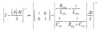
The model consists of (See Figure 1): a rectifier bridge, an input resistance (RCFL ), an input filter (LCFL or XL CFL ), a dc link capacitance (CDC ), and an equivalent resistance (REQ ) which is a function of the instantaneous dc link voltage (VDC ).
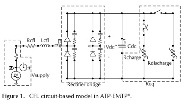
The circuit model is implemented in ATP-EMTP® allowing a comprehensive analysis of the CFL under sinusoidal and nonsinusoidal supplying voltage conditions. However, the trigger times for charge and discharges stages are previously calculated in MATLAB® through a script program. The model on these platforms enables different changes on the parameters and facilitates the study of their impact on simulation results.
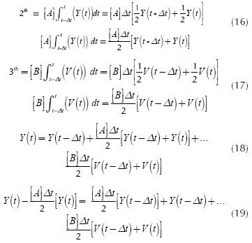
Analytical CFL model derivation
The CFL model derivation is based on the information presented in (Cresswell, 2009) and (Collin A. J., 2013). However, the CFL model script provided by (Cresswell, 2009) does not specify the solution method for the differential equation system, so that their implementation is not completely reproducible. On the other hand, (Collin A. J., 2013) proposes a generic model for a Switch Mode Power Supply (SMPS), and, unlike (Cresswell, 2009), specifies the trapezoidal integration method used to solve the differential equation system. Moreover, (Collin A. J., 2013) presents the derivation of equations for the instantaneous input current (Iin) and the instantaneous dc link voltage value (VDC) in the SMPS model. Nonetheless, some typos make it difficult to follow those derivations.
In this paper, the analytical CFL model derivation is presented including the analysis of the charging and discharging stages (See Figure 1). These expressions are then used for the implementation of the models in MATLAB® and ATP-EMTP®. The derivation starts from the KVL for each stage:
Charge Stage
Discharge stage
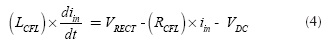
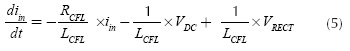
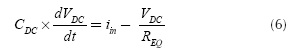
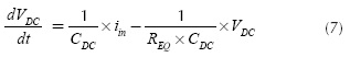
Rewriting the differential equations system (Equation (1) and Equation (2)) and neglecting (RIN LIN):
From Equation (1):
From Equation (2):
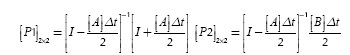
The matrix form of Equation (5) and Equation (7) is:
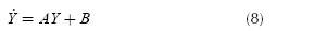
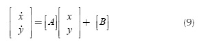
Where:
From Equation (8):
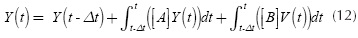
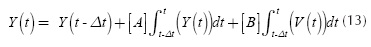
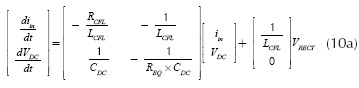
Applying trapezoidal integration method on Equation (13):
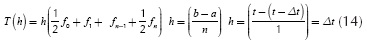
From Equation (13):

The matrix form of Equation (19):
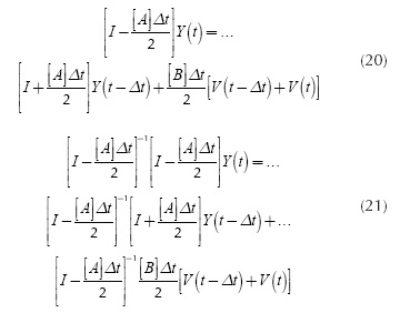
Where:
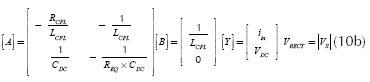
From Equation (21):
Where:
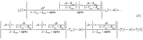
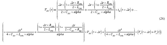
Solving the system in Equation (23):

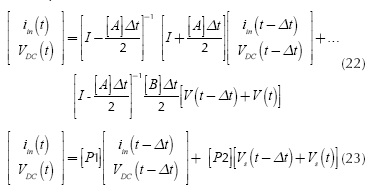
Instantaneous input current:
Instantaneous dc link voltage:
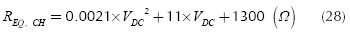
Equivalent Resistance (REQ)
The high frequency inverter and compact fluorescent tube are represented by the equivalent resistance. This equivalence results from multiple measurements of the instantaneous voltage and current at the CFL dc link in steady state.
The measurements exhibit a change when the magnitude of supply voltage varies (Collin A. J., 2013). Two regions are clearly defined and connected by two transition stages for the rectifier circuit: charge stage and discharge stage.
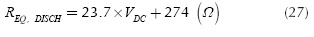
The capacitor discharge stage is the region of the upper limit and it can be described by an approximately linear function. The region of the lower limit is the capacitor CDC charging stage. However, in this it may be observed that the relationship between the equivalent resistance and VDC has a strong arc geometry.
In this way, it is possible to represent these two regions by fitting the data for two analytic functions: a linear polynomial function to the discharging stage (REQ, DISHS ) and a quadratic function for the charging stage (REQ,CH ).
For details about the fitting data to curves see (Collin A. J., 2013), where:
and (Cresswell, 2009), where:
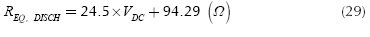
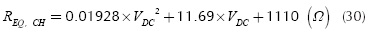
From Equation (27) to Equation (30) VDC is the instantaneous dc link voltage, REQ, DISH and REQ,CH are the equivalent resistances during discharging and charging stages of dc link capacitor, respectively.
Input Resistance (RCFL)
The input resistance provides inrush current protection and is modeled as a linear function of the CFL rated power (PCFL in W). See (Collin A. J., 2013), where:
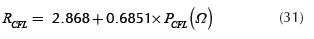
Also see (Collin, Djokic, Cresswell, Blanco, & Meyer, June 2014), where:
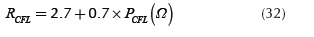
There are 230V 50 Hz CFLs on the shelf with different rated power: 5W, 8 W, 11 W, 18 W and 25 W with typical resistances corresponding to: 6Ω, 9Ω, 10Ω, 15Ω, and 20 Ω, respectively.
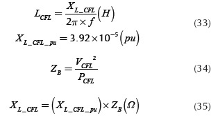
Input filter (LCFL - XL_CFL)
The inductance LCFL represents an input filter which induces an oscillation at the peak of the input current waveform. It may or may not be included in the CFL model depending on the specific components used in the ballast circuit. The inductance value is small and has little impact on low-order harmonics due to the large resistance and capacitive reactance of the conduction path. From measurements, a specific per-unit value of XL_CFL is usually adopted according to (Collin, Djokic, Cresswell, Blanco, & Meyer, June 2014). That value is used in this work.
DC link capacitance (CDC)
The CDC value is defined as a trade-off between two considerations: complying a standard harmonic distortion limit, e.g. (IEC 61000-3-2 ed4.0, 2014), and satisfying a specified tube life time. Multiple measurements show that the size of dc link capacitance is directly related to the CFL rated power. This can be compared against several manufacturers' specifications and available design data (Collin A. J., 2013).
For compact fluorescent lamps with rated power of 5 W to 25 W, typical values of CDC are between 1 µF to 5 µF (Ranging from 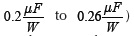 In this way, CDC is defined as a linear function of CFL rated power resulting in a relation for dc link capacitance given by the following expression (Collin A. J., 2013):
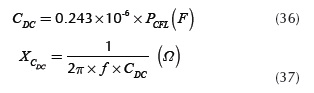
Where f is the frequency and  is the capacitive reactance.
Study Case
In this study case, the performance of the circuit-based analytical model is assessed when the sinusoidal waveform voltage source is 120V (60 Hz). The laboratory measurements for seven CFL 110/127V with different power ratings are compared with simulated MATLAB® and ATP-EMTP® circuit-based models.
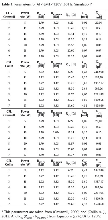
The parameters for different simulations are presented in Table 1. It can be noted that, unlike LCFL (orXLCFL ), CDC (or ) and RCFL; the equivalent resistance (REQ) is independent of the CFL power rate.
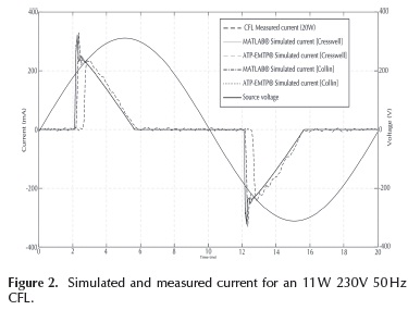
Initially, an11 W 230V 50 Hz CFL is tested using the controlled AC voltage source. This measurement is compared with the simulations of the circuit-based models. The models satisfactorily predict the current distortion; however, the circuit of the measured lamp can be slightly different than the simulated one. LCFL (XLCFL ) might be smaller or not present in the actual lamp considering the small oscillation at the peak of the measured input current waveform and the slightly difference with the current predicted by the model (See and Figure 2). Nevertheless, this requires further investigation.
Parameters for simulation 
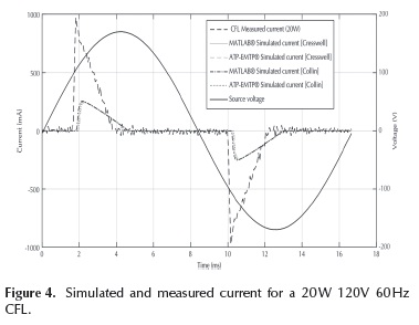
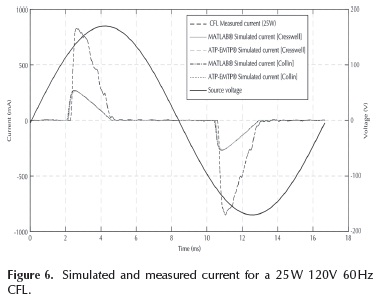
The same experiment is carried out for CFLs with different power ratings (5 W, 11 W, 15 W, 18 W, 20 W, 25 W and 27 W) supplied by a 120V 60 Hz power grid. As an example, Figure 4 and Figure 6 show the waveforms of simulated and measured current for 20 W and 25 W CFLs, respectively. It can be noted that the simulations identify charging and discharging intervals and partially predict the current waveform during charging stage. Nevertheless, the current magnitude from simulations are way smaller than the measured current in both cases. Further research is needed to correct these drawbacks.
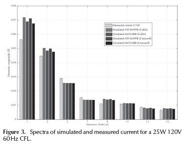
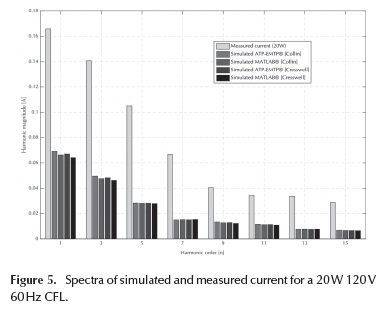
In order to compare the different results of the simulations, some indices are proposed. The Harmonic Order indices HOh for the different signals on the magnitude of the harmonic spectrum (Figure 5 and Figure 7) is evaluated.
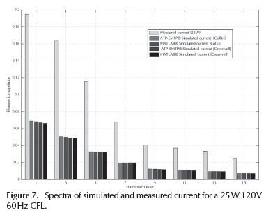
This analysis is performed on each harmonic order of current signals for different CFL power rated (Table 2), as shown in the following expression:
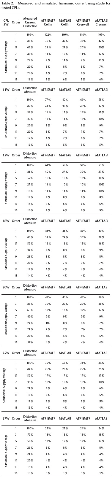
Mag1 measure: Harmonic magnitude measure for first harmonic.
Magh simulation:Harmonic magnitude simulated for each harmonic and for each implemented model.
Additionally, the Features (Max Value and Energy) are proposed and presented in Table 3. In Table 2 and Table 3, it can be observed that the larger the CFL power rating, the larger the error in the description of distortion current in the simulated models.
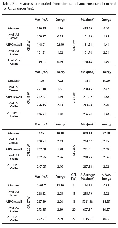
For instance, in the bottom right corner of Table 3, for the 5 W CFL, the Delta Average between Max-feature measure and Max-feature simulation result is 166.82 mA, and the Delta Average between Energy-feature measure and Energy-feature simulation result is 0.84. The same feature values for 27 W CFL are larger (1135.21 mA - 40.07).
Conclusions
This paper studies the performance in a 120V 60 Hz power grid of a novel previously proposed CFL circuit-based model (derived for 230V 50 Hz systems) via simulations and measurements of CFLs with different power ratings under sinusoidal controlled voltage supply.
The analytical derivation for the CFL model is presented in detail along with the solution for the associated differential equation system through the trapezoidal integration method. The equations for Instantaneous input current and Instantaneous dc link voltage are re-derived.
The circuit-based models are implemented in MATLAB® and ATP-EMTP®. The later easily allows changes in model parameters and simulation of the interactions with other non-lineal load models such as: current source model, equivalent Norton model and other Circuit-based models in a power distribution network.
Additionally, the results of a study case suggest that the different models do not predict the behavior of the distorted current under sinusoidal voltage supply conditions for 120V 60 Hz systems, even if they have a good performance for a 230V 50 Hz sinusoidal supply voltage.
For future research, it is important to find the circuit-based model parameters that describe correctly the CFL distorted input current under a 120V 60 Hz power supply. Likewise, the study of performance of the existing model (230V 50 Hz) under non-sinusoidal conditions and the effects of diversity and attenuation phenomena on different power quality indices should be studied via simulations and measurements in a low voltage distribution grid.
Acknowledgements
The authors wish to thank undergrad students of GISEL research group at UIS, Bucaramanga, Colombia: Thomas Medina-Perea, Cristian Martinez-Pabon, Rubén Uribe-Collante, Jose Velásquez-Maestre, who actively participated in the laboratory experiments and measurements for this work.
References
Blanco, A. M., & Parra, E. (2011). The effects on radial distribution networks caused by replacing incandescent lamps with compact fluorescent lamps and LEDs. Ingeniería e Investigación, 31(2), 97-101. [ Links ]
Blanco, A., Stiegler, R., & Meyer, J. (2013). Power quality disturbances caused by modern lighting equipment (CFL and LED). IEEE PowerTech (POWERTECH),. Grenoble. [ Links ]
Cagni, A., Carpaneto, E., Chicco, G., & Napoli, R. (2004). Characterisation of the aggregated load patterns for extraurban residential customer groups. Electrotechnical Conference MELECON 2004. Proceedings of the 12th IEEE Mediterrane. DOI: 10.1109/melcon.2004.1348210. [ Links ]
Collin, A. J. (2013). Advanced load modelling for power system studies. Edinburgh UK: Univ. Edinburg. Obtenido de https://www.era.lib.ed.ac.uk/handle/1842/8890. [ Links ]
Collin, A., Djokic, S., Cresswell, C., Blanco, A., & Meyer, J. (June 2014). Cancellation of harmonics between groups of modern compact fluorescent lamps. Power Electronics, Electrical Drives, Automation and Motion (SPEEDAM), 2014 International Symposium on. Ischia. [ Links ]
Cresswell, C. E. (2009). Steady-st ate load models for power syst em st udies. Edinburgh: Univ. Edinburgh. Obtenido de https://www.era.lib.ed.ac.uk/handle/1842/3846. [ Links ]
Djokic, S., & Collin, A. (2014). Cancellation and attenuation of harmonics in low voltage networks. Harmonics and Quality of Power (ICHQP), 2014 IEEE 16th International Conference on. Bucharest DOI: 10.1109/ichqp.2014.6842856. [ Links ]
IEC 61000-3-2 ed4.0. (2014). Electromagnetic compatibility (EMC) - Part 3-2: Limits - Limits for harmonic current emissions (equipment input current < 16 A per phase). Ginebra: International Electrotechnical Commission. [ Links ]
Lamedica, R., Prudenzi, A., Tironi, E., & Zaninelli, D. (1997). A model of large load areas for harmonic studies in distribution networks. IEEE Transactions on Power Delivery, 12(1), 418--425 DOI: 10.1109/61.568266. [ Links ]
Malagon-Carvajal, G., Ordonez-Plata, G., Giraldo-Picon, W., & Chacon-Velasco, J. (2014). Investigation of phase shifting transformers in distribution systems for harmonics mitigation. Power Systems Conference (PSC), 2014 Clemson University. Clemson S.C. DOI: 10.1109/PSC.2014.6808119. [ Links ]
Mansoor, A., Grady, W., Chowdhury, A., & Samotyi, M. (1995). An investigation of harmonics attenuation and diversity among distributed single-phase power electronic loads. IEEE Transactions on Power Delivery, 10(1), 467-473. DOI: 10.1109/61.368365. [ Links ]
Mansoor, A., Grady, W., Staats, P. T., Thallam, R., Doyle, M., & Samotyj, M. (1995). Predicting the net harmonic currents produced by large numbers of distributed single-phase computer loads. IEEE Transactions on Power Delivery, 10(4), 2001-2006. DOI: 10.1109/61.473351. [ Links ]
Matvoz, D., & Maks, M. (2008). Impact of compact fluorescent lamps on the electric power network. International Conference on Harmonics and Quality of Power. Wollongong, NSW DOI: 10.1109/ichqp.2008.4668864. [ Links ]
Nassif, A., & Acharya, J. (2008). An investigation on the harmonic attenuation effect of modern compact fluorescent lamps. Harmonics and Quality of Power, 2008. ICHQP 2008. 13th International Conference on. Wollongong, NSW. DOI: 10.1109/ICHQP.2008.4668759. [ Links ]
Rawa, M., Thomas, D., & Sumner, M. (2012). Harmonics attenuation of nonlinear loads due to linear loads. Electromagnetic Compatibility (APEMC), 2012 Asia-Pacific Symposium on. Singapore. DOI: 10.1109/APEMC.2012.6237838. [ Links ]
Ribeiro, P., Leitao, J., Lira, M., Macedo, J., Grandi, A., Testa, A., ... Browne, N. (2011). Harmonic distortion during the 2010 fifa world cup. Power and Energy Society General Meeting. San Diego, CA. DOI: 10.1109/PES.201 1.6039369. [ Links ]
Romero, A. A., Zini, H. C., & Ratta, G. (2011). An overview of approaches for modelling uncertainty in harmonic load-flow. Ingeniería e Investigación, 31 (2), 18-26. [ Links ]
Sajjad, I., Chicco, G., & Napoli, R. (2014). A statistical analysis of sampling time and load variations for residential load aggregations. Multi-Conference on Systems, Signals Devices (SSD), 2014 11th International. DOI: 10.1109/SSD.2014.6808851. [ Links ]
Salles, D., Jiang, C., Xu, W., Freitas, W., & Mazin, H. (Oct. 2012). Assessing the Collective Harmonic Impact of Modern Residential Loads-Part I: Methodology. IEEE Transactions on Power Delivery, 27(4), 1937-1946. DOI: 10.1109/TPWRD.2012.2207132. [ Links ]
Task Force on Harmonics Modeling and Simulation. (1996). Modeling and simulation of the propagation of harmonics in electric power networks. I. Concepts, models, and simulation techn. Power Delivery, IEEE Transactions on, 11 (1), 452-465. [ Links ]
