


Serviços Personalizados
Journal
Artigo
 Inglês (pdf)
 Artigo em XML
 Referências do artigo
 Enviar este artigo por email
Indicadores
-
 Citado por SciELO
 -
 Acessos
Links relacionados
-
 Citado por Google
 -
 Similares em
SciELO
Similares em
SciELO -
 Similares em Google
Compartilhar

 Permalink
Ingeniería e Investigación
versão impressa ISSN 0120-5609
Ing. Investig. vol.36 no.1 Bogotá jan./jun. 2016
https://doi.org/10.15446/ing.investig.v36n1.46221
DOI: http://dx.doi.org/10.15446/ing.investig.v36n1.46221
The installation of a common rail diesel engine on a light helicopter of the eurocopter EC120 class
Instalación de un motor diesel common rail en un helicóptero ligero de la clase eurocopter EC120
L. Piancastelli1, and L. Frizziero2
1 Luca Piancastelli. PhD in Mechanical Engineering. Affiliation: Full Professor at Department of Industrial Engineering, alma mater studiorum Università di Bologna, Italy.
Email: luca.piancastelli@unibo.it.
2 Leonardo Frizziero: PhD in Mechanical engineering. Affiliation: Assistant Professor at Department of Industrial Engineering, alma mater studiorum Università di Bologna, Italy.
Email: leonardo.frizziero@unibo.it.
How to cite: Piancastelli, L., & Frizziero, L. (2016). The installation of a common rail diesel engine on a light helicopter of the eurocopter EC120 class. Ingeniería e Investigación, 36(1), 06-13. DOI: http://dx.doi.org/10.15446/ing.investig.v36n1.46221.
ABSTRACT
A feasibility study for the installation of a CRDID (Common Rail Direct Injection Diesel) on a light helicopter is introduced. The total mass available for the CRDID is evaluated starting from fuel consumption and helicopter data. The conversion of an automotive unit was discarded to excessive mass and excessive costs of the conversion. A derivative of an automotive engine was then considered. This solution proved to be feasible. The installation of the new CRDID was then studied. The turbocharger and the cooling system were defined for the application. The result was the evaluation of the power plant installation mass that proved to be much lower than the maximum admissible. The installation is then possible.
Keywords: Helicopter, diesel, common rail.
RESUMEN
Se presenta un estudio de factibilidad para la instalación de un CRDID ( Common Rail Direct Injection Diesel por sus siglas en ingles) en un helicóptero ligero. La masa total disponible para el CRDID se calcula a partir de los datos de consumo de combustible y datos de helicópteros. La conversión de una unidad de automoción se descartó debido a los costos excesivos en masa, y costos excesivos en conversión. A continuación se considera un derivado de un motor de automóvil. Esta solución ha demostrado ser factible. Posteriormente, se estudió la instalación de la nueva CRDID. El sistema de refrigeración y el turbocompresor se definieron para la aplicación. El resultado fue el calculo de la masa de instalación de la planta de energía que resultó ser mucho menor que el máximo admisible. La instalación es entonces realizable.
Palabras clave: Helicóptero, diésel, conducto común.
Received: October 15th 2014 Accepted: February 3rd 2016
Introduction
At first glance, the turboshaft engine provides more power to the helicopter with a lower weight penalty than CRDIDs, with their "heavy engine blocks" and auxiliary components. The improvements in turboshaft engines in the late 20th century have been a critical factor behind helicopter higherperformance development. Turboshaft engines were the only choice for the preferred helicopter power plants. However, higher engine and fuel prices with the low fuel efficiency of small turbines have reintroduced the option of powering light single-engine helicopters with advanced reciprocating engines instead of conventional small turboshaft engines in order to contain costs, to reduce pollutant emissions and fuel consumption. Soaring oil prices, high operating costs and growing public concern for environment protection have also become essential factors in future choices.
This paper provides an answer to the question of which is the optimal diesel engine for a light helicopter, starting from its expected performances. In order to meet this objective, a multi-criteria analysis was undertaken to cover the issues of mechanical and thermal loads and interactions with the helicopter body.
A primary advantage of CRDIDs is the possibility to use non-explosive automotive diesel fuel. In fact, diesel not only reduces the fire hazards, but also simplifies the supply and storage chain both for civilian and military use. While jet fuel is available mainly in airport, automotive diesel is the most common fuel in the world. A standard private helicopter owner with his own landing site has often to sustain the huge expensive of refueling at the nearest local airport. This fact is an important limitation in private helicopter diffusion, especially for light, general aviation helicopters. The use of a CRDID with FADEC poses a signiicant challenge to the designer, who should reduce fuel consumption, noise levels, emissions, purchase and maintenance costs. Both diesel and Jet fuel have to be used.
In this paper it was also investigated whether conversions from the car-manufacturing industry can be applied to light helicopters. This paper is articulated in the following pars: optimal CRDID choice, engine/rotorcraft integration and environmental impact analysis.
The EC120 platform
The EC120 helicopter is a typical light helicopter for general aviation, its main data are summarized in Table 1:
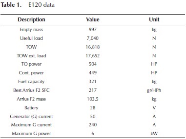
It should be noted that, starting from author data, the CRDID lowers SFC and the excellent off-design performance makes it possible to reduce fuel consumption of 60 to 75 %. It is then possible to reduce the fuel load. For the CRDID powerplant, consider Equation (1):

This "available mass" is conservative, since the main rotor disk loading is reduced and so the net thrust is increased. The internal tank can also be reduced in volume and in mass. Another factor to be considered is that the CRDID is not sensitive to high OAT (Outside Air Temperatures) up to ISA + 20°C, with a reduction of 1 % for ISA + 35°C. The maximum power is usually kept up to 6000m, depending on the turbocharger choice.
Since the TO weight is reduced, the maximum power required to the CRDID can be re-calculated in a conservative way, as shown in Equation (2):
Available CRDIDs from the automotive market
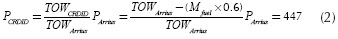
A few CRDIDs from the automotive market are known to the authors. Their performances are summarized in Table 2.
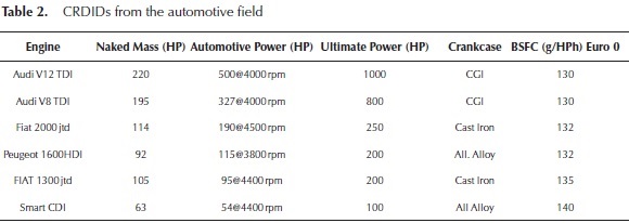
The term "naked" stands for an engine without coolant, lubricants and alternator. The automotive engines are also stripped of all the components that are not necessary for the aircraft application (Euro 0). A few comments are needed on the ultimate power concept. Automotive engines have the problem of torque at low rpm. It is torque that moves the wheels through the transmission. A common optimization point for CRDIDs in the European market is the motorway optimum speed point. This means low rpm, highest gear and standard velocity; for instance, 1750 rpm, 6th speed and 120 km/h. This condition is particularly unfavorable for the CRDID, since the crankshaft speed is very low, and this means relatively low oil pressure and problems of pistons and journal bearing cooling. For the journal bearing, the peripheral velocity can be low and insuficient minimum oil thickness may take place. The peak pressure in the combustion chamber is in the indicator cycle, near the TDC, usually in the range from 0 to + 18° After TDC (ATDC). Its position depends nearly on its peak, since torque is already very high and efficiency should be the best possible. Inertia loads are very low and they subtract a little amount of inertia loads induced by piston and rod at the TDC (Top Dead Center). The fuel also plays a very important role in this position and compensation maps of the FADEC cannot be perfect. The automotive engine is then optimized for this situation that is also included in the standard cycle for the EURO xxx emission tests. This highly stressed design point is not included in the aerial vehicle envelope. This condition never happens to the helicopter or even to a common aerial vehicle, where the propeller driven load follows a cubic law. In the automotive ield, the TC/ETC (Turbo Charger/Electric Turbo Charger) follows the piston engine with turbolag. Low inertia, low friction, straight ducts (especially on the exhaust) are fundamental to obtain good performances. The optimization is aimed to best eficiency during transient. This result is obtained through optimum compactness of the TC, the installation and the aftercooler. Minimum sizing or undersizing is fundamental. Short ducts and small volumes are used to have immediate throttle response, more room and lower costs. From the automotive market, only the heat exchangers are really useful for the aerial vehicle ield, since they are very small, efficient and reliable. Piping, fittings, TCs... are usually too small or of insufficient quality to be used in a world where a failure means a forced landing. The other important aspect is the rpm and load range. In the case of aerial vehicles, the used range is from 50 % to 100 %. The aerial vehicle uses full output power at every take off; the car, in many cases, never needs it. In a few model of sport car, the ECU (Electronic Control Unit) had a memory to record the load history. For a few car models, produced in thousands of items, the maximum power was never reached by any car or any user. Torque at low rpm is not needed. In Figure 1 it is possible to see the Automotive Torque and the Aircraft Torque for the same engine.
The torque and the crankcase speed are normalized with the maximum automotive values. As it can be seen, the automotive engine has high torque at low rpm. The airengine has a larger turbo. This turbo is not working at low rpm and starts to work properly at 50 % of the maximum rpm. From this point on, the power output is acceptable. Near the maximum rpm, the injection starts to cut in order to arrive to the desired value of maximum power. An increase of 20 % in maximum rpm is not unusual. In fact, the crankshaft should never fail in cars. To obtain the required reliability level, a 15 % increase in rpm from the maximum design requirement is usual. The air engine is checked thoroughly and the balancing is done to the best possible. Pistons and rod are reworked and polished to achieve better performance. Rods may be replaced or treated to improve fatigue life. For all of these reasons, the aircraft engine has an "ultimate" maximum power higher than the automotive one. Intake and exhaust manifold are usually replaced and all the parts that are not strictly necessary are removed. The engine "naked" of Table 1 is the engine without accessories and turbocharger. The BSFCs (Brake Speciic Fuel Consumption) are similar, with the exception of the one derived from the Smart CDI, that has, in this case, the maximum relative increment of output power. This is paid by a small penalty in SFC (Speciic Fuel Consumption). Just as a irst approximation the output power of an aircraft, conversion can be evaluated with Equation (3):
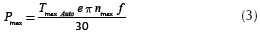
where T max Auto is the maximum torque of the automotive engine, and e is a factor that takes into account that the conversion from Euro 5 to Euro 0 makes it possible to eliminate several pressure drops in the air-exhaust system of the engine. In particular, the debimeter, the intake butterfly valve, the catalysts and the particulate filter can be removed. e can be around 1.15 (15 % increase in torque) in many engines. f is the factor that takes into account the possible increment in the maximum crankshaft speed. A reasonable value may be around 1.15 (15 %). Table 3 summarizes the values calculated with Equation (3) and the ultimate values. Just to be clear, this ultimate power values have to be reduced to take into account several factors, among which the fuel is the most important, with cetane number and density variations.
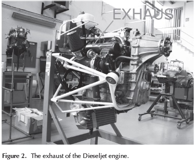
So, even with this extremely simplified formula, the results are acceptable, with the exception of the FIAT 2000 jtd. It should be noted that tests are to be carried out and "weak" components should be detected. It is a good rule not to remove a working engine from the brake just to send it to the wrecking yard. Failure in CRDIDs may be tricky; in fact, thermal fatigue may reveal the damage at the successive start up. Since turbolag is not important, it is convenient to vary the geometry of intake and exhaust. In Figure 2, it is possible to see the exhaust of the TDA CR1.9 8V from Dieseljet. This engine is a conversion of the FIAT 1,900 jtd 8V automotive engine. In the design of turbocharged CRDIDs, the selection of the most effective exhaust configuration of the turbocharging system is very important. Engine performances are in fact affected by the gas flow unsteadiness. Four different systems are generally adopted: the constant pressure turbocharging system, the pulse turbocharging system, the pulse converter turbocharging system and the modular pulse converter turbocharging system. In the constant pressure turbocharging system, the exhaust gases coming from all cylinders flow into a common exhaust reservoir, whose volume is sufficiently large to damp down the unsteady flow, and then feed one single-entry turbine. In this case, if it is possible, the exhaust ducts should be divergent to reduce velocity and recover pressure.
A maxim angle of 7° is advised and a trumpet shape is better. In this case, the fluctuating gas flow from the cylinders is damped so that the conditions at the turbine entry are the most steady possible with time, providing a nearly constant pressure turbocharging. Since the mass flow is relatively constant, high eficiency of the turbine and the compressor is achieved. This is the most advantageous situation for aerial vehicle application. At the same time, it is the reason why it is not used in automotive application. The disadvantage of this kind of turbocharging system is turbolag. The frictional losses, due to the mixing process between exhaust flows, coming from different cylinders, damp the kinetic energy. The transient responses of this kind of turbocharging system are then poor.
For the automotive ield a better utilization of the exhaust kinetic energy can be obtained by adopting the pulse turbocharging system, in which the available energy at the turbine is greater than the constant pressure turbocharging system architecture. However, the turbine efficiency is lower because the gas flow into the turbine is highly unsteady and the turbine operates under extremely variable conditions. The flow unsteadiness in the pulse turbocharging system can be reduced by grouping together several cylinders in a common exhaust pipe, which is then connected to a pulse converter. This kind of turbocharging is called the pulse converter turbocharging system. This system can be also used in aerial vehicle application. The disadvantages of this kind of turbocharging system are that the exhaust is complicated and heavy. In a mass produced automotive exhaust it is possible to ind a simpliied version of pulse exhausts. In fact, in Euro 4 - 6 CRDIDs the presence of a catalyst after the turbine greatly reduces the advantages of this solution. In our helicopter application, the irst engine that reaches the required power level is the AUDI V8 engine. However, just as a first approximation, it is necessary to evaluate the installed mass of this engine, In our case, with everything, except lubricant and cooling, a reasonable mass is 210 kg. For the installation mass it is possible to use known data from other engines. For instance, for the Rotax 912 engine the dry mass is 75kg, while the installed mass is 95kg. Hence, the AudiV8 mass can be calculated as MAUDIV8 = 210*95/75 = 266 kg. This mass is below MCRDID and this engine can be installed. The Audi V8 runs at 4,000 rpm, while the Arrius has a shaft speed of 6,000 rpm. For this reason, a speed reducer should be used; a clutch should also be installed to start the engine with the main rotor still. The lightest way to do so is to use a carbon disk racing clutch with integrated spring decoupling joint, a CFRP clutch casing and a timing belt speed multiplier with reinforced PEEK wheels.
The available mass for this operation is MCRDID-MAUDIV8 = 296 - 266 = 30 kg. Unfortunately, the generator and the cooling fan masses should also be added, so that the installation is quite at mass limit. Another problem is the rpm settings which should be at the maximum possible (5,200 rpm). At this crankshaft speed, the automotive engine should be upgraded by the substitution of several components, such as, for example, the connecting rods. The problem is that on the helicopter the engine is always at maximum speed, so in order to guarantee an acceptable TBO, several components have to be upgraded. For instance, the cylinder liners should be surface-treated and the piston rings should be substituted. The same should be made on the camshafts side, which should be fully surface treated, with improved springs, rocker arms...etc. Luckily, the racing-derived journal bearings are favored by the high speeds and, with a proper lubricant type and the improved technology, can easily bear the load.
However, all these operation will increase the cost of the engine for a factor that may easily equal to ive times as much as the cost of the original automotive unit. The inal result may be doubtful at least on the installation mass. It is probable that a payload reduction will be required. Development cost will include long times at the brake to verify the reliability of the assembly. Another feasible solution is to install two Fiat 2000 jtd engines. In this case the mass will be even larger. Thereby, at least with this limited choice of engines, an automotive-converted CRDID does not seem to be convenient. Nonetheless, automotive lighter and more performing CRDIDs are introduced every day on the market; it is probable that in the near future, or, due to lack of knowledge of the authors, at present this conversion is or will be possible.
Automotive derived CRDIDs
The critical part of a CRDID is the combustion chamber and the intake ducts inside the head. It is common practice to use the same cylinder heads, pistons, ducts, injectors, maps...for a family of engines. Slight modification in stroke can be introduced without affecting too much the combustion process. This is a simpliication, since manifolds, engine architecture, etc., are also important. However, in order to save development time and costs, modularity is fundamental. The engines are developed by families. In our case it is possible to derive the "new" engine from an existing one. For example, it is perfectly possible to derive the new engine from the Smart cdi with a V16 (flat 16) and about 400 HP maximum output power, or a V12 (flat 12) from the 1300jt.
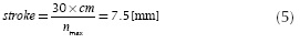
These engines would have the advantage to have many combustions per cycle with low torque oscillations and minor problems of overload on the main rotor speed reducer, that is conceived for the very smooth torque oscillations of the power turbine. The 12 and 16 cylinders engines are very balanced and very easy to start. Given the fact that the unitary displacement is very small, these are very fast CRDIDs. The 1300 jtd derived unit would not even need a speed reducer. This would be the ideal choice. However, a new head should be manufactured. This means a new casting for two six cylinder rows (one casting for the two is possible) and a whole new series of tests for head strength and durability. For this reason, it is better to use the less balanced and smooth V8 derived from the 2000 jtd heads. This solution has also the advantage that it is possible to machine work the original castings in order to derive the new heads. The FIAT 2000 jtd heads are very sturdy castings, that with a little work on minor components and on the intake ducts can easily reach 250 HP at nmax = 4,500 rpm. All the other CRDID parts can be machine cut from stock without the necessity of castings, at least for the prototypes. This solution has several additional advantages, including the possibility to install the new power unit directly onto the ARRIUS installation hard points on the helicopter frame. Shock absorbers will be necessary in any case. Since low rpm power is not important, the stroke can be slightly reduced in order to lower average piston speed and the compression ratio. The mean piston speed of the original engine is:
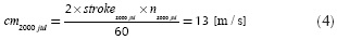
It is then possible to reduce the cm to a better 10 [m/s] that is typical of long endurance diesel engines for trains and trucks; hence, the new stroke will then be (5):
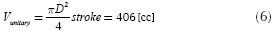
The new engine will have a unitary displacement of (6) and a total displacement of 3250 cc.
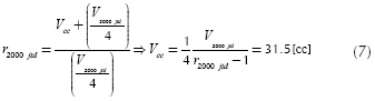
This will change the engine compression ratio. The combustion chamber volume of the 2000 jtd can be calculated with (7):
The compression ratio of the new engine can then be calculated by (8):
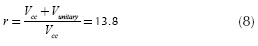
Since the new compression ratio is larger than the limit value 12.5, the new engine will easily start. The reduction of the stroke makes it possible to reduce the engine overall dimensions and will signiicantly reduce the overall weight. A preliminary CAD design of the engine can be performed in order to obtain a reasonable overall weight of the powerplant. Before the process can be started, some choices should be made. The irst is the angle between the rows of the V8. From the vibration point of view and for the stress and weight of the crankshaft, a fully balanced V8-90° is to be preferred.
he single turbocharger coniguration is lighter and also has the advantage of increasing the maximum pressure ratio available. As a rule of the thumb, the larger the turbocharger is, the higher the pressure ratio will also be. The classical configuration of Forghieri's Ferrari F1 1981 will be adopted (Figure 3). This coniguration has several advantages. The irst one is that the engine is mounted on the top of the frame. Installing the extremely hot turbocharger(s) below the engine will increase helicopter frame temperature. Even if a titanium alloy shield is present, this will only partially solve the problem.
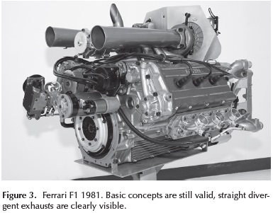
The turbochargers will have to be insulated, with complications and mass increase. In the case of top mounted turbochargers, it is possible to adopt a high temperature CFRP fairing (Carbon Fiber Reinforced Plastic) that can withstand up to 1100°C. This top fairing can be locked in such a way in order to avoid that the inexperienced user in a routine check opens it. Another concern is safety. The turbochargers may take ire in extreme conditions; in this case, having the turbochargers on the top of the engine will give more time to land. Last but not least, it is possible to choose the best exhaust. A very short convergent one for additional thrust, a longer trumpet one for pressure recovery and best eficiency, or a straight one can be used. Additionally, the direction of the exhaust is also relevant; the complex flux of the exhaust can be optimized. In this case, the optimization can be performed both by CFD (Computational Fluid Dynamic) simulation and flying tests.
In Figure 3, it can be seen that the best F1 turbocharged engine of the 1981 season had all the basic concepts: straight divergent exhausts; the small and straight exhaust ducts from heads to the enormous turbochargers available at that time. Notice the "monster" wastegate on the left hand side and the "primitive" electronic actuator. The pop-off valves on the intake are also visible.
As it can be seen in Figure 4, the new CRDID is extremely simple. The wet sump is partially reflected on the floor to show the shock absorber mounts. This arrangement will allow to keep the original helicopter installation. A geared speed multiplier was used instead of the belt due to more compactness. The wet sump is inclined toward the speed multiplier. A geared oil sump is to be used; while for the water cooling electrical redundant pumps will be used. The light alloy double HPP (High Pressure Pump) and the camshafts are moved by a single carbon iber reinforced timing belt. These belts are oil resistant and last for engine life. For simplicity reasons, the 8V heads were mounted in place of the new 16V. This due to the fact that they are interchangeable and a CAD model of the 16V head was not available. A carbon clutch with integrated spring decoupler on the high speed shaft will be used. The FADEC (Full Authority Digital Electronic Control) will control the engagement after the engine is started. In order to simplify the machining from the stock, the crankcase and the cylinders are machined separately. The studs will connect the three parts to the heads. This solution makes it possible to make the crankcase with high strength titanium alloy and the cylinders with aluminum alloy with steel liners. This is an extremely lightweight solution. Racing derived journal bearings and a machine cut AISI 300m steel alloy will complete the assembly. An inconel, welded, F1 style, constant pressure exhaust is used. The turbocharger is top mounted and bolted directly to the exhaust "spider". This makes it possible for the exhaust to expand freely from ambient temperature to 950°C.
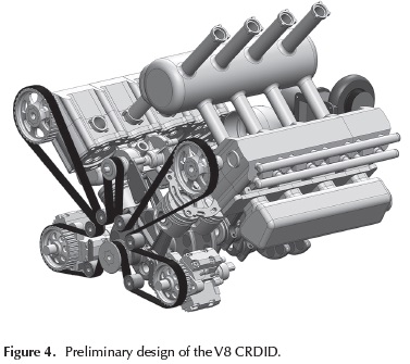
The clutch and the use of diesel fuel will make it possible to refuel the helicopter with the engine running. A starter/ generator installed on the flywheel will start the engine. The 6 kW original generator should be replaced with a water cooled brushless unit. For reliability, it is better to use two 3 kW generators in parallel instead of a single one. The engine will not run for long time without the generator. CR injectors, especially the solenoid ones, have significant energy consumption.
Turbocharger selection
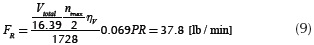
For the preliminary design, a turbocharger from the Garrett catalogue will be selected. The flow rate (FR) formula (9) gives:
Ambient Air Temperature AAT at ISA-50°C (International Standard Atmosphere with an offset of -50°C) is -31F. The Atmospheric Pressure AP is 14.69 psi. From this data, we calculate the Corrected Flow Rate CFR at 0m, by:
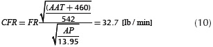
From the helicopter flight manual it is possible to take off at full load up to 12000 ft. So the other boundary condition is ISA + 20°C@12000 ft. At this altitude, the pressure is pa = 0.63 bar. In order to have 3 bar into the manifold (CRDID full power) it is necessary to increase the pressure ratio to PRmax (11):

With a new FR = 59 [lb/min] and a CFR = 47 [lb/min], the Garrett 6TX3076R seems to satisfy the requirements.
Cooling system
Our CRDID needs of 3 separate cooling systems for air, liquid and lubricant. The aftercooler should cool the air down to a maximum of 70°C (best 50°C). In order to save weight, an air to air solution should be chosen. Liquid to air radiators are necessary, while for the lubricant it is possible to choose air-to-lubricant or coolant to lubricant. This latter is more common due an easy installation. The first to choose is the air intake, which is most critical for helicopter in hovering at take off. The original helicopter has the air intake visible in Figure 5:
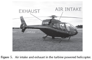
This air intake has been approved by the manufacturer of the turboshaft for his engine. For this reason it is better to use a modified version of the original air intake. Since the overall efficiency of the turboshaft is lower than the one of the CRDID, the amount of air should be sufficient, even during the critical hovering condition. Hemce, a duct should be designed from this air intake to the radiator pack of the CRDID that will be composed of an aftercooler (frontal) and a liquid radiator behind the aftercooler. Two electric fans will provide the necessary air flow (Figure 6):
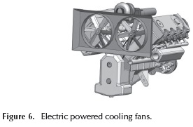
The coolant water temperature will be regulated by the electric pump on the liquid and by the electric fan on the air; the FADEC will easily control the system from sensors installed in suitable points. The exhaust can work as an ejector to improve cooling if necessary (Figure 7).
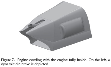
The engine air intake should be separated from the cooling circuit; in Figure 7 a dynamic air intake is depicted. Air intake position should be designed in a positive pressure area of the helicopter to improve the pressure ratio and the overall eficiency of the system. If possible, an NACA air intake can be used to reduce drag and to increase lift.
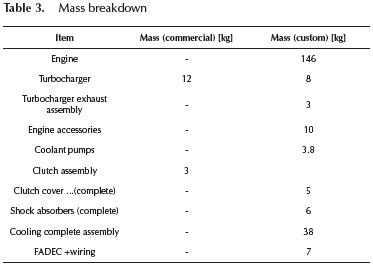
Mass breakdown
The mass breakdown is summarized in Table 3. It is composed by two different columns, one from the commercial components, and the other from custom components.
As it can be seen, the whole mass is 228kg with special turbocharger unit and 4 kg more (232) with the standard commercial turbocharger. This mass is lower than the maximum 297 kg. Thereby, the installation can be fully studied and designed.
Conclusions
The installation of a conversion of an automotive engine proved to be unfeasible. The automotive engine required extensive reworking, with expensive surface treatment and part substitution. The engine was very different from the automotive unit and should have required extensive tests both on brake and on helicopter. The automotive conversion would have an excessive mass, requiring a reduction of helicopter TOW. An automotive derived engine was then considered. The heads, the pistons and the common rail assembly were taken from a commercial FIAT 2000 Multijet engine.A V8 was derived from the application and a preliminary design of the new unit was carried out. The mass of the new design was estimated. Then, the installation of this new design was considered. The new CRDID assembly proved to be well below the maximum allowed to preserve the performances of the original turbine-powered helicopter. The advantages of the CRDID conversion will be: a nearly halved fuel consumption and the possibility of using diesel fuel with reduced fire hazards and easy supply. It is also possible to have the equivalent of Euro 6 automotive standard by adding a SCR system.
In general, it is probably a good time to propose the use of diesel fuel, but we think that Diesel technology can be always a good way to be run in aeronautical field; in fact it has many advantages regarding reliability and safety: automotive quality and no risks of firing.
References
J. Rushby, "Formal Methods and the Certification of Critical", 1993. [ Links ]
R. Rogers, Capt. "Flight test results of the controlled flight into terrain avoidance maneuvre in fly-by-wire transports". ALPA, March 1999. [ Links ]
P.B. Ladkin. (1998). Computer-Related Incidents with Commercial Aircraft. A Compendium of Resources, Reports, Research, Discussion and Commentary, http://www.rvs.uni-bielefeld.de/publications/Incidents/. [ Links ]
NASA. "F-8 Digital Fly-By-Wire". California: 1994. [ Links ]
Brubaker D.I., Sheerer C. (1992). Fuzzy-logic system solves control problem, EDN, Design Feature, pp. 121-127. [ Links ]
Stowe, S. (2000). Fly-By-Wire: A Primer for Aviation Accident Investigators, ALPA, February. [ Links ]
Dornheim, M.A. (1991). X-31 flight tests to explore combat agility to 70 deg. AOA, Aviation Week and Space Technology, pages 38-41, March 11. [ Links ]
L. Piancastelli, L. Frizziero, G. Zanuccoli, N.E. Daidzic, I. Rocchi.( 2013). A comparison between CFRP and 2195-FSW for aircraft structural designs, International Journal of Heat and Technology, Volume 31, Issue 1, Pages 17-24. [ Links ]
L. Piancastelli, L. Frizziero, N.E. Daidzic, I. Rocchi. (2013). Analysis of automotive diesel conversions with KERS for future aerospace applications, International Journal of Heat and Technology, Volume 31, Issue 1, pages 143-154. [ Links ]
L. Piancastelli, L. Frizziero, I. Rocchi. (2012). An innovative method to speed up the finite element analysis of critical engine components, International Journal of Heat and Technology, vol. 30, Issue 2, pp. 127-132. DOI: 10.18280/ijht.300218. [ Links ]
L. Piancastelli, L. Frizziero, I. Rocchi. (2012). Feasible optimum design of a turbocompound Diesel Brayton cycle for diesel-turbo-fan aircraft propulsion, International Journal of Heat and Technology, Volume 30, Issue 2, Pages 121-126. DOI: 10.18280/ijht.300217. [ Links ]
L. Piancastelli, L. Frizziero, E. Morganti, A. Canaparo. (2012). The Electronic Stability Program controlled by a Fuzzy Algorithm tuned for tyre burst issues, Published by Pushpa Publishing House, Far East Journal of Electronics and Communications, ISSN: 0973-7006, Volume 9, Number 1, pages 49-68, Allahabad, India. [ Links ]
L. Piancastelli, L. Frizziero, I. Rocchi, G. Zanuccoli, N.E. Dai-dzic. (2013). The "C-triplex" approach to design of CFRP transport-category airplane structures, International Journal of Heat and Technology, ISSN 0392-8764, Volume 31, Issue 2, Pages 51-59. [ Links ]
L. Frizziero, I. Rocchi. (2013). New inite element analysis approach, Published by Pushpa Publishing House, Far East Journal of Electronics and Communications, ISSN: 09737006, Volume 11, Issue 2, pages 85-100, Allahabad, India. [ Links ]
L. Piancastelli, L. Frizziero, E. Pezzuti. (2014). Aircraft diesel engines controlled by fuzzy logic, Asian Research Publishing Network (ARPN), Journal of Engineering and Applied Sciences, ISSN 1819-6608, Volume 9, Issue 1, pp. 30-34, EBSCO Publishing, 10 Estes Street, P.O. Box 682, Ipswich, MA 01938, USA. [ Links ]
L. Piancastelli, L. Frizziero, E. Pezzuti. (2014). Kers applications to aerospace diesel propulsion, Asian Research Publishing Network (ARPN), Journal of Engineering and Applied Sciences, ISSN 1819-6608, Volume 9, Issue 5, pp. 807-818, EBSCO Publishing, 10 Estes Street, P.O. Box 682, Ipswich, MA 01938, USA. [ Links ]
L. Piancastelli, L. Frizziero, G. Donnici. (2014). A highly constrained geometric problem: The inside-outhuman-based approach for the automotive vehicles design, Asian Research Publishing Network (ARPN), Journal of Engineering and Applied Sciences, ISSN 1819-6608, Volume 9, Issue 6, pp. 901-906, EBSCO Publishing, 10 Estes Street, P.O. Box 682, Ipswich, MA 01938, USA. [ Links ]
L. Frizziero, F. R. Curbastro. (2014). Innovative methodologies in mechanical design: QFD vs TRIZ to develop an innovative pressure control system, Asian Research Publishing Network (ARPN), Journal of Engineering and Applied Sciences, ISSN 1819-6608, Volume 9, Issue 6, pp. 966-970, EBSCO Publishing, 10 Estes Street, P.O. Box 682, Ipswich, MA 01938, USA. [ Links ]
L. Piancastelli, L. Frizziero.( 2014). How to adopt innovative design in a sportscar factory, Asian Research Publishing Network (ARPN), Journal of Engineering and Applied Sciences, ISSN 1819-6608, Volume 9, Issue 6, pp. 859-870, EBSCO Publishing, 10 Estes Street, P.O. Box 682, Ipswich, MA 01938, USA. [ Links ]
L. Piancastelli, L. Frizziero, I. Rocchi. (2014). A low-cost, mass-producible, wheeled wind turbine for easy production of renewableenergy, Published by Pushpa Publishing House, Far East Journal of Electronics and Communications, ISSN: 0973-7006, Volume 12, Issue 1, pages 19-37, Allahabad, India. [ Links ]
L. Piancastelli, L. Frizziero, E. Morganti, A. Canaparo. (2012). Fuzzy control system for aircraft diesel engines edizioni ETS, International journal of heat & technology, ISSN 03928764, Vol. 30, N.1, pages 131-135. [ Links ]
L. Piancastelli, L. Frizziero, T. Bombardi. (2014). Bezier based shape parameterization in high speed mandrel design, International Journal of Heat and Technology, vol. 32, Issue 1-2, pp. 57-63. [ Links ]

