


Serviços Personalizados
Journal
Artigo
 Inglês (pdf)
 Artigo em XML
 Referências do artigo
 Enviar este artigo por email
Indicadores
-
 Citado por SciELO
 -
 Acessos
Links relacionados
-
 Citado por Google
 -
 Similares em
SciELO
Similares em
SciELO -
 Similares em Google
Compartilhar

 Permalink
Ingeniería e Investigación
versão impressa ISSN 0120-5609
Ing. Investig. vol.36 no.1 Bogotá jan./jun. 2016
https://doi.org/10.15446/ing.investig.v36n1.50319
DOI: http://dx.doi.org/10.15446/ing.investig.v36n1.50319
Management of injected nitrogen into a gas condensate reservoir
Manejo de inyección de nitrógeno en yacimientos de gas condensado
H. Belhaj1
1 H. Belhaj: Petroleum Engineering Department. Affiliation: The Petroleum Institute, Abu Dhabi, UAE, P.O. Box - 2533
Email: hbelhaj@pi.ac.ae.
How to cite: Belhaj, H. (2016). Management of injected nitrogen into a gas condensate reservoir. Ingeniería e Investigación, 36(1), 52-61. DOI: http://dx.doi.org/10.15446/ing.investig.v36n1.50319.
ABSTRACT
This study investigates the means of deferring the breakthrough of injected N2 and alleviating the impact of such on production rates and specifications as well as minimizing the required changes to the gas processing facilities. This aimed at assisting the ongoing efforts to transfer the Cantarell experience to Abu Dhabi, where large amounts of N2 gas will be generated and injected into a large gas condensate reservoir to partially substitute the recycling of lean gas. This will bring forward the opportunity to exploit lean gas by securing base load supplies before the start of reservoir blowdown, compared to the peak shaving approach currently practiced. Managing N2 breakthrough starts by better understanding the pattern at which N2 injection spreads into the gas accumulation. Based on the findings of initial subsurface and plant simulations carried out in 2008, N2 breakthrough in Abu Dhabi might be possibly deferred by segmenting the reservoir into a rich N2 region and lean N2 region. The approach assumes no thief zones will be faced and no channeling of N2 injected between the two regions is taking place. N2 is injected in the north region of the reservoir. The production of that region will be segregated and fed to a gas processing plant of lower NGL (natural gas liquid) recovery, which essentially takes longer time to start suffering the deterioration of residue gas (gas mixture resulted after separating NGL) quality. The residue gas use can be limited to re-injection where the effect of below specification LHV (Low Heat Value) would not be an issue. The rest of the reservoir feeds another gas processing plant of higher NGL recovery level from which an amount of residue gas equivalent to that of the injected N2 will be rerouted to the sales network. This scenario will significantly delay as well as downsize the requirement of a N2 rejection plant. There is technical and certainly economical advantage of deferring the installation of costly N2 rejection units. Such a requirement can be entirely eliminated if the sales gas specification can be relaxed considering blending with other gas streams of higher LHV, and in collaboration with gas customers, i.e. assessing their capability to tolerate feedstock of lower specifications. It must be noted that such school of thinking may not necessarily be eventually embraced. The chosen scenario will also depend on the final configuration, i.e., wells grouping and gas gathering, of the ongoing project.
Keywords: Nitrogen injection, condensate reservoirs, alternatives to lean dry gas, gas reservoirs, nitrogen economics.
RESUMEN
Este estudio investiga los medios de diferir el paso de nitrógeno N2 inyectado y moderar su impacto en las tasas de producción y especificaciones, así como minimizar los cambios requeridos en las instalaciones de procesamiento de gases. El objetivo es contribuir a los esfuerzos en curso en la transferencia de experiencia de Cantarell a los campos de Abu Dabi, donde grandes cantidades de nitrógeno serán generadas e Inyectadas dentro de yacimientos de gas condensado para sustituir el reciclado de gas pobre. Esto permitirá extraer gas pobre asegurando su suministro base antes de comenzar el desfogue del yacimiento, en comparación con la técnica de "peak shaving" actualmente usada. La gestión del paso de nitrógeno N2 comienza por entender el patrón de propagación del N2 inyectado dentro del gas acumulado. En base a los resultados iniciales de las simulaciones de plantas y subsuelo llevadas a cabo en el 2008, el paso de nitrógeno en Abu Dabi puede ser posiblemente diferido dividiendo el yacimiento en zonas de gas N2 rico y gas N2 pobre. Este enfoque asume que no hay zonas de absorción ni conexión entre las dos zonas. El nitrógeno es inyectado en la parte norte del yacimiento, que es segmentada y alimentada por una planta de procesamiento y recuperación de gas natural líquido (GNL). Esto esencialmente hace que tarde más tiempo en empezar el deterioro del residuo de gas (mezcla del gas resultante después de la separación del GNL). El uso del residuo de gas puede ser limitado a la re-inyección donde el efecto por debajo del poder calorífico inferior (PCI) no es un impedimento. El resto del yacimiento alimenta otra planta de procesamiento de gas de alta recuperación de GNL, de la cual una cantidad de residuo de gas equivalente al nitrógeno inyectado será redirigido a la red de ventas. Este escenario significara un retardo así como una reducción del requerimiento de una planta de re-inyección de nitrógeno. Ciertamente hay ventajas técnicas y económicas en diferir la instalación de unidades de re-inyección de nitrógeno. Tal requerimiento puede ser enteramente eliminado si las especificaciones de venta de gas se rebajan considerando el uso de mezclas con otros gases de alto PCI y gases clientes, es decir, evaluando su capacidad de tolerar materia prima de bajas especificaciones. Es de notar que tal escuela de pensamiento podría ser no necesariamente aceptada. El escenario elegido dependerá de la configuración final (grupo de pozos y acopio de gases) del proyecto en cuestión.
Palabras claves: Inyección de nitrógeno; yacimientos de gas condensado; alternativas al gas seco pobre; yacimientos de gas, economía de nitrógeno.
Received: May 3rd 2015 Accepted: January 5th 2016
Introduction
Abu Dhabi is witnessing a significant increase in demand for gas needed for pressure maintenance in oil reservoirs as well as for gas cycling in gas condensate reservoirs. Total onshore and offshore hydrocarbon gas injection requirements is currently around 3 BCFD and is expected to increase 2 to 3 times by the end of the decade. Natural gas substitution with non-hydrocarbon gases, has therefore the potential to free up substantial volumes of natural gas currently being used for gas injection.
Several different non-hydrocarbon gases are possible options for gas substitution including nitrogen (N2), carbon dioxide (CO2, or mixtures of both (flue gases and sulphur recovery unit's tail gas): Anthropogenic CO2 is expensive to capture as well as the quantities are not enough to distribute over scattered sources (power or process gas turbines, boilers, heaters, etc.) to fulfill massive gas injection substitution requirements as indicated earlier. CO2 is more compressible than natural gas and thus, greater volumes of CO2 must be generated to achieve the same level of displacement in the reservoir. Recovered CO2 quantities are better invested in enhanced oil recovery projects.
Flue gas streams may be injected as a whole; however, they still need to be processed before being compressed and injected. Flue gas usually contains O2 which must be reduced to very low levels (∼ 20 ppm) in order to avoid excessive corrosion in surface and subsurface equipment.
Abdulwahab (2010) identified SRU's (Sulphur Reducing Unit) tail gas streams from sources with capacity to generate big quantities that are further treated with existing tail gas, treating units to reach qualities close enough to injection specifications.
An attractive choice for gas substitution is nitrogen (N2), generated from large scale cryogenic air separation units (ASUs). N2 advantages over other candidates include the following: (a) Low compressibility, which makes it able to occupy large reservoir volume (less volume required to achieve same displacement as natural gas); (b) It is cheaper to generate at a large scale, especially when compared to capturing high purity CO2; Up to 300 MMscfd standalone units can be installed; (c) Interruption of existing operations may be avoided; (d) Industry experience exists, including the largest N2 substitution facility in the world (> 1.2 BCFD) in Cantarell, Mexico; (e) Less integrity issues (e.g. corrosion) associated with high purity N2 compared with CO2 carrying streams.
For large capacities, the ASU approach is favored due to its capability to deliver a large volume of N2 from a single unit with a very low O2 concentration (under 20 ppm down to 10 ppm) as dictated by corrosion and reservoir considerations. Waste gas stream contains about 75 % of O2 and can be further utilized in an oxygen enriched combustion process for the purpose of producing electricity, water and ready to inject CO2 for enhanced oil recovery.
It is worth referring to another potential N2 supply source which is the naturally occurring N2 in reservoirs. Cnly with a large volume of non-associated N2 are of interest. This is the case of only one undeveloped offshore reservoir in Abu Dhabi containing up to 90 mol % of but also containing 10 mol % of Hydrogen Sulphide (H2S), deeming the processing for use expensive. Slipping H2S to the injection wells may improve miscibility and enhance liquids recovery. Cn the downside, challenges to be faced include elemental sulphur deposition, reducing injectivity, Health, Safety and Environment (HSE) risks associated with handling streams of high H2S content, souring of reservoirs, etc.
Linderman et al. (2008) studied the feasibility of Abu Dhabi's first N2 substitution project. We will refer to a number of findings related to N2 injection feasibility:
-
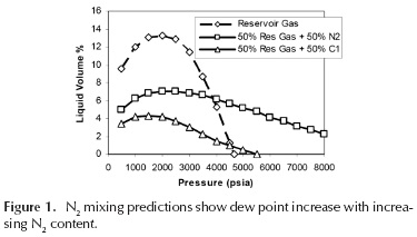
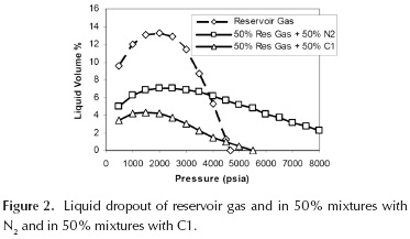
It was pointed to concern how adding N2 will increase liquid dropout and reduce condensate recovery. However, it was concluded that at reservoir pressures of less than 4,000 psi, which is near current conditions of target condensate reservoir in Abu Dhabi, a mixture of N2 and reservoir gas has less liquid dropout than pure reservoir gas. A mixture of lean hydrocarbon gas and reservoir gas has less liquid dropout than a mixture of N2 and reservoir gas, but the difference is relatively small at reservoir abandonment pressures. This is explained by Figures 1 and 2 by Linderman et al. (2008).
-
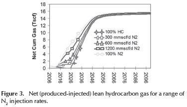
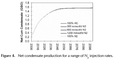
Injection of N2 for varying nitrogen/hydrocarbon ratios in a large condensate reservoir was simulated. The study has shown that N2 injection improves gas and NGL recovery with only a small reduction (≤ 1 % in condensate recovery relative to 100 % hydrocarbon gas injection. The research concludes that overall hydrocarbon recovery on an oil equivalent barrel basis is improved due to higher ultimate recovery of reservoir gas. This is further explained by Figures 3 and 4 by Linderman et al. (2008). Such conclusion failed to relate to Abu Dhabi's economic environment where condensate cracking products are sold at market values while gas is subsidized at a flat rate of nearly a dollar per each million British Thermal Unit (BTU).
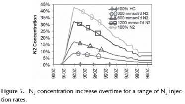
-
It was also found that N2 concentration in the produced gas depends on N2 injection rate and the duration of cycling. As the injection rate of N2 increases, the concentration of N2 in the produced gas stream also increases. N2 concentration climbs over time until blowdown begins when it starts to decrease due to drainage of gas from the areas upswept with N2 injection. This is visually illustrated in Figure 5 from Linderman et al. (2008).
-
It was also pointed out that risks associated with the impact of thief zones (regardless if it is lean gas or N2 injection) may lead to significant bypassing, potentially reducing condensate recovery as well as resulting in an earlier breakthrough and a rapid increase in N2 concentration in the produced gas.
-
N2 injection was also compared to CO2 injection. The latter has produced less net cumulative gas but, nonetheless, condensate production was higher.
Reservoirs of N2 gas substitution potential in Abu Dhabi include: (a) Gas cap reservoirs (undersaturated oil reservoirs with gas phase at the top of the structure) and oil rim reservoirs that suffered rapid pressure decline because of high gas production from the gas cap reducing the ultimate recovery. N2 can be injected into the gas caps, re-pressurizing the reservoir and potentially increasing the recovery of liquids, while the produced hydrocarbon gas can be used for domestic consumption.
(b) Gas condensate reservoirs that are being recycled with hydrocarbon gas to increase condensate recovery. Natural gas injection can be substituted either completely or partially. Reservoirs of such type may be considered the largest opportunities for gas substitution in Abu Dhabi.
Several factors are used to determine which reservoirs are most attractive for N2 substitution. Cther alternatives would be preferred if N2 injection leads to an increase in liquids recovery. Larger opportunities in terms of injection rates as well as development synergies (several reservoirs under one field allowing centralized facilities and reducing distribution cost) are the most cost effective, as they may achieve economies of scale.
Some fields in Abu Dhabi include gas condensate reservoirs as well as gas cap reservoirs. A phased N2 generation and injection development can be implemented where capacities are added gradually to meet pressure maintenance requirements. When blowdown of gas condensate reservoir begins, capacity can be diverted to other reservoirs. This approach will provide flexibility, optimization and enabling long term use of N2 injection facilities.
Managing Nitrogen Breakthrough
Any substitution gas, including N2, will inevitably breakthrough in the produced gas. As a result, the volume of substituted/freed hydrocarbon gas will gradually decrease with the increase of N2 production after breakthrough. In other words, the sales gas product will move out of specifications and the capacity of various product streams may be reduced.
Options for managing N2 in the product gas include the following:
-
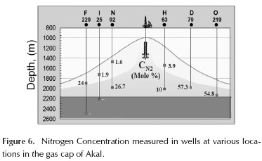
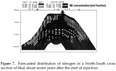
Delaying N2 breakthrough that can be, first, achieved by better understanding the way and the pattern in which N2 is distributed in the gas accumulation. This can be capitalized upon by proper placement of production wells. Rodriguez and Sanches (2004), Rodriguez et al. (2005) and Vazquez et al. (2014), have shown that N2 injection in the gas cap of Akal in the Cantarell project resulted in a segregation of N2 within the gas. N2 was distributed in a cone shape, which can be explained by the density difference between N2 and cap gas. Measurements of N2 concentrations have resulted in higher readings closer to the gasoil contact, as shown in Figure 6 by Rodriguez et al. (2005). Smaller values approaching original N2 concentrations are obtained as we move up. This verified pervious predictions by reservoir simulation studies, as it may be seen in Figure 7 by Rodriguez et al. (2004). This could have helped to put a better development plan which considers delaying N2 breakthrough. In N2 substitution projects where capitalizing on existing infrastructure is a requirement, drilling new wells to enhance the scheme should be assessed against the impact of N2 breakthrough on the facilities.
-
Installing N2 rejection units (NRUs) to remove N2 from the produced gas. Recovered N2 may be re-injected, which may reduce the demand for N2 from the air separation plant, assuming that the supply rate remains flat. The cryogenic N2 rejection is of considerable industry experience among separation methods. Hale and Lokhandwala (2004) introduced good comparisons between N2 rejection technologies. Only Cryogenic Distillation units have been employed for capacities over 100 MMscfd. Cryogenic Distillation has a >95 % Hydrocarbon Recovery. Yet, with respect to flexibility to N2 content in the feed gas stream, NRUs cannot adjust to significant changes in feed gas composition. Bauer (2009) suggests a pure N2 recycle compressor to offset such changes. The compressor will be fully loaded at the start of the plant's life and is then turned down continuously as soon as the N2 concentration in the feed stream increases. The Hannibal Gas Plant of British Gas Tunisia (Jones et al., 1999) uses cryogenic distillation to reduce the N2 content of the feed gas from 16.9 % of N2 to the sales-gas specification of 6.5 %. Operating experiences are given by Jones et al. (1999) and Howard (1998). An alternative to reduce the required capacity of NRU is to bypass part of the feed gas stream around the NRU and blend that with the NRU's product gas. At the beginning of the plant's life, 100 % of the feed gas may be bypassed. However, bypassing will significantly drop as N2 starts to breakthrough until it reaches low percentages above those in which the blended residue gas will go below LHV (Low Heat Value) specification. Thus, a meaningful reduction in the NRU size may not be necessarily achieved, and the unit may need to be designed for the full residue gas throughout.
-
Residue gas can be recycled back to condensate reservoir while cutting the import of gas used to make up for shrinkage resulting from the extraction of liquids. N2 rejection will not be required as re-injection does not have N2 lower limit constrain and make-up gas, that is made available to the sales network and is free from industrial N2 content. In case extra gas supply is required, residue gas of lower grade can be extracted from the recycled stream, which may have a minimum impact on the sales gas pool.
-
Continuing to add make-up gas to the re-injected residue gas to alleviate the reservoir's contamination with N2 can be an alternative for N2 rejection. An equivalent amount of residue gas can be extracted from the same train to the consumer's network of higher gas quality.
-
As previously stated, if residue gas with higher N2 percentage was re-injected, then the effect of below spec LHV would not be an issue. Thus, N2 can be injected into a segment of the reservoir limiting the contamination with N2 to that segment. If production from the same part was processed in an isolated gas processing plant and recycled back to the same segment, gas production from the rest of the reservoir could be routed to a separate train and processed normally, and N2 rejection requirement will not just be significantly delayed, but will have to be designed for lower capacity, compared to full field production. This will improve the economics over the life cycle of the N2 substitution project. The main assumption, and challenge, is to keep N2 confined within that segment of the reservoir.
-
Residue gas will be brought below specification at higher N2 breakthrough percentage in NGL plants with lower ethane recovery that aim at optimizing methane production. In other words, it will take longer for such plants to start suffering deterioration of residue gas quality. Rerouting the N2 rich production to low ethane recovery plants or putting NGL plant into low Ethane recovery (Ethane rejection mode) would counteract the deteriorating impact of N2 breakthrough on LHV. A significant reduction in Ethane recovery would be necessary to achieve a meaningful deferral of the rejection unit's installation. Ethane is normally fed into a petrochemical complex in order to produce polyolefins (plastics).
-
Spiking of NGLs or injection of LPGs. At the gas processing side, blending of NGLs into residue gas product from gas plant to adjust the LHV will lead to high cumulative liquid product losses. Moreover, hydrocarbon dew point of the sales gas maybe exceeded hindering the transportation of gas in pipelines. This can be used only as a short term strategy to alleviate the impact of early N2 breakthrough. At the consumer side, LPG injection may be considered. LPG injection is common in Japan where the heating value specification for power stations and industries is high. When imported LNG is nearly pure methane, LPG storage and injection facility must be available for interchangea-bility purposes.
-
Isolation of produced gas from other sales gas, may be used at specific applications that can tolerate lower BTU gas or modify existing power plants to use lower BTU gas. Boilers are more forgiving to low BTU gas with higher N2 content. Low BTU gas turbines can also be utilized to generate self-captive power at site using rich N2 fuel gas. Yet, turbines manufacturers must be consulted to check if the existing units are satisfactory for the reduced BTU service.
-
As it has been previously pointed out, mixing effects of gas networks should be considered. If the gas plant supplies sales gas to a manifold/pool at which the gas comingles with up to specs or even higher LHV streams, then LHV specifications can be relaxed and the corresponding N2 percentage increase may be accepted.
-
N2 is not the only inert in the gas stream and the requirement of N2 rejection can be further delayed by targeting reducing CO2 content via increasing the rate of acid gas removal.
Case Study: Managing Breakthrough in Abu Dhabi N2 Injection Project
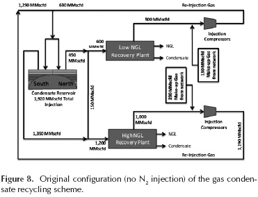
The first N2 injection project in Abu Dhabi is on a comparable scale with the largest N2 injection project in the world in Cantarell, Mexico. Significant quantities of N2 will be injected into a gas condensate reservoir, contrary to a gas cap in the Cantarell, feeding two gas processing plants: Cne of them is of higher NGL recovery than the other and will be referred to as the "High NGL Recovery Plant". The other plant will be referred to as the "Low NGL Recovery Plant". N2 will be approximately 25 % of the gas injected and, after a period, this N2 will start to build up in the produced hydrocarbon streams feeding the two gas processing plants. The level at which the N2 is expected to start affecting the normal operations of the gas processing plant is investigated. Above this level, the product sales gas is expected to move out of specification and the capacity of various product streams may be reduced. The original configuration of gas condensate recycling scheme, i.e. no N2 injection, is shown in Figure 8. Make-up gas imports from the sales gas network is required to complete the injection requirements as the residue gas loses volume after condensate and NGL recovery. Feed gas volumes to both plants exclude water content, yet the same is accounted for in the injection volumes.
In the scenarios discussed, the subsurface simulation model does not recognize N2 content increase in the re-injected gas stream evaluated by the surface simulator which was produced later. An integrated surface-subsurface simulation should be carried out. This is not part of this research; however, it is qualitatively discussed.
It must be noted that such analysis was made at an early stage of Abu Dhabi's N2 injection project, specifically based on the data and knowledge available by end of 2008. Several deterministic factors such as the distribution of the trunk lines from the north and south zones of the reservoir to the High or Low NGL Recovery Plants, impacting the simulation runs, may have been modified altering the N2 concentration in the feed streams. We thus recommend adopting only the methodology explained in this research but rebuilding the cases depending on the final project setup, as agreed by the upstream and downstream operators.
The final project will probably adopt a combination of the "All Field and Isolated" scenarios to meet a short term sales gas shortage requirement, and thus a new reservoir and plant simulations combined for both scenarios will be required. The Isolated Scenario requires more implementation time as it requires long lead new pure N2 compressors. This simulation run was not carried out for this case either, and will not be discussed.
Two cases for N2 breakthrough were simulated. The main purpose of this exercise is to select the production scenario with least impact on production rates and specification, which will reduce or eliminate any required changes to the gas processing facilities.
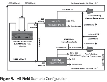
Case #1: The All Field Scenario
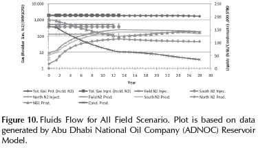
In this scenario, 500 MMscfd of N2 are mixed with residue gas and injected to all parts of the reservoir, and the produced gas is fed to both gas processing plants. Figure 9 demonstrates this scenario, which will be referred to as the "All Field Scenario". Figures 10 to 12 were generated from independent subsurface and surface simulations of this scenario, as mentioned earlier. Note that N2 concentration to both plants is equal as production from north and south zones of the reservoir is commingled before being distributed to each plant according to its allowing capacity. Cnly modification works for natural gas compressors will be required to take in 25 % of N2, constrained by the limitations of additional flow and power requirements as a result of increased molecular weight.
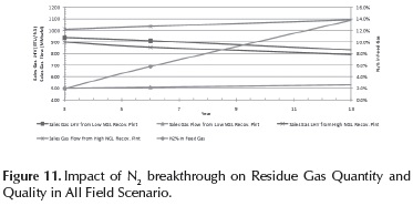
As it would be expected, plant simulation has shown that as the N2 content of the feed gas to both plants increases, the product gas LHV and both NGL and Condensate production rates decrease. The High NGL Recovery residue gas has a lower heating value. Increasing the N2 content further decreases the sales gas heating value, and therefore, as the N2 content of the produced gas from condensate reservoir increases, the sales gas produced from this plant could go off-spec earlier than lower NGL recovery plant.
Figure 11 shows the effects on LHV by increasing N2 content. The gas LHV falls below the 900 BTU/ft3 specification after seven years for Low NGL Recovery Plant, but for High NGL Recovery Plant this point is reached as early as three years after starting injection. The need for N2 rejection facilities is therefore after three years for High NGL Recovery Plant at and above 2 mol % of the 1,200 MMscfd inlet feed gas, and after seven years for Low NGL Recovery Plant at 7.1 mol % of the 600 MMscfd inlet feed. Relaxation of LHV to 850 BTU/ft3 may also be considered by taking into account the mixing effect at the sales gas network. Then, the requirement for any N2 rejection plants may be differed by three years for High NGL Recovery Plant and four years for Low NGL Recovery Plant.
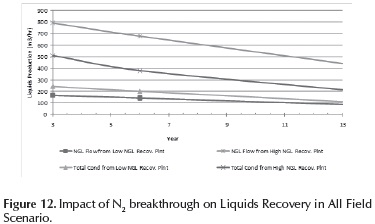
Figure 11 also demonstrates how gas rates through Low NGL Recovery Plant and High NGL Recovery Plant generally increase over the injection period. Figure 12 shows that NGL and Condensate production rates fall as N2 injection proceeds.
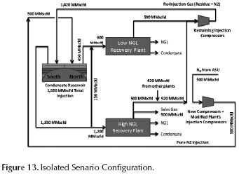
Case #2: The Isolated Scenario
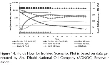
In this scenario, as explained in Figure 13, 500 MMscfd of N2 are injected to the northern part of the field. The production of the same part of the field will be segregated and fed to the gas processing plant of lower NGL recovery, with the southern part feeding the High NGL Recovery Plant. This scenario will be referred to as the "Isolated Scenario". Figures 14 to 16 were generated from independent subsurface and surface simulations of this scenario, as mentioned earlier. Note that N2 concentration to the Low NGL Recovery Plant is based on north zone production in addition to the 150 MMscfd stream diverted from south zone. New pure N2 compressor, capable of handling the increased molecular weight, increased mass flow rate and increased power requirement as a result of addition of N2, will be required.
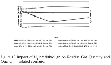
As it would be expected, plant simulation has shown that as the N2 content of the feed gas to both plants increases, the product gas LHV and both NGL and Condensate production rates decrease. Figure 15 shows the effects on LHV by increasing N2 content. The gas LHV falls below the 900 BTU/ft3 specification just after three years for Low NGL Recovery Plant and nine years for High NGL Recovery Plant. Although the fall below specification for Low NGL Recovery Plant occurs earlier, this gas can be used for re-injection into the reservoir, a use for which the LHV specification is irrelevant. This would preclude the need for any N2 rejection facilities for the Low NGL Recovery Plant.
However, N2 re-injection may not be possible to the north part due to unavailable injection capacity occupied by N2 supplies from ASU. Otherwise, re-injection can be directed to the southern zone. N2 content in the recycled gas was not accounted for in the reservoir model, as if an NRU was installed to remove any N2 content above the level that will bring LHV below 900 BTU/ft3. Even in this latter hypothetical assumption, rejected N2 should be injected at some reservoir to create a value, as the idea of simply venting N2, which was bought or generated at a cost, would not be acceptable.
If re-injection into southern zone was accounted for, the impact of the high NGL recovery plant will be higher, N2 will breakthrough at higher rate and sales gas LHV will be brought below specifications earlier. A gradual increase of N2 content in the recycled gas to the south zone which will reach ∼ 200 MMscfd of N2 by year 2012 before starting to decline, will have lower impact on the High NGL Recovery Train than the All Field Scenario which injects 370 MMscfd of N2 into the southern zone from the beginning of injection.
N2 rejection facilities will still be needed after nine years for the High NGL Recovery Plant at and above 2.1 N2 mol % of the 1,200 MMscfd inlet feed. However, if the mixing effect of the sales network was considered, LHV specification may be relaxed to 850 BTU/ft3 and N2 rejection for High NGL Recovery Plant would not be required. Even if N2 rejection was installed, the plant capacity would at least be reduced compared to the All Field Scenario.
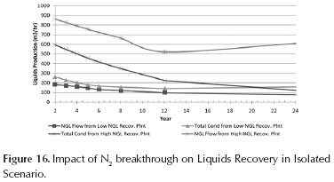
Figure 15 also demonstrates how gas rates within Low and High NGL Recovery Plants generally increase over the injection period. Figure 16 shows that the quantities of NGL and Condensate produced, slowly decrease as the N2 content of the feed gas increases. This will reduce the revenue stream from the plants. The levels of Condensate and NGL fluids decrease generally in both Low and High NGL Recovery Plants.
Discussion of findings
A comparison of both scenarios shows that the Isolated Scenario has the least effect on the reservoir and production trains. The Isolated Scenario has a more limited effect on product specifications and quantities as the effect of the N2 is limited to part of the reservoir. For the All Field Scenario, the residue gas LHV falls below specification sooner in the High NGL Recovery Plant of more significance in terms of liquids production, and N2 Rejection is required earlier than the Isolated Scenario and at a larger capacity as well. This Rejection Plant will be a major cost addition. It is recommended to relax the sales gas LHV specification considering the mixing effect at the sales gas network and with consultation of gas consumers. In the Isolated Scenario, this may lead to entirely exclude N2 rejection.
The increase in N2 content in the gas feeding both Low and High NGL Recovery Plants results in changes to gas and liquid flows in various areas of the plants. More detailed work is required to ascertain if any changes to existing equipment are needed.
The advantages of the Isolated Scenario, especially in terms of eliminating N2 rejection requirements, should justify the cost of the new compression system. This might also be regarded as a long term investment, as the same compression equipment can be utilized when the injection is diverted to other reservoirs after blowdown, maximizing equipment utilization.
Nitrogen Rejection and Alternatives
As mentioned above, there would be a potential requirement for the rejection of N2 to maintain the sales gas LHV above its specification value. Cryogenic Separation may be identified as the most economic rejection technology to operate at the aforementioned capacities, and has been demonstrated in operation in comparable train sizes. Plants of similar size using Cryogenic Separation technology were installed in the Cantarell N2 Injection project. Other technologies are proven but not for such capacities.
As discussed earlier, adoption of the Isolated Scenario for N2 injection is recommended to defer, eliminate or at least reduce the capital expenditure associated with installing NRUs. Differing NRUs will also allow the technology to develop further, more plants to be built elsewhere, operating plant capacities to increase, and other companies to gain operating experience. In addition, this permits several years of reservoir performance monitoring against the predictions to assess the impact of N2 breakthrough more accurately.
On the other hand, the All Field Scenario results in a much earlier requirement for installing N2 Rejection.
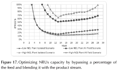
In case NRU installation was a must, bypassing of a percentage of the NRU feed was evaluated to optimize the NRU capacity requirement. The target was to have N2 content of the blended streams after the NRU equal to that when LHV starts to drop below specification. Figure 17 shows the result of the analysis. It can be concluded that bypassing is more effective for the High NGL Recovery Plant at the Isolated Scenario as well as for Low NGL Recovery Plant at the All Field Scenario, where the minimum bypass percentages are 63 % and 51 %, respectively.
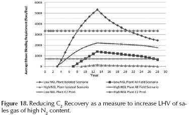
Reducing C2 recovery was also evaluated as a mean to increasing residue gas heating value and as an alternative to NRUs. As shown in Figure 18, the C2 production of Low NGL Recovery Plant will hardly meet the blending requirements for the first two (2) years after LHV goes below specifications for the Isolated Scenario and the first four years in the All Field Scenario. High Recovery Plant current C2 production recovery levels may cover the blending requirements for both cases. However, this option may not be feasible considering the need for C2 as feedstock for petrochemical developments.
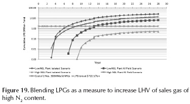
LPG blending was also examined. Figure 19 shows the cumulative injection requirements and compares that to the cost of two 300 MMscfd inlet feed capacity NRUs. We can conclude that LPG injection would benefit as an interim or short term solution and may be completive on the long term only at the High NGL Recovery Plant in the Isolated Scenario.
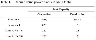
We have also looked at gas consumers that may be impacted the least by the increase in N2 content in the sales gas. Namely, thermal power plants, i.e. steam turbines power plants, where steam is generated by boiling water. Table 1 lists power stations of this type in Abu Dhabi. Umm Al Nar units are retiring soon, and Taweelah B is supplied by a different operator, Dolphin Energy Limited. Taweelah B gaseous fuel requirements are nearly 110 MMscfd as per Abu Dhabi Water and Electricity Company statistical report for the period between 1998 and 2007, and thus will not be able to accommodate a meaningful portion of the residue gas stream of higher N2 percentage.
The targeted daily sales gas quantities to be freed are nearly one fifth of 2009 average sales gas production. Assuming the sales gas network has an LHV of 905 to 910 BTU/ft3, LHV speciications for sales gas from High NGL Recovery Plant can be relaxed to 875-850 BT/SCF. For such values, and recycling the Low NGL Recovery Plant residue production, NRU will be of no need to bring the LHV of High NGL Recovery Plant's residue gas back to specifications. For the All Field scenario, this result defers the NRU requirement for the High NGL Recovery plant for only three years.
Conclusions and Recommendations
Non-hydrocarbons injection may bring forward the opportunity to exploit lean gas earlier before the start of reservoir blowdown.
It is feasible and recommended to defer the breakthrough of N2 and alleviate its impact when it happens on production rates and specifications, deferring and perhaps eliminating the need for N2 rejection, and improving the economic viability of the overall N2 injection scheme.
Assuming gas recycling is adopted and no NRUs are planned, an integrated surface-subsurface simulation should be carried out. This will define the composition of the re-injection stream and give corrected N2 breakthrough profiles.
The Isolated Scenario is recommended as it has a more limited effect on product specifications and quantities, smaller and later N2 rejection requirement and can be invested in future N2 injection projects.
It is recommended to relax the sales gas LHV specification considering the mixing effect at the sale gas export system to eliminate the NRU requirement in the Isolated Scenario, provided that Low NGL recovery plant residue gas is recycled back to the reservoir.
If N2 rejection for High NGL Recovery plant in the Isolated Scenario cannot be entirely eliminated, then it can at least be further deferred by spiking of NGLs, and its capacity can be reduced via bypassing a portion of the contaminated feed.
The overall impact of N2 injection on hydrocarbons recovery should be assessed in terms of net present value NPV rather than the barrels of oil equivalent BOE, considering the flat price of sales gas.
An extensive data collection/sampling program should be launched in order to: a) Extrapolate the residue gas breakthrough behavior to that of N2, b) to verify the accuracy of simulation runs after N2 injection starts. Such profiles are necessary for investment decisions associated with NRU requirement.
A market price should be given to natural gas utilization in the upstream oil and gas operations in Abu Dhabi, which is free under current jurisdictions. Only then, natural gas injection will be optimized, ongoing over injection will cease, and alternatives such as N2 will be more seriously considered.
Acknowledgements
This research program has been established at the Petroleum Institute, Abu Dhabi. The authors wish to acknowledge the support for this research project from our sponsors, ADNOC (Abu Dhabi National Oil Company) and OPCO's, Abu Dhabi, UAE.
References
Abdulwahab, H. (2010). Recovery of Tail Gas from Sulphur Recovery Units for injection into Oil & Gas Reservoirs. Paper proposal to Abu Dhabi International Petroleum Exhibition and Conference. [ Links ]
Bauer, H. (2009). Cryogenic Nitrogen Rejection, a Versatile Answer to Present Challenges. GPA-GCC Chapter, 17th Annual Technical Conference. Abu Dhabi, UAE. [ Links ]
Donohoe, C., Buchanan, R. (1981). Economic Evaluation of Cycling Gas-Condensate Reservoirs with Nitrogen. Journal of Petroleum Technology, 33(2), 263-270. DOI: 10.2118/7494-PA. [ Links ]
Hale, P., Lokhandwala K. (2004). Advances in Membrane Materials Provide New Gas Processing Solutions. Proceedings of the Laurance Reid Gas Conditioning Conference. Norman, OK, 165. [ Links ]
Howard, I. (1998). Hannibal's Experiences. Proceedings of the Laurance Reid Gas Conditioning Conference. Norman, OK, 194. [ Links ]
Jones, S., Lee, S., Evans, M., Chen, R. (1999). Simultaneous Removal of Water and BTEX from Feed Gas for a Cryogenic Plant. Proceedings of the 78th Annual Convention of the Gas Processors Association. Tulsa, OK, 108. [ Links ]
Linderman, J., Al-Jenabi, F., Ghoori, S., Putney, K., Lawrence, J., Gallet M. Hohensee, K. (2008). Feasibility Study Of Substituting Nitrogen For Hydrocarbon In A Gas Recycle Condensate Reservoir. SPE 117952-MS, Abu Dhabi International Petroleum Exhibition and Conference. Abu Dhabi, UAE. DOI: 10.2118/117952-MS. [ Links ]
Rodriguez, F., Sancehs, J., Astudillo, A. (2005). Nitrogen Injection in the Cantrell Complex: Results after four years of operations. SPE 97385-MS, SPE Latin American and Caribbean Petroleum Engineering Conference. RJ, Brazil. DOI: 10.21 18/90288-MS. [ Links ]
Rodriguez, F., Sancehs, J., Galindo-Nava, A. (2004). Mechanisms and Main Parameters Affecting Nitrogen Distribution in the Gas Cap of the Supergiant Akal Reservoir in the Can-tarell Complex. SPE 90288-MS, SPE Annual Technical Conference and Exhibition. Houston, Texas: U.S.A. [ Links ]
Subero. (2009). Numerical Modelling of Nitrogen injection in Gas Condensate Reservoir (Unpublished M.Sc. thesis). College of Engineering and Mineral Resources. West Virginia University. Morgantown, WV: U.S.A. [ Links ]
Sanger, P., Hagoort, J. (1998) Recovery of Gas Condensate by Nitrogen Injection Compared With Methane Injection. SPE Journal, 3(1), 26-33. DOI: 10.21 18/30795-PA. [ Links ]
Siregar, S., Hagoort, J., Ronde H. (1992). Nitrogen Injection vs. Gas Cycling in Rich Retrograde Condensate-Gas Reservoirs. SPE 22360-MS, International Meeting on Petroleum Engineering,. Beijing, China. DOI: 10.21 18/22360-MS. [ Links ]
Tiwari S., Kumar, M. (2001). Nitrogen Injection for Simultaneous Exploitation of Gas Cap. SPE 68169-MS, SPE Middle East Oil Show. Bahrain. DOI: 10.2118/68169-MS. [ Links ]
Rodriguez, F., Sanchez, J. Austudillo, A. (2005). Nitrogen Injection in the Cantarell Complex: Results After Four Years of Operation. SPE Latin American and Caribbean Petroleum Engineering Conference. RJ, Brazil. [ Links ]
CAJB Monitoring Team. (July 2013). Annual Evaluation of the Nitrogen Injection Project. [ Links ]
Vazquez, A.J., Guerrero, R. Ancona, M.A., Hemandez, R. Colin, G. (2014). Immiscible Nitrogen Injection: A Challenge Experience on Depleted Naturally Fractured Reservoir. SPE-171816-MS SPE - ADIPEC 2014. Abu Dhabi, DOI: 10.2118/171816-MS. [ Links ]

