


Services on Demand
Journal
Article
 English (pdf)
 Article in xml format
 Article references
 Send this article by e-mail
Indicators
-
 Cited by SciELO
 -
 Access statistics
Related links
-
 Cited by Google
 -
 Similars in
SciELO
Similars in
SciELO -
 Similars in Google
Share

 Permalink
Ingeniería e Investigación
Print version ISSN 0120-5609
Ing. Investig. vol.36 no.1 Bogotá Jan./June 2016
https://doi.org/10.15446/ing.investig.v36n1.53191
DOI: http://dx.doi.org/10.15446/ing.investig.v36n1.53191
Design of a 2DOF parallel mechanism to assist therapies for knee rehabilitation
Diseño de un mecanismo paralelo de 2 grados de libertad para asistir terapias de rehabilitación de la rodilla
B. D. M. Chaparro-Rico1, and E. Castillo-Castañeda2
1 Betsy Dayana Marcela Chaparro Rico: Electronic Engineer, Unisangil, Colombia. Master in Advanced Technology, National Polytechnic Institute, Mexico. Affiliation: Ph. D. student in Advanced Technology, National Polytechnic Institute - CICATA Queretaro, Queretaro: Qro., Mexico.
Email: betsychaparro@hotmail.com.
2 Eduardo Castillo Castaneda. Mechanical-Electrical Engineer, National Autonomous University of Mexico, Mexico. Ph.D. in Automatic Control, Grenoble Institute of Technology, France. Affiliation: Professor, National Polytechnic In-stitute-CICATA Queretaro, Queretaro, Qro., Mexico.
Email: ecast63@yahoo.com.
How to cite: Chaparro-Rico, B. D. M., & Castillo-Castañeda, E. (2016). Design of a 2DOF parallel mechanism to assist therapies for knee rehabilitation. Ingeniería e Investigación, 36(1), 98-104. DOI: http://dx.doi.org/10.15446/ing.investig.v36n1.53191.
ABSTRACT
This paper presents a knee rehabilitation device to reproduce four exercises generally used in the rehabilitation therapies. The device consists of a mechanical structure based on a 2 DOF parallel mechanism, a controller with PIC-SERVO motion control boards, and a GUI that commands the device to reproduce the rehabilitation exercises. The position kinematic analysis of the mechanism is developed as well as its dimensioning synthesis to cover various leg sizes. This work proposes a technological alternative with significant advantages that responds to the global need for improving physical knee rehabilitation process. A prototype was manufactured and its mobility was validated using a mannequin.
Keywords: Knee rehabilitation, parallel mechanism, rehabilitation device.
RESUMEN
Este artículo presenta un dispositivo para la rehabilitación de la rodilla que reproduce cuatro ejercicios generalmente usados en las terapias de rehabilitación. El dispositivo consiste en una estructura mecánica basada en un mecanismo de 2 grados de libertad, un controlador con tarjetas de control del movimiento PIC-SERVO, y una GUI que comanda el dispositivo para reproducir los ejercicios de rehabilitación. Fue desarrollado el análisis de cinemática de posición del mecanismo, así como también la síntesis de dimensionamiento para cubrir varias dimensiones de piernas. Este trabajo propone una alternativa tecnológica con ventajas significativas que responden a la necesidad global de mejorar el proceso de rehabilitación física de la rodilla. Un prototipo fue construido y su movilidad fue validada usando un maniquí.
Palabras clave: Rehabilitación de la rodilla, mecanismos paralelos, dispositivo de rehabilitación.
Received: September 23 rd 2015 Accepted: February 11th 2016
Introduction
Simple mechanisms have been developed around the assistance of knee rehabilitation to facilitate the realization of some movement, for example, Koch (2007), patented in the United States, a simple device for knee rehabilitation consisting mainly of a foot support; the device is actuated manually pulling the foot towards the knee by a leash to increase range of motion after knee injury (Figure 1a). Another manual mechanism for rehabilitation, more complex than that of Stanley, was developed by Hall (2011); it can be used in various stages of knee rehabilitation and can be used for the patient without therapist assistance, and its length is also adjustable (Figure 1b). Through the mechanism, the patient gets the knee flexoextension by himself. Weiner (2010) presents a device to increase the knee range motion (Figure 1c). When the mechanism is used, the patient's knee rotates causing flexoextension.
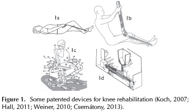
Chang-Soo and Jung-Soo (2012) present a portable apparatus that gradually increases the amplitude of motion of the knee. Carlson and Perry (2013) designed a portable device for knee after surgery. On the other hand, Csernátony (2013) proposes a continuous passive motion device for knee rehabilitation, which by holding the patient's foot causes the leg movement in the vertical plane (see Figure 1d). Most of these devices allow a limited number of rehabilitation exercises and some of them require the use of the patient's own strength, which is not convenient for elderly people. Akdogan and Adli (2011) proposed a device with reduced workspace called Physiotherabot that uses force sensors to measure patient efforts during the exercises. In Japan, Taisuke et al. (1999) developed TEM (Therapeutic Exercise Machine) to decrease muscle spasticity by continuous passive motion for lower limb; the device memorize motions guided by a physiotherapist.
The device presented in this paper is based on a five-bar linkage, hereafter referred as a 2 DOF parallel mechanism, fully automated to assist the therapist during the knee rehabilitation. The main feature of parallel mechanisms is that the actuators are not in the joints but in the robot base; this greatly simplifies the design and manufacture of the device. The resulting device offers advantages over other devices such as, among others, the ability to reproduce multiple exercises in a single apparatus. The end effector of the mechanism guides the patient's legs in the reproduction of exercises for knee rehabilitation.
Selected Exercises
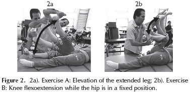
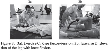
According to specialists from the CRIQ (Integral Rehabilitation Center of Queretaro, Mexico) and to scientific literature review, four exercises for knee rehabilitation were selected to be reproduced by the mechanism: exercise A, presented in Figure 2a, works hip flexoextension that involves lifting the extended leg1; exercise B consists in the leg flexoextension rotating the knee joint, as shown in Figure 2b, while the hip is in a fixed position; exercise C (Figure 3a) causes the joint motion of both the knee and the hip following an horizontal trajectory with the foot; exercise D (Figure 3b) works a greater range of motion of the knee and hip joints and is performed by elevating the leg to the abdomen while the knee is flexed.
The four exercises are commonly used in protocols for rehabilitation as: knee replacement (AAOS, 2009; Schoen, 2000), after an arthroscopy (AAOS, 2000), after a knee surgery (AAOS, 2012), to avoid knee pain (Arthritis Research UK, 2013), and injuries of the anterior cruciate ligament. The trajectories of each exercise were characterized using a simplified model of the leg, assuming that the leg motion occurs only on the vertical plane. This characterization must be independent of the size of the patient's leg.
Characterization of Trajectories
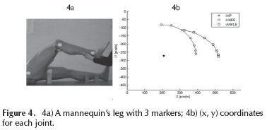
A method of image processing was used to acquire the joint trajectories related with each exercise: three markers were placed on the ankle joints while a video was recorded and decomposed into 30 frames per second, to extract (x, y) coordinates of the center of each marker. As an example, Figure 4a shows the experimental set up to extract joint trajectory of exercise D using a mannequin; Figure 4b presents the resulting trajectory in pixels for each joint (hip, knee, and ankle); only (x, y) coordinates of ankle joint were considered. The (x, y) coordinates are used to find the angular exercise behavior by using the inverse geometric model of the leg.
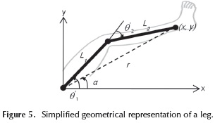
Inverse geometric model of the leg
Figure 5 shows a simplified geometric representation of the leg, where link L1 represents the femur and link L2 represents the tibia (Asada, 2005). The inputs of the model are (x, y) and the unknown variables are the angles θ'1 and θ'2, which are the hip and knee joints respectively. The trajectories are characterized according to the temporal behavior of these two angles.
If lengths L1 and L2 are known, the inverse geometric model is given by:
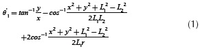
Where:
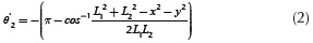
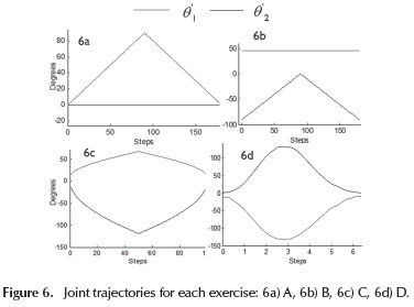
Joint behaviour of the trajectories
Through the inverse geometric model of the leg, using the numerical values of L1 and L2 of the mannequin and the coordinates (x, y) of the ankle, the joint behavior of each exercise was found; see Figures 6a-6d. It is assumed that these joint trajectories are independent of the person height and therefore are considered as the trajectory characterization of the exercises.
Required workspace to cover the four trajectories
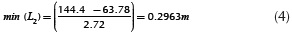
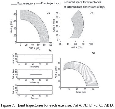
From the behavior of θ'1 and θ'2the Cartesian trajectories for the minimum and maximum heights were obtained, and the corresponding graphs allow to determine the workspace required for reproduction of the exercises. In order to determine the numerical values of the lengths of the links L1 and L2, the minimum and maximum heights located between the percentiles 5 and 95 were selected corresponding to the Mexican adult population (Avila, Prado & Gonzalez, 2001), a range of 1.444 m to 1.813 m. Based on these heights, the formulas for the reconstruction of height were applied to find the size of the femur and tibia (Krenzer, 2006), obtaining the values for the maximum and minimum value of L1 and L2.
Minimum height:
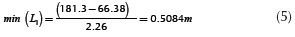
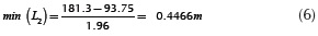
Maximum height:
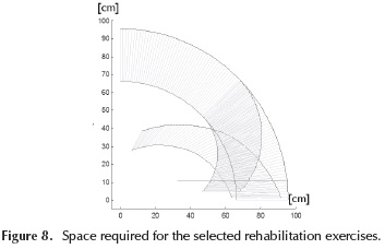
In Figures 7a-7d, the Cartesian behavior is observed for each exercise. The blue graph is the Cartesian trajectory of the longest leg and the red graph of the shorter leg; the cyan area corresponds to trajectories for intermediate dimensions of legs. The required workspace to reproduce the four exercises (Figure 8), considering any size of leg, will be the union of the four workspaces shown in Figure 7.
Design and Construction
Proposed mechanism
From the characterization of the selected exercises, three fundamental requirements were considered to choose the most suitable mechanism:
-
the workspace of the mechanism should cover the space required to reproduce each exercise (see Figure 8);
-
the mechanism should have two degrees of freedom since all selected exercises are performed in a single plane (vertical plane); and
-
the mechanism should be able to reproduce trajectories covering from maximum to minimum leg sizes.
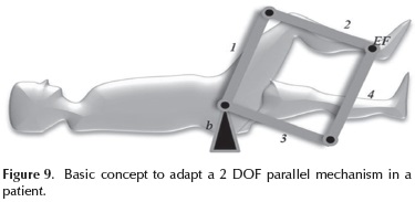
In this paper, a parallel mechanism of 2 DOF with rotational joints is proposed. Parallel mechanisms are characterized by a high rigidity because they eliminate the cantilever configuration, commonly used in serial mechanisms. Figure 9 shows the basic concept of adapting the parallel mechanism in the patient's leg, where numbers 1, 2, 3 and 4 represent the movable links connected by passive rotational joints; EF is the end effector mechanism, which is in charge of supporting and guiding the patient's leg and b is the mechanism's base. Two active joints located at b, drive the mechanism; one is connected to link 1 and the other to link 3.
By applying the Grubler criterion (Hun, 1978) for planar mechanisms, it can be demonstrated that the mechanism has two degrees of freedom.
Forward geometric model
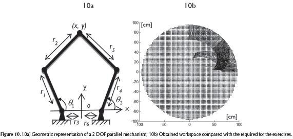
From the geometry of the device (Figure 10a), an implicit solution (see Equation (7) and Equation (8)) of the geometric model was found and the unknown variables x and y were calculated by using symbolic computation in Matlab. Where the other variables of the system are given, θ1 and θ2 are the active joints; r1, r2, r4, r5 are lengths of the respective bars and r3, r6 are the distances between the active joints and the origin of the reference system. The equations of forward and inverse kinematics were validated with Matlab (Xin-Jun, Jinsong & Hao-Jun, 2006).


Inverse geometric model
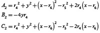
Inverse kinematics was solved explicitly from Equation (7) and Equation (8) as follows:
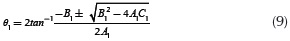
with:
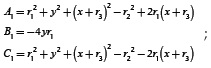
and:
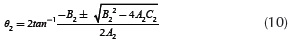
with:
the corresponding workspace can be also obtained. It was verified that the workspace covers the space needed to reproduce the four selected exercises for knee rehabilitation previously characterized.
Dimensional synthesis
Dimensional synthesis consists in determining the length of links r1, r2, r3 and r4; see Figure 10, according to the following conditions: 1) maximize the workspace; 2) cover the required workspace to adapt the mechanism to maximum and minimum size patient's legs. By simulations, in order to maximize the workspace:
-
Links r3 and r6 must match the mechanism base, which means: r3 = r6 = 0
-
The rest of the links should have same lengths, which means: r1 = r4 = r2 = r5
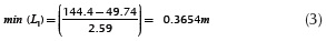
For the second condition, the total length of the extended mechanism (r1+ r2) should be equal to the size of the largest leg (max(L1) + max(L2)), which means:

Additionally, lengths r1 and r2 have the same value, which means: 2r1 = 2r2 = max(L1) + max(L2). Finally, replacing the numerical values for max(L1) and max(L2):

Considering these lengths, the resulting workspace is presented in Figure 10b. This workspace perfectly covers the requirements of the four rehabilitation exercises.
Simulation in MATLAB
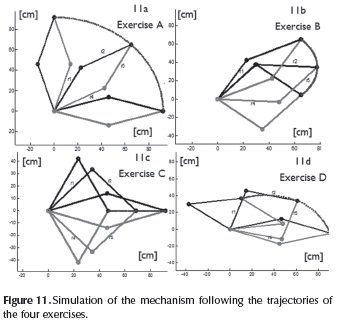
Using MATLAB, simulations were performed to ensure that the mechanism is able to reproduce the four selected trajectories. In Figures 11a-11d, simulations for each exercise are presented. The blue line corresponds to the Cartesian trajectory at the ankle level. The black lines correspond to the upper arm (formed by bars r1, r2) and the red lines to the lower arm (formed by bars r4, r5).
CAD of the device
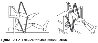
The CAD was performed in INVENTOR, considering the characteristics and dimensions commercially available of the mechanical elements and actuators to be used in the manufacture. The bars are made of aluminium profile BOSCH series 28 No 12-028 which supports up 24.48 kgf/ mm2. The rotational joints are pivot joint from BOSCH 23-015B with load capacity of 76 kgf. The linear actuators are from ELECTRA S24-09A4-06 with load capacity of 11.339 kg that was sufficient for testing the device with a mannequin weighing 2 kg. Figure 12 shows 2 views of the device. CAD simulations helped to find the most convenient location of the base of the 2 DOF parallel mechanism, related to patient's hip position, to ensure that actuators and links do not touch the patient's body during the exercises. In addition, the device can be adapted to persons of different heights merely by setting the end-effector at a predefined distance of the ankle joint.
Construction of the device
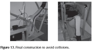
The arms of the mechanism were mounted on the basis, and before assembling the actuators the mobility of the mechanism was verified by manually reproducing each rehabilitation exercise on a subject. Figure 13 shows the final construction; the actuators are located to avoid collisions with subject's legs since one actuator is located on one side of the bed and the other actuator is located on a horizontal support far enough of patient body.
To control the rehabilitation device a cabinet consisting of two PIC-SERVO SC cards and a communication card SSA 485 was assembled. Quadrature incremental encoders are used to close de control loop; each encoder measures the position of each active joint. Further, a GUI was implemented using Visual C++; the GUI enables the user communication with the controller, the Cartesian and joint control modes and the reproduction of exercises A, B, C and D.
Experimental Validation
Reproducing the trajectories
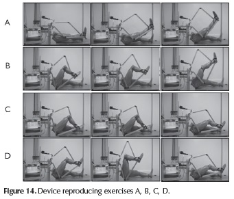
Through C++ programs the trajectories of the selected rehabilitation exercises were reproduced, using the articulated mannequin as a patient. Three images for each exercise of the operating device are shown in Figure 14.
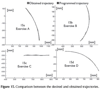
The obtained trajectories were computed using image analysis from a video recorded during exercises execution. Red marks were located on the basis and on the end effector of the mechanism. Figures 15a-15d show the comparative curves of the programmed trajectories (blue) and the obtained trajectories (red). As shown, the device reproduces exercises A, B, C and D for the test mannequin. The variations observed in the obtained trajectory regarding programed trajectory are due to the acquisition method. The parallelism of the camera with respect to the vertical plane, the orientation of the camera, the dimensional conversion pixels to centimeters and the calculation of the center of each mark could cause errors. Adittionally, some vibrations and backlash present in the device could affect the reproduction trajectories.
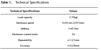
Technical Specifications
Technical specifications of the device are shown in Table 1. The maximum load was obtained by applying load at the ankle level (end effector) until one of the motors reached nominal current (3A). The stiffness was estimated using the maximum load (3.70 kg = 36.38 N) in 5 points within the workspace, where the achieved displacement with and without load was measured. The repeatability and accuracy were calculated using the formulas in the ISO 9283 standard.
Conclusions
A device for knee rehabilitation based on a mechanism of parallel structure was designed, manufactured and controlled, and it is able to reproduce four of the exercises normally used in knee rehabilitation. Until now, tests have been performed using the leg of a mannequin and thereby the sizing of actuators has not been necessary. However, it is important to include a dynamic analysis of the mechanism in order to determine the motor torque in the case of a real leg, as well as considering the study on the effect of the relative location of the patient's hip and the mechanism base from both a kinematics and dynamics point of view. In fact, the mechanism can be oriented in a vertical way with similar resulting workspace. The device allows flexoextension hip, flexoextension knee and simultaneous flexoextension of the hip and knee. The device can play any movement of knee rehabilitation developed in the vertical plane, and it may also be used in patients of any height. The possibility of developing work around this project is opened, dealing particularly with: mechanical design optimization in order to reduce vibration and backlash; refinement of the method of acquisition of the trajectories in order to reduce the error variables introducing parallelism and camera orientation; developing a control method in order to smooth the performance of linear motors; and the exploration of another method of reproducing trajectories of rehabilitation exercises, in order to facilitate the characterization. In the near future, experiments will be performed on healthy people to determine the best strategy to attach the patient's leg, safely and rigidly.
Acknowledgements
Authors thank to CRIQ specialists for their help.
References
AAOS. (2000). Knee Arthroscopy Exercise Cuide. Retrieved from http://orthoinfo.aaos.org/topic.cfm?topic=A00300. [ Links ]
AAOS. (2009). Ejercicio después de reemplazo de rodilla (Knee Replacement Exercises Retrieved from http://orthoinfo.aaos.org/topic.cfm?topic=A00494. [ Links ]
AAOS. (2012). Knee Conditioning Program. Retrieved from http://orthoinfo.aaos.org/topic.cfm?topic=A00664#7. [ Links ]
Akdogan, E. & Arif-Adli, M. (2011). The design and control of a therapeutic exercise robot for lower limb rehabilitation. Mechatronics, 21, 509-522. DOI: 10.1016/j.mechatronics.2011.01.005. [ Links ]
Avila, R., Prado, L. & González, E. (2001). Dimensiones antropométricas de población latinoamericana: dimensiones antropomórficas de la población mexicana. México: Universidad de Guadalajara, Centro de investigaciones en ergonomía. [ Links ]
Arthritis Research UK. (2013). Knee pain exercises. Retrieved from http://www.arthritisresearchuk.org/arthritis-information/conditions/osteoarthritis-of-the-knee/knee-pain-exercises.aspx. [ Links ]
Asada, H. H. (2005). Chapter 4 Planar Kinematics. In lecture notes by Professor Asada, MITOPENCOURSEWARE: Introduction to Robotics (pp. 1-8). United States of America: Massachusetts Institute of Technology. Retrieved from http://ocw.mit.edu/courses/mechanical-engineering/2-12-introduction-to-robotics-fall-2005/lecture-notes/. [ Links ]
Carlson, D. L. & Perry C. M. (2013). Portable Knee Rehabilitation device, Patent No US201301 10013 A1, US. [ Links ]
Chang-Soo, H. & Jung-Soo, H. (2012) Portable Knee rehabilitation exercise apparatus, Patent No WO2012124912 A2, US. [ Links ]
Csernátony Z. (2013). Continuous passive motion device for treatment of the knee joint, Patent No Ep25836656 A2, European patent application. [ Links ]
Hall, J. R. (2011). Knee rehabilitation device, Patent US 2011224585A1, Draper, UT, US. [ Links ]
Hun, K. (1978). Kinematic Geometry of Mechanisms,. UK: Oxford University Press. [ Links ]
Koch, S. B. (2007). Knee rehabilitation device, Patent US 20070149368A1, Nashville, US. [ Links ]
Krenzer, U. (2006). Compendio de Métodos Antropológico Forenses. para la reconstrucción del perfil osteo-biológico, Tomo V, Características Individuales. Guatemala: CAFCA. [ Links ]
Sakaki, T., Okada, S., Okajima, Y. & Tanaka N. (1999).TEM: therapeutic exercise machine for hipand knee joints of spastic patients. Sixth international conference on rehabilitation robotics, ICORR'99. [ Links ]
Schoen, D. C. (2000). Adult Orthopaedic Nursing, 1st edition, Philadelphia: Lip-pincott. [ Links ]
Weiner. J. J. (2010). Device and method for knee joint rehabilitation. Patent No US 7,695,416 B2, United States Patent. [ Links ]
Xin-Jun L., Jinsong W. & Hao-Jun Z. (2006). Optimum design of the 5R symmetrical parallel manipulator with a surrounded and good-condition workspace. Robotics and Autonomous Systems, 54, 221-233. DOI: 10.1016/j.robot.2005.11.002. [ Links ]

