


Services on Demand
Journal
Article
 English (pdf)
 Article in xml format
 Article references
 Send this article by e-mail
Indicators
-
 Cited by SciELO
 -
 Access statistics
Related links
-
 Cited by Google
 -
 Similars in
SciELO
Similars in
SciELO -
 Similars in Google
Share

 Permalink
Ingeniería e Investigación
Print version ISSN 0120-5609
Ing. Investig. vol.36 no.2 Bogotá May/Aug. 2016
https://doi.org/10.15446/ing.investig.v36n2.52517
DOI: http://dx.doi.org/10.15446/ing.investig.v36n2.52517
Method for the multi-criteria optimization of car wheel suspension mechanisms
Método para la optimización multiobjetivo del mecanismo de suspensión de las ruedas de automóviles
Cătălin Alexandru1, and Vlad Totu2
1 PhD in Mechanical Engineering. Affiliation: Full Professor at Department of Product Design, Mechatronics and Environment, Transilvania University of Brasov, Romania. E-mail: calex@unitbv.ro.
2 PhD in Mechanical Engineering. Affiliation: Associate Professor at Department of Product Design, Mechatronics and Environment, Transilvania University of Brasov, Romania. E-mail: totu.vlad@gmail.com.
How to cite: Alexandru, Cátálin., & Totu, V. (2016). Method for the multicriteria optimization of car wheel sus-pension mechanisms. Ingeniería e Investigación, 36(2), 60-67. DOI: 10.15446/ing.investig.v36n2.5251 7.
ABSTRACT
The paper deals with a general method for the multi-criteria optimization of the rear wheels suspension mechanisms in terms of kinematic behavior. The suspension mechanism is decomposed in basic binary links, and the kinematic synthesis is separately performed for each of them. The design variables are the global coordinates of the joint locations on the car body (chassis). The disposing of the joints on the wheel carrier were exclusively established by constructive criteria. The design objectives relate to kinematic position parameters of the wheel (displacements of the wheel centre along longitudinal and transversal directions, and modifications of the wheel axis direction), the optimization goal being to minimize these variations during the wheel travel. A computer program for the kinematic study was developed in C++. The application was performed for the wheel suspension mechanism of a race car.
Keywords: Car, wheel suspension mechanism, kinematics, optimal synthesis.
RESUMEN
El artículo se ocupa de un método general para la optimización multiobjetivo de los mecanismos de suspensión de las ruedas posteriores en términos de comportamiento cinemático. El mecanismo de suspensión se descompone en enlaces binarios básicos, y la síntesis cinemática se realizó por separado para cada uno de ellos. Las variables de diseño son las coordenadas globales de las ubicaciones de las articulaciones en el chasis. La disposición de las articulaciones en el soporte de la rueda se estableció exclusivamente por criterios constructivos. Los objetivos de diseño se refieren a la posición de los parámetros cinemáticos de la rueda. El propósito de la optimización consiste en minimizar estas variaciones. Un programa informático para el estudio cinemático fue desarrollado en C ++. La aplicación numérica se llevó a cabo para el mecanismo de suspensión de un vehículo monoplaza.
Palabras clave: Automóvil, mecanismo de suspensión de la rueda, cinemática, síntesis óptima.
Received: August 16th 2015 Accepted: July 26th 2016
Introduction
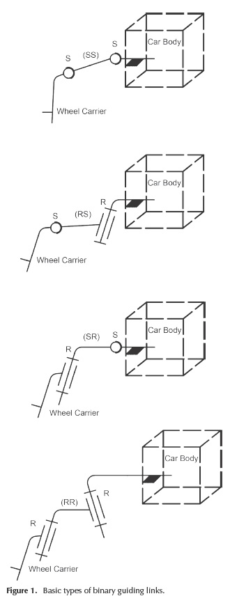
The wheel suspension system has an important role for the dynamic behavior of vehicles (Martinod et al., 2012). Unlike the classical dependent suspension design, in which the rear wheels are connected by a single beam / axle, most of the cars nowadays use independent suspension for the rear wheels (non-steered), in a similar way to the front wheels. The rear wheel suspension mechanisms consist of a number of links, with connections to the wheel carrier and the car body. The commonly used solution for connecting the guiding links to the adjacent elements is materialized by bushings or spherical plain bearings, which can be assimilated with ball (spherical) joints. For a guiding link with double-connection to wheel carrier or car body, the two ball joints determine in fact a revolute joint. Considering the two types of connections (spherical - S, and revolute - R), the following guiding solutions are obtained (Figure 1): the guidance on sphere of a point (SS) or axis (SR) belonging to the wheel carrier; and the guidance on circle (RS or RR, in a similar way to the previous case). Combining these, various configurations of wheel suspension mechanisms (with M=1 degree of mobility, corresponding to the vertical / up-down travel of the wheel) can be achieved.
The kinematic analysis and optimization of the suspension mechanisms is a permanent concern and challenge. The references pointed here give a relevant image of these developments.
Attia (2003) approached the kinematics of a five-point suspension mechanism in terms of the rectangular Cartesian coordinates of some defined points in the links and at the joints. Geometric constraints were introduced to fix the relative positions between the points belonging to the same rigid body.
Knapczyk and Maniowski (2003) proposed a method for the dimensional synthesis of a 5-rod wheel suspension mechanism on the basis of the geometric configuration of the mechanism, aiming to achieve the desired suspension characteristics.
A multi-body elastokinematic model of a car rear axle composed of two 5-rod suspensions with the suspension sub-frame was developed by Knapczyk and Maniowski (2006). A complex elastokinematic model was also developed for the multi-criteria optimization of a 5-rod car suspension in terms of car active safety and ride comfort (Knapczyk and Maniowski, 2010).
The method developed by Hiller and Woernle (1985) uses the modeling of the general spatial motion of the wheel as a screw motion, using the rotation indicators and tensors.
The algorithm developed by Raghavan (2004) for synthesizing the attachment point locations of the tie-rod is based on the computation of the center and normal of a circle by giving the coordinates of three points on the circle.
Rocca and Russo (2002) developed an algorithm for the kinematics of a multi-link mechanism with compliant joints, based on the solution of a typical non-linear least-squares problem.
Sancibrian et al. (2010) approached the kinematic design of double-wishbone suspension systems by a multi-objective dimensional synthesis based on gradient determination.
Both the kinematic analysis and synthesis of a five-link rear suspension mechanism were approached by Simionescu and Beale (2001), based on a fictitious mechanism that has all the links dismounted from their joints.
Zhao et al. (2009) approached the synthesis of an independent suspension that can guide the wheel to track a straight line when moving up and down by synthesizing a rigid body guidance mechanism and verifying the result through the screw theory.
The kinematic optimization of the suspension mechanisms can be also approached by design sensibility analyses, using as independent variables the coordinates of the joints (Balike et al., 2008).
A coupled kineto-dynamic analysis and optimization method was proposed by Balike (2010) for synthesis of vehicle suspension systems, based on quarter-car and two-dimensional roll plane models, with the aim of evaluating the significance of coupling the kinematic and dynamic responses for suspension synthesis.
On the other hand, specific optimization algorithms are integrated in the commercial Multi-Body Systems software environments (Ceccarelli, 2009), such as MSC.ADAMS. Generally, these methods are limited to mono-objective optimization problems, with or without design constraints (Alexandru, 2012).
This work deals with a novel analytical algorithm for the kinematic optimization of the rear wheels suspension mechanisms. The main purpose was to develop a kinematic optimization method that meets the following requirements: multi-criteria optimal design, meaning to improve at the same time more objective functions that describe the kinematic behavior of the car suspension mechanisms (in terms of minimizing their variations, with important benefits on the vehicle performance - stability, wear); generality (for the method to be applicable to all the rear wheels suspension mechanisms, obtained by combining the basic types of guidance shown in Figure 1, as well as for particular versions derived from those); unitary approach (for the optimization process to be conducted in the same way for all the rear wheels suspension mechanisms, without changes in the numerical algorithm and program); for the initial solution to be easily selected and accurate, thus assuring the fast convergence of the non-linear systems (with important benefits on the processing time).
Optimal synthesis algorithm
In kinematics, the wheel suspension mechanism is defined by the following parameters (Figure 2): the global coordinates of the joints on the car body, in OXYZ global reference frame (attached to the car body) - XM0i, YM0i, ZM0i, i = 1..n; the local coordinates of the joints on the wheel carrier, in PXpYpZp local reference frame - XMi(P), YMi(p), ZMi(P); the guiding arms lengths - li = |MM0i|; the initial position of the wheel, in OXYZ - Xp0, Yp0, Zp0; and the wheel radius - r.
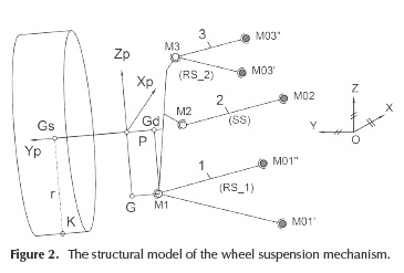
The global reference frame, which is attached to the car body, has the axes parallel with the longitudinal (X), transversal (Y) and vertical (Z) axes of the vehicle. The wheel reference frame has the origin P in the centre of the wheel axis. In accordance with the proposed method, the spatial position and orientation of the wheel (wheel carrier) in OXYZ, is defined by three specific points, as follows: the centre Gs of the wheel, and the projections Gd and G of the lower ball joint (M1) on the transversal (Yp ) and vertical (Zp ) axes of the wheel carrier reference frame.
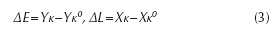
Relative to the car body (chassis), the wheels must have the possibility of vertical displacement. When the car is in motion, the modification of the suspension mechanism position determines (besides the necessary vertical motion) undesirable motions, such as: displacements of the wheel centre along transversal (ΔE) and longitudinal (ΔL) directions; modifications of the wheel axis orientation - toe angle (Δδ) and camber angle (Δγ) variations. The minimization of the undesirable motions can be transposed into kinematical optimization criteria: ΔE → 0, ΔL → 0, Δδ → 0, Δγ→ 0. These criteria cannot be equally satisfied, and for this reason a certain criterion has priority, or a compromise can be accepted, as follows: ΔEε [ΔE min, ΔEmax], ΔLε [ΔLmin, ΔLmax], Δδε[Δδmin, Δδmax], Δγ ε[Δγmin, Δγmax].
Note: The sixth motion of the wheel (i.e. the rotation around the transversal axis) is insignificant (negligible) due to the arrangement mode of the suspension mechanisms, close to the vertical - transversal plane. This variation is really important for the suspension mechanisms of the rear (beam) axle, as shown by Alexandru (2009). However, if the minimization of this rotation is necessary, the synthesis algorithm will not be affected, meaning only a supplementary condition when the wheel trajectory is imposed (see the paragraphs relating to Equation (7)).
The orientation angles of the wheel axis. The kinematic functions of the wheel suspension mechanisms ar e defined in relation to the global coordinates of the specific points (Figure 2 and 3), as follows:
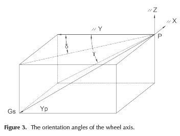
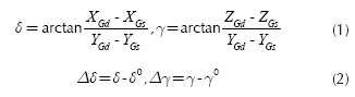
- The orientation angles of the wheel axis (toe angle -δ, camber angle - γ) and their variations (where "0" corresponds to the initial position of the suspension mechanism):
- The transversal and longitudinal displacements of the wheel (wheel track variation - ΔE, wheelbase - ΔL):
where the global coordinates of the contact point K result from the intersection between the vertical plane that contains the wheel axis and passes through Gs, normal on the wheel axis, the sphere that has the centre in Gs, and the radius r = Gs K.
Note: In road vehicles, the wheel track is the distance between the centreline of two wheels on the same axle, while the wheelbase is the distance between the centres of the front and rear wheels. In our case, the two measures are adapted to one wheel, being equivalent with the transversal (ΔY) and longitudinal (ΔX) displacements of the wheel.
By the proposed method, the local coordinates of the guiding points (i.e. the joints on the wheel carrier), and the initial position of the wheel are established by constructive criteria. Therefore, only the global coordinates of the points/joints on the car body remain available for the optimal synthesis of the wheel suspension mechanisms (in other words, the geometry of the wheel carrier will not be affected by the optimization process).
The proposed method contains three specific steps: imposing finite positions (trajectory) for the wheel carrier, determining the coordinates of the joints on the car body, and analyzing the suspension mechanism (obtained through the kinematic synthesis).
Between the nine global coordinates of the specific points, there are three relationships (in terms of constant distances),
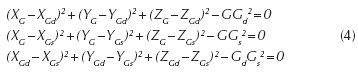
For any coordinates set for the specific points, which define the origin and the orientation of the wheel reference frame in relation to the global reference frame, the global coordinates of the guiding points Mi on the wheel carrier can be established as follows:
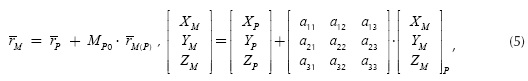
where rP is the position vector of the wheel carrier frame origin in the global reference frame, rM(P) - the position vector of the guiding point in the wheel carrier reference frame, and Mp0 - the matrix that defines the orientation of the wheel carrier reference frame relative to the global reference frame.
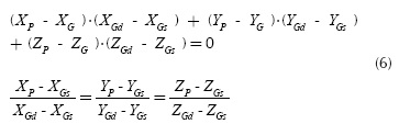
The coordinates of the origin P of the wheel carrier reference frame can be determined by the intersection between the wheel axis GsGd with the plane passing through G and normal to GsGd:
The finite positions that will be imposed to the wheel (i.e. to the specific points) can be established in accordance with the behavior of a concrete/real mechanism (vehicle). A viable way for imposing the kinematic behavior is based on the condition that on the desired/imposed trajectory of the wheel carrier, the final variations (after optimization) [ΔE, ΔL, Δδ, Δγ]f to be proportionally reduced relative to the initial values (before optimization) [ΔE, ΔL, Δδ, Δγ]1 are as follows:
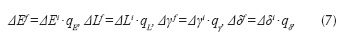
where qE, qL, qy and qδ are sub-unitary scale coefficients, which can be established on constructive criteria (to maintain the wheel suspension mechanism within rational constructive limits). If the solution obtained after the optimization (in terms of global coordinates of the joints locations on the car body) is inadequate from a technical point of view (for example, it does not fit into the chassis configuration), the optimization sequence must be repeated with other values of the sub-unitary scale coefficients.
Equation (4) and (7), along with the imposed vertical position of the wheel centre ZGs (the independent kinematic parameter), form the system that is used to determine the positions of the specific points on the chosen trajectory (see also the note from the top of the page). Then, the global coordinates of the guiding points Mi can be determined with Equation (5) and (6).
The guiding points Mi are constrained to remain on the fixed surfaces/curves having the centers M0i on the car body. For the guidance on sphere, the constraint equation has the form:
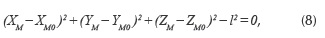
where the global coordinates of the point M were determined in the previous stage. The equation can be rewritten as follows:
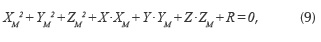
where:
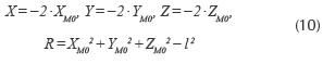
Writing Equation (9) for "m" positions, and subtracting the first relation (k = 1) from the others (k = 2,..., m), a system is obtained with "m - 1" equations and three unknowns (X, Y, Z).
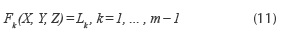
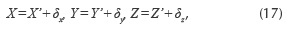
For m > 4 positions, an over-determined system is obtained, the solution being obtained with the least squares approach. Considering X', Y', Z', the solution for k = 1, 2 and 3, and subtracting from (11), the following equation is obtained:
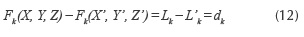
Considering that the differences δ =X-X', δ =Y-Y', δz = Z - Z' are small, the system (12) has the form:
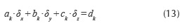
In accordance with the least squares approach, the solution of this system has to verify the equations:
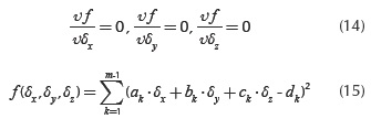
In this way, a linear system of 3 equations with 3 unknown factors (δx, δy, δz) is obtained:
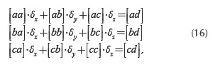
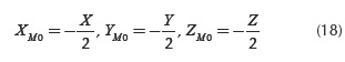
whose best solution can be expressed in the following form:
resulting in the global coordinates of the point of interest M0:
For the guidance on circle, meaning a link with two spherical joints (M0", M0") on the car body (similar to the lower and upper arms in Figure 2), the geometrical locus of the point M from the wheel carrier is a circle r (Figure 4), which can be determined by intersecting the sphere S (modeled by Equation (8)), with the plane π:
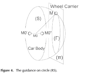
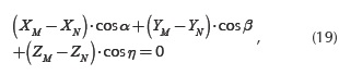
where N is a point in this plane, and cos α, cos β, cos η are the director cosines of the normal axis to the plane (the revolute axis).
Equation (19) can be rewritten in the following way:
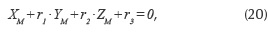
where r1, r2 and r3 are given by
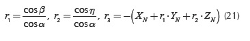
For "m" finite positions, by subtracting the first position, the following system is obtained (for k = 1, ... , m - 1):
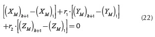
The global coordinates of the point M0 on the car body are established from Equation (8), while the direction of the revolute joint (in fact, the global coordinates for M0' or M0") is obtained from Equation (22), which is similar, as a solving way, to Equation (11).
Considering the algorithm for the basic guidance types, the optimal kinematic design can be performed in a similar way for all the rear wheel suspension mechanisms.
The kinematic analysis algorithm
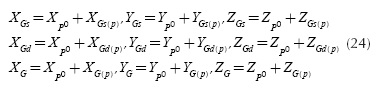
The method developed for the kinematic analysis is based on the same premise as in optimization: three specific points define the spatial position and orientation of the wheel. This assures an easy integration of the analysis algorithm into the general synthesis process. To determine the wheel position and orientation, we actually get to know the coordinates of the three specific points that define the wheel carrier reference frame with relation to the global reference frame. The specific points have the known local coordinates Gs (0,YGs(P), 0), Gd (0, YGd(P), 0), G (0, 0, ZG(P)), while the global coordinates Gs (XGs ,YGs , ZGs ), Gd (XGd,YGd, ZGd), Gd(XG, YG, ZG) will be determined through the kinematic analysis.
Establishing the global position of the wheel carrier involves the determination of the nine global coordinates of the specific points. There are three relationships (constant distances) between these points (see Equation (4)). In addition, there is a kinematic constraint equation which controls the vertical position ZGs of the wheel center. Therefore, five more equations are necessary to completely define the position and orientation of the wheel. These are obtained by imposing constraints to the guiding points, in relation with the guidance type (shown in Figure 1). For example, there are the following constraint equations for the three-link suspension mechanism (2 - RS and 1- SS) shown in Figure 2:
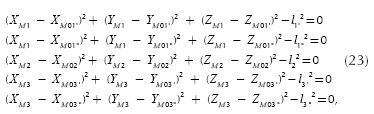
the global coordinates of the joints on the car body M0i being obtained in the synthesis algorithm (see the previous section).
Coupling the relationships - in terms of constant distances between the three specific points (Equation (4)), and the constraint equations of the guiding points (Equation (23)) -in correlation with the guidance type, non-linear equations systems are obtained. The unknowns of the kinematic analysis problem are represented by the global coordinates of the specific points Gs, Gd and G. In Equation (4), the unknowns are explicit, while in the constraint equations (Equation (23)) they appear as being implicit through the global coordinates of the guiding points Mi. The connection between the guiding points and the three specific points is given by Equation (5) and (6).
The Newton-Kantorovich approach is used for solving the non-linear system, in the following sequence (steps):
- Establishing the initial solution of the non-linear system, corresponding to the stationary position of the car (in rest):
- Determining the global coordinates of the wheel carrier frame origin, and the global coordinates of the guiding points (Equation (5) and Equation (6)), corresponding to the initial position of the mechanism.
- Establishing the Jacobian of the system, which is formed by the analytical partial derivatives of the equations Fi, i = 1...8 (where F1 - F3 are the rigid body conditions (Equation (4)), while F4 - F8 define the geometric constraints equations (Equation (23)) relative to the unknown global coordinates of the specific points Xi (XG, YG, YGs, XGd, YGd, ZGd). The global coordinate ZGs is the independent kinematic parameter, which controls the wheel travel.
- Establishing the new solution by using the Gauss approach.
- Comparing the new solution [Xi] with the initial one [Xi]0, in absolute value (e being the acceptable error):
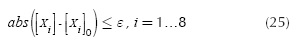
If the expression is satisfied, the new solution will be the final solution of the system. Otherwise, the iterative process is repeated from the step 'b', considering as initial solution in the current iteration the values from the previous one.
The iterative process "a → d" is finished when the differences between values in two successive iterations ("m" and "m - 1") satisfy the imposed precision (in a similar way as with Equation (25)), the final solution being {XG, YG, ZG, XGs, YGs, XGd, YGd, ZGd}m.
For a current position of the mechanism (ΔZGs#0), the initial solution of the system corresponds to the previous position, and in this way the kinematics of the suspension mechanism is established for the whole travel (up - down) of the wheel. Finally, Equations (1-3) are used to determine the kinematic functions.
Case study
Based on the algorithm described above, a computer program for the kinematic analysis and optimization of the rear wheel suspension mechanisms was developed in C++. The application is carried out for a three-link suspension mechanism (2-RS and 1-SS), whose structural model is similar to that shown in Figure 2. The numerical data used in this study, meaning the global or local coordinates of the design points (as they are described in the second section, in correlation with the notations in Figure 2) in the initial (before optimization) rear wheel suspension mechanism, have been collected from the technical documentation (execution and assembly drawings) of the single-seater race car of the Transilvania University of Bra§ov. In the initial design, the global coordinates of the joints on chassis have the following values (in mm): M01, (-158,54, 303,69, -62,54), M01 (205,81, 307,71, -62,67), M02 (-146,39, 300,0, -40,14), M03' (-151,41, 316,19, 80,05), M03 (197,14, 320,51, 84,56). It should be mentioned that in the physical prototype, the connections of the guiding arms to the adjacent parts (chassis and wheel carrier) are made through spherical bearings.
The kinematic analysis was performed considering the wheel travel (down - up) in the value range ΔZGsε [-80, 80] mm relative to the initial position, the simulation step (between two iterations) being of 1 mm. It must be said that the method allows the use of a higher step (e.g. 5 or 10 mm), without affecting the convergence of the non-linear system.
To keep the mechanism within rational constructive limits, i.e. the joints on the car body fitting in a certain area, the following scale coefficients were used: qE=0,5, qL = 0,05, qγ= 0,3, qδ = 0,05. The values represent the best compromise between the functional and constructive requirements; in other words a smaller scale (i.e. higher reduction), mainly for the wheel track variation, would mean an escalation of the available constructive limits.
In this way, the imposed values of the interest parameters (ΔEf, ΔLf, Δδf, Δγf) have been obtained from the initial variations (ΔEi, ΔLi, Δδi, Δγ), for the whole motion range of the wheel. Then, for each position of the wheel, the set of values for the global coordinates of the specific points Cs, Cd and C are established with Equations (1-4), while Equation (5) and (6) are used for the global coordinates of the guiding points M1, M2, M3.
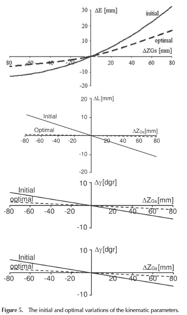
The optimization algorithm has been applied for each basic binary link (RS_1, RS_2, SS), obtaining in this way the optimal locations of the joints on the car body: M01' (-152,06, 281,69, -55,76), M0r(177,55, 282,01, -54,46), M02 (-179,40, 272,59, -41,13), M03' (-149,84, 287,74, 108,18), M03 (156,23, 289,0, 107,72). The comparative analysis of the initial (before optimization) and optimal results (Figure 5) shows that the suspension mechanism obtained by the proposed optimization method assures, largely, the imposed reduction of the initial variations, and this proves the usefulness (viability) of the proposed kinematic synthesis algorithm.
The so obtained suspension mechanism was manufactured and implemented in the rear wheels suspension system of the targeted race car (Figure 6). The wheel travel is transferred to the spring and damper assembly (which is disposed in horizontal plane) from the upper guiding arm (3) through a pusher and rocker group (4). The car was experimentally tested in accordance with the normative for its class. A more detailed discussion on the physical prototype as well the experimental testing will be subjects for a future work.

Conclusions
The method employed allows the multi-criteria optimization of the suspension mechanisms used for the rear wheels of the motor vehicles. For this study, four design objectives have been considered: the optimization aiming to minimize (as much as possible in terms of functional and constructive requirements) the wheel track, wheelbase, toe angle, and camber angle variations. The optimization process can be extended by considering more objectives (criteria), depending on the design requirements (e.g. caster angle, kingpin inclination).
The proposed method is characterized by generality and unitary approach. The general feature is assured by decomposing the suspension mechanism in elementary (basic) binary chains, which are separately studied. With these basic chains, there is the possibility of building any type of rear wheel suspension mechanism. In the mechanism context, the "connection" between the basic chains is assured by the global coordinates of the joints on the wheel carrier, whose spatial positions (trajectories) are imposed (so, these are input data in the synthesis algorithm). The method can also be applied for the multilink suspension mechanisms of the front wheels (including the McPherson suspension design), as well as for the suspension mechanisms of the rear beam axles.
The kinematic analysis algorithm is based on the same premise as the synthesis, allowing the integration of the synthesis and analysis sequences into a general design and simulation process. The initial solution of the non-linear system that models the mechanism can be accurately determined, and this assures a fast convergence, with various iteration steps (this is important for reducing the processing time by computer). The computer program allows a comparative study of different types of wheel suspension mechanisms, with particular values of the input data. The kinematic analysis algorithm can be integrated into a more complex virtual mechanical work-based method for determining the equilibrium position of the wheel guiding mechanism relative to chassis, considering the external forces applied to the wheels, as well as the reaction forces in the elastic elements of the suspension. It is intended to present this in a future work.
References
Alexandru, C. (2009). The kinematic optimization of the multi-link suspension mechanism used for rear axle of the motor vehicle. Proceedings of the Romanian Academy, 10(3), 244-253. [ Links ]
Alexandru, C. (2012). Optimal design of the mechanical systems using parametric technique and MBS (Multi-Body Systems) software. Advanced Materials Research, 463-464, 1129-1 132. DOI: www.scientific.net/AMR.463-464.1129. [ Links ]
Attia, H.A. (2003). Kinematic analysis of the multi-link five-point suspension system in point coordinates. Journal of Mechanical Science and Technology, 17(8), 1133-1139. [ Links ]
Balike, K.P., Rakheja, S., & Stiharu, I. (2008, August). Kinematic analysis and parameter sensitivity to hard points of five-link rear suspension mechanism of passenger car. Paper presented at Design Engineering Technical Conference, New York, 755-764. [ Links ]
Balike, K.P. (2010). Kineto-dynamic analyses of vehicle suspension for optimal synthesis. Doct. Thesis, Concordia University, Montreal. [ Links ]
Ceccarelli, M. (2009, October). Challenges for mechanism design. Paper presented at 10th IFToMM International Symposium on Science of Mechanisms and Machines SYROM, Bra§ov, 1-13. [ Links ]
Hiller, M., & Woernle, C. (1985). Kinematical analysis of a five-point wheel suspension. ATZ, 87(2), 59-64. [ Links ]
Knapczyk, J., & Maniowski M. (2003). Dimensional synthesis of a five-rod guiding mechanism for car front wheels. The Archive of Mechanical Engineering, 50(1), 89-116. [ Links ]
Knapczyk, J., & Maniowski, M. (2006). Elastokinematic modeling and study of five-rod suspension with subframe. Mechanism and Machine Theory, 41(9), 1031-1047. DOI: 10.1016/j.mechmachtheory.2005.1 1.003. [ Links ]
Knapczyk, J., & Maniowski M. (2010). Optimization of 5-rod car suspension for elastokinematic and dynamic characteristics. The Archive of Mechanical Engineering, 52(2), 133147. DOI: 10.2478/v10180-010-0007-x. [ Links ]
Martinod, R.M., Betancur, C.R., & Castañeda, L.F. (2012). Evaluating damping elements for twostage suspension vehicles. Ingenieria e Investigacion, 32(1), 11-17. [ Links ]
Raghavan, M. (2004). Suspension design for linear toe curves: a case study in mechanism synthesis. Journal of Mechanical Design, 126(2), 278-282. DOI: 10.1 1 15/1.1667933. [ Links ]
Rocca, E., & Russo, R. (2002). A feasibility study on elasto-kinematic parameter identification for a multilink suspension. Journal of Automobile Engineering, 216(2), 153-160. DOI: 10.1243/0954407021528995. [ Links ]
Sancibrian, R., Carcia, P., Viadero, F., Fernandez, A., & DeJuan, A. (2010). Kinematic design of double-wishbone suspension systems using a multiobjective optimisation approach. Vehicle System Dynamics, 48, 793-813. DOI: 10.1080/00423110903156574. [ Links ]
Simionescu, P.A., & Beale, D. (2002). Synthesis and analysis of the five-link rear suspension system used in automobile. Mechanism and Machine Theory, 37(9), 815-832. DOI: 10.1016/S0094-114X(02)00037-X. [ Links ]
Zhao, J.S., Chu, F., Feng, Z. J., & Zhao, S. (2009). Synthesis of a rear wheel suspension mechanism with pure rectilinear motion. Journal of Mechanical Design, 131(10), 71- 79. DOI: 10.1115/1.3179153. [ Links ]

