


Servicios Personalizados
Revista
Articulo
 Inglés (pdf)
 Articulo en XML
 Referencias del artículo
 Enviar articulo por email
Indicadores
-
 Citado por SciELO
 -
 Accesos
Links relacionados
-
 Citado por Google
 -
 Similares en
SciELO
Similares en
SciELO -
 Similares en Google
Compartir

 Permalink
Ingeniería e Investigación
versión impresa ISSN 0120-5609
Ing. Investig. vol.36 no.3 Bogotá sep./dic. 2016
https://doi.org/10.15446/ing.investig.v36n3.53792
DOI: http://dx.doi.org/10.15446/ing.investig.v36n3.53792
Design of a 200 kW electric powertrain for a high performance electric vehicle
Diseño de un tren de potencia eléctrico de 200 kW para un vehículo eléctrico de alto desempeño
Wilmar Martinez1, Camilo A. Cortes2, Luis E. Munoz3, and Masayoshi Yamamoto4
1 Electronics Engineer, M.Sc., Ph.D. Shimane University, Japan. Affiliation: Postdoc, Toyota Technological Institute, Japan. E-mail: whmartinezm@unal.edu.co
2 Electrical Engineer, Ph.D. Universidad Nacional de San Juan, Argentina. Affiliation, Associate Professor, Universidad Nacional de Colombia, Colombia. E-mail: caacortesgu@unal.edu.co
3 Mechanical Engineer, M.Sc., Ph.D. Politecnico di Milano, Italy. Affiliation: Associate Professor, Universidad de Los Andes, Colombia. E-mail: lui-muno@uniandes.edu.co
4 Electronics Engineer, M.Sc. Ph.D. Yamaguchi University, Japan. Affiliation: Associate Professor, Shimane University, Japan. E-mail: yamamoto@ecs.shimane-u.ac.jp
How to cite: Martínez, W., Cortes, C. A., Munoz, L. E., & Yamamoto, M. (2016). Design of a 200 kW electric powertrain for a high performance electric vehicle. Ingeniería e Investigación, 36(3), 66-73. DOI: 10.15446/ing.investig.v36n3.53792
ABSTRACT
With the purpose of designing the electric powertrain of a high performance electric vehicle capable of running a quarter mile in 10 seconds, firstly it is necessary to calculate the required energy, torque, and power in order to size and select the suitable storage components and electric motors. Secondly, an assessment of the powertrain arrangement is needed to choose the best internal configuration of the vehicle and guarantee the highest efficiency possible. Finally, a design of the power conversion stages, specifically the DC-DC converter that interfaces the storage unit with the electric motors, is required as well. This paper shows the energy calculation procedure based on a longitudinal dynamic model of the vehicle and the selection method of the storage components and motors needed for this application, as well as the design of two 100 kW interleaved boost converters with coupled inductors. In addition, a novel operation of the interleaved boost converter is proposed in order to increase the efficiency of the converter. As a result, the designed converter achieved a power density of 24,2 kW/kg with an efficiency of 98 %, which was validated by experimental tests of a low power prototype.
Keywords: Electric vehicle, ultracapacitors, interleaved dc-dc converter, coupled inductor, efficiency, power density.
RESUMEN
Para diseñar el tren de potencia de un vehículo eléctrico de alto desempeño capaz de correr un cuarto de milla en 10 segundos, primero es necesario calcular la potencia y energia necesarias para dimensionar y seleccionar los componentes de almacenamiento y los motores adecuados. Segundo, se requiere una evaluación de varios trenes de potencia para seleccionar la mejor configuración interna del vehículo con el propósito de garantizar la mayor eficiencia posible. Finalmente, se necesita un diseño del convertidor de potencia DC-DC que haga la interfaz entre la unidad de almacenamiento y los motores eléctricos con sus respectivos inversores. Este artículo presenta el procedimiento para el cálculo de la energia necesaria para correr el vehículo con base en un modelo dinámico longitudinal. Así mismo, se presenta el método de selección de los componentes de almacenamiento de energía necesarios. Finalmente, se presenta el diseño de dos convertidores intercalados con inductores acoplados de 100 kW operando bajo una novedosa operación propuesta para incrementar la eficiencia del convertidor. Como resultado, el convertidor diseñado logró una densidad de potencia de 24,2 kW/kg y una eficiencia de 98 %, la cual es validada con pruebas experimentales de un prototipo de baja potencia.
Palabras clave: Vehículo eléctrico, supercondensadores, convertidor dc-dc intercalado, inductor acoplado, eficiencia, densidad de potencia.
Received: October 26th 2015 Accepted: November 18th 2016
Introduction
Electric Vehicles (EVs) are an emerging technology with a growing interest because they can contribute to the solution of some of the sustainability issues of transportation. This is possible because EVs have been improved to reduce energy consumption and greenhouse gas emissions. Therefore, EVs offer outstanding advantages of, inter alia, high efficiency, digital controllability and regenerative braking (Gu et al., 2013; Yilmaz et al., 2013). However, current autonomous EVs often present limited autonomy in comparison to Internal Combustion Engine (ICE) vehicles. The main reason for this limitation is the reduced energy capacity of modern storage technology devices (Aharon et al., 2011; Martinez et al., 2012a).
With the purpose of studying and promoting the use of this technology in an efficient way, Universidad Nacional de Colombia, Universidad de Los Andes and Shimane University have been working together on a project aimed at designing and constructing a high performance EV capable of running a quarter mile in 10 seconds or less. Therefore, the first design parameter is the All Electric Range (AER) defined as 402,3 m. The development of this vehicle has two purposes: 1) to provide a demonstrative platform of the EV capabilities on a scenario in which the energy constraints are relaxed; given the fact that the power requirements for the demonstrative platform are similar to the power requirements of a commercial electric bus (Mantilla et al.,2008) ; and 2) to contribute to the development of electric powertrain components for commercial EVs.
This design starts with the calculation of the stored energy, torque, and power needed to reach the goal in the proposed time. Therefore, it is necessary to establish a longitudinal dynamics model where the forces involved in the vehicle motion are considered. The energy storage unit and the power management unit are critical to the autonomy of the vehicle because motors require a large amount of power to generate the required speed and torque (Bonfligio et al., 2009) . For these reasons, the selection of high efficiency density / high power density storage devices and high torque / high efficiency electric motors are required. In addition, the design of the DC-DC converter that interfaces the motors with the storage devices is needed as well.
The energy storage system required in the particular case of this high performance EV is different from the storage systems used in conventional applications because of two main reasons: 1) it requires a smaller amount of stored energy in comparison with a commercial vehicle due to the short race distance; and 2) it requires a considerable amount of power associated with the race conditions. Consequently, high power density storage technologies are essential for fulfilling the race requirements.
This study is organized as follows: First, the calculation of the power, energy, and torque required to reach the 10 seconds goal is performed based on a longitudinal model of the vehicle. Second, the energy storage elements are selected using a novel sizing methodology. Third, an efficiency evaluation of different powertrain arrangements is conducted. Fourth, the design of a high power density and highly efficient DC-DC converter operating under a novel concept is shown. Finally, the experimental validation of the DC-DC converter design is presented with the test of a 100 W prototype.
Power, energy, and torque
The first step of this design is the definition of a geometrical layout of the entire vehicle in order to derive a longitudinal dynamics modeling of the forces that have interaction in the vehicle. Then, a computational processing of this model is conducted considering several initial requirements. Finally, an approximation of the needed power, energy, and torque is obtained from a simulation run in Matlab.
Longitudinal dynamics model
The longitudinal dynamics model is obtained by the motion equation of the vehicle. It defines the change in the longitudinal motion of the vehicle caused by the net longitudinal force applied on it (Munoz et al., 2012). This net force is obtained by using both tractive and resistive forces acting on the vehicle. The free body diagram associated to this model, with the forces that interact in the vehicles, is presented in Figure 1.
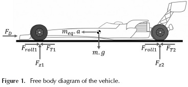
The equation of motion is obtained as follows:

where FT is the total tractive force; FG is the longitudinal component of the gravitational force; Froll is the total rolling resistance force; FD is the aerodynamic drag force; meq is the equivalent mass; and a is the longitudinal acceleration. Consequently, when the tire slip is excluded from the analysis, the tractive force on the i-th wheel can be expressed as:
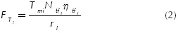
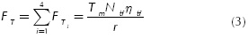
where Tmi is the instantaneous i-th motor torque, which is a function of the state of the motor represented by its angular speed; Ntfi is the i-th total reduction ratio from the motor to the wheels; ntfi is the i-th transmission efficiency; and ri is the i-th wheel's dynamic radius. Moreover, the total tractive force is represented by the sum of the tractive force of all four wheels. For the prototype under development, the total reduction ratio, the transmission efficiency, and the dynamic radius of each wheel are the same, and are represented as Ntfi,ηti r, and respectively. If Tm is defined as the sum of all motor torques, the total tractive force can be derived as follows:
In this case, the racing track has practically a zero-degrees condition for the whole trajectory. Hence, the longitudinal component of the gravitational force is not considered here (Rosario et al., 2006). The rolling resistance force is produced by the hysteresis of the contact between the tires and the road surface. The total rolling resistance force is the sum of the rolling resistance forces of all tires, and it can be modeled as:
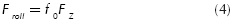
where fo is the rolling coefficient and Fz is the vehicle total vertical force of interaction with the ground. In addition, the aerodynamic drag force is produced by the viscous and pressure effects of the surrounding air that interacts with the vehicle's surface (Castro et al., 2013; Hucho, 1998). When the wind speed is out of consideration, this force can be represented as:
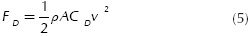
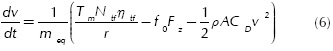
where p is the air density; A is the vehicle equivalent frontal area; CD is the aerodynamic drag coefficient; and v is the vehicle longitudinal speed. Finally, the product meqa is the inertial effect originated by the net force acting on the vehicle. The equivalent mass meq comprises the net mass of the vehicle plus the effective mass of the rotating components (Gillespie, 2013). From Equations (1),(3)-(5), it is possible to derive the longitudinal dynamics model in terms of the speed change during the time of the race:
Mechanical parameters
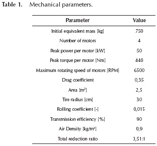
The mechanical parameters were defined based on a geometrical layout obtained after several design iterations considering the mechanical and electrical points of view. The parameters of the pre-selected motors were also taken into account. In the first scenario, the longitudinal dynamics model, shown in Equation (6), is solved and used to estimate the mechanical energy consumption (Gillespie, 2013). The mechanical parameters of the proposed scenario are presented in Table 1. In this case, it is assumed that the tires would have a traction coefficient sufficiently high to transfer the forces to the road with an average longitudinal slip of less than 5 % and a whole transmission efficiency of ntf = 0,9. Finally, this vehicle is designed to run in the outskirts of Bogota, Colombia, where the air density is approximately p = 0,9 kg/m3.
The model shown in Equation (6) is a nonlinear differential equation that is numerically solved using the parameters defined in Table 1. As a matter of fact, in an early stage of the project, this model was parametrically used with the purpose of selecting the total reduction ratio that minimizes the total race time. When the parameters are selected, the model is used for the prediction of the kinematics and kinetics behavior of the vehicle. The main kinematics result obtained from this model is the speed profile of the vehicle as a function of time for the duration of the entire race (see Figure 2a). Here, the maximum speed obtained during the race is 211 km/h. The kinetics results obtained from this model include the evolution of the total torque and power of the motors across the time, which are presented in Figure 2b. After 0,4 seconds the power reaches its maximum value of 200 kW. Finally, the computation of the mechanical energy needed to run the quarter mile under the given conditions is calculated. This computation is performed by integrating the power across the time as shown in Equation (7) (Luk et al., 2006). Thus, the mechanical energy estimated for the race is 531 Wh.
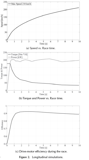
In this context, the energy conversion efficiency of the motors is considered as well. Based on the mechanical power estimation shown in Figure 2b, combined with the motor efficiency performance shown in Figure 2c, it is possible to estimate the electric energy needed to run the vehicle. As a result, it is found that the required electric energy is 595 Wh.
Based on these calculations and the model evaluation, it is possible to select the suitable storage devices and electrical motors.
Storage and motor selection
Storage
A suitable energy storage technology should fulfill several requirements: 1) high energy density to store the 595 Wh in the smallest package possible; 2) high power density to transfer 200 kW of power instantaneously; and 3) light and compact package to avoid extra mass and volume, which demands additional stored energy. In this perspective, batteries or similar systems (e.g. fuel cells) with high specific energy are considered as adequate devices to store the needed energy. In the same way, capacitors and ultracapacitors are evaluated due to their high specific power.
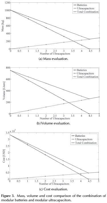
Considering the power, torque, and energy requirements described in the previous section, a novel storage sizing methodology is employed to determine the optimal storage component. As a result, a combination of modular batteries and modular ultracapacitors has proved to be the most proper option to store the required energy (Martinez et al., 2012a). Therefore, Figure 3 shows the mass, volume and cost comparison of the combination of modular batteries and modular ultracapacitors needed to store the 595 Wh and to deliver it in 10 seconds at 200 kW of power. Figure 3 shows the number of batteries ( ), ultracapacitors (
 ) and the combination of these devices (
 ). Additionally, the intersection of the and lines corresponds to the case where batteries and ultracapacitors contribute with half the mass, volume, or cost of the total combination system. Furthermore, all combinations present a negative slope when the number of ultracapacitors is increased. This scenario is obtained due to the high power density characteristic of ultracapacitors, which is quite convenient for the race objective. In addition, ultracapacitors offer a major advantage in terms of shelf life because they can offer about one million cycles in comparison to the 30.000 cycles offered by some of the outstanding batteries in the market. In the long term, the reduced shelf life of batteries affects the cost evaluation because of the replacement cost.
In conclusion, ultracapacitors are a suitable storage element in this high performance application because they can provide a large amount of power in a short period of time and they offer a longer shelf life. In consequence, a Nesscap 62 F/125V ultracapacitor was selected because it is a high voltage modular ultracapacitor capable of storing 134,5 Wh and delivering its energy at a peak current of 1850 A. This module has 58,3 liters of volume and 57 kg of mass. In this context, a minimum of five modules is needed to supply the required energy.
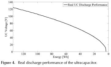
Furthermore, a charge and discharge test of the 125V ultracapacitor module was conducted in order to characterize the device and to obtain the discharge performance, which is the basis of the DC-DC converter design. Figure 4 shows the experimental 125 V ultracapacitor discharge profile.
Motors
As Figure 2b shows, the vehicle must have a propulsion machine capable of delivering 200 kW and 1540 Nm. Consequently, after a selection process where the power density was the main characteristic taken into account, four UQM 50 kW Brushless Permanent Magnet (BLPM) motors were chosen. Each motor includes a three-phase inverter. It was decided to use four motors instead of one because: 1) a considerable mass reduction is achieved, as there is no mechanical transmission; and 2) the speed and torque control is faster because an independent electronic control focused in each motor without mechanical transmission can be used. Additionally, the BLPM technology was chosen due to its power density characteristic, which is higher than the one of other conventional motor technologies. Each motor has a nominal voltage of 300-430V; a current limitation of 400 A; a peak torque of 440 Nm; and a maximum speed of 6500 rpm.
Powertrain configuration
Finally, having selected the energy storage elements and the motors, the next step is the design of the optimal powertrain configuration in the vehicle to obtain the highest efficiency possible. Martinez et al. (2012b) explains in detail a power loss analysis of the possible powertrain configurations in the vehicle based on a first approximation of the DC-DC converter. As a conclusion, it was decided to use six ultracapacitors instead of five in order to ensure a minimum voltage in the storage unit after the race. As Figure 4 shows, the ultracapacitor's voltage decreases as the energy is discharged. Therefore, a storage system with only five modules will only have a voltage of 26,2V at the end of the race, which produces high power losses due to the high input current and the extremely high voltage conversion ratio. Moreover, six modules are important in order to protect the DC-DC converter and ensure the race conditions. A very low voltage in the storage unit will require a tremendous high current that probably: 1) will damage the DC-DC converter, 2) the ultracapacitors cannot deliver, and 3) the full power cannot be achieved and the 10 seconds target will not be accomplished. Consequently, the total AER of the vehicle will be 815 m, supposing a full discharge of the six ultracapacitors which is not harmful for them.
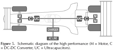
In this context, the powertrain configuration selected for this application is composed of a storage system divided in two parts. Each part has three ultracapacitors connected in series feeding a 100 kW DC-DC converter. Each DC-DC converter makes the interface between the three ultracapacitors and the inverters of the two BLPM motors (see Figure 5). Both parts of the system have an Energy Management System (EMS) capable of controlling the power flow in order to balance both parts of the powertrain to 100 kW.
At the beginning of the race, each part of the storage system has a rated voltage of 375V for feeding the pair of motors, whose operation requires minimum 300V. At the end of the race, when the 595 Wh are consumed, each part of the storage system will have a voltage of 170V as a result of the discharge of the ultracapacitors. As a consequence, a DC-DC converter with a voltage conversion ratio between 0,8 and 1,76 is required.
DC-DC converter
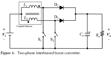
A conventional single-phase boost topology was considered and evaluated in Martinez et al. (2012b). However, the calculated values of the filter inductance and the output capacitance were 2,3 mH and 5,4 uF, respectively. An inductor of this value, with a wire capable of conducting 600 A, brings a large volume, mass, and cost to the system. In addition, single-phase boost converters present a high input current ripple that generates a rising temperature in the storage system and thereby high power losses and shelf-life reduction (Yu et al., 2014). As a consequence, it was necessary to study different DC-DC converter topologies that offer high efficiency, low current ripple, and small size. Under these conditions, multilevel and interleaved converters were studied and evaluated in detail in Martinez et al. (2013). As a result, an interleaved converter was selected due to its high current capability, low ripple current, and the ability of smoothing capacitor downsizing (Nai et al., 2012). Moreover, in order to increase the power density of the interleaved converter, a magnetic coupling technique was used to reduce the mass and volume of the inductive components. Finally, a two-phase interleaved boost converter with a coupled inductor (Figure 6) was selected to interface three ultracapacitors in parallel with two BLPM Motors and their inverters.
Converter's operation
The two-phase interleaved boost converter is composed of a magnetic coupled inductor made of two windings, usually installed in an EE or EI core. In these geometries, the windings are inversely coupled in order to suppress DC flux inductions. Each of the windings, L1 and L2, is wound with the same number of turns to ensure the symmetry between the phases. Additionally, this converter is made with two power switches, S1 and S2, which are alternatively commuted with a phase shift of 180 degrees, two diodes D1 and D2, and one output capacitor Co. The full operating principle is presented in Imaoka et al. (2011). This converter offers the advantage of input current splitting, which allows the use of components with smaller rated power and windings with a smaller sectional area. Using smaller cores and windings contributes to the downsizing of the inductor and thereby to increase the power density of the system. In addition, the magnetic coupling technique offers the advantage of input current reduction due to the effect of the mutual inductance M between each winding (Hirakawa et al., 2009). Finally, this converter operates at twice the frequency due to the interleaved technique and the phase shift between the switches. Therefore, a downsizing of the output capacitor is obtained (Imaoka et al., 2011).
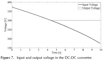
To design the 100 kW converter, it is necessary to establish several initial parameters and a converter model in order to select a suitable operation point which offers the highest efficiency possible. Taking into account the ultracapacitor discharge performance shown in Figure 4, and the converter requirements explained above, it is possible to infer the challenge of this EV due to the constant voltage drop of the storage unit, which demands a continuous modulation of the duty cycle in the converter. Consequently, a novel operating condition was implemented in this converter. This condition allows a freewheeling power transmission from the storage unit to the motors via the DC-DC converter when the voltage of the storage unit is higher than 300V. Thereafter, when the storage unit is discharged with a voltage level lower than 300 V, the interleaved boost converter starts its operation as shown in Figure 7. With this concept, it is possible to eliminate the switching losses during the first four seconds of the race.
Optimal switching frequency
With the purpose of obtaining the highest efficiency possible, an efficiency optimization methodology was applied, where the power loss model of Martinez et al. (2013) was implemented to find the optimal switching frequency that offers the lowest losses. This optimization procedure is based on an analytical algorithm that aims to compare the power losses of each component and select the best efficiency point where those losses can be minimized. In this context, considering the loss performance of each component, Figure 8a shows the total loss performance of the 100 kW converter neglecting the output capacitor losses. In this figure, the influence of switching losses, when the voltage of the storage unit is lower than 300V, is evident. In addition, the largest losses are presented in the lowest discharge point, i.e., at 170V. Figure 8b shows the total losses when the storage unit presents 170V. Large losses are produced at low frequencies because of the inductor copper losses, and extremely high losses are produced at high frequencies due to semiconductor switching losses and core losses.
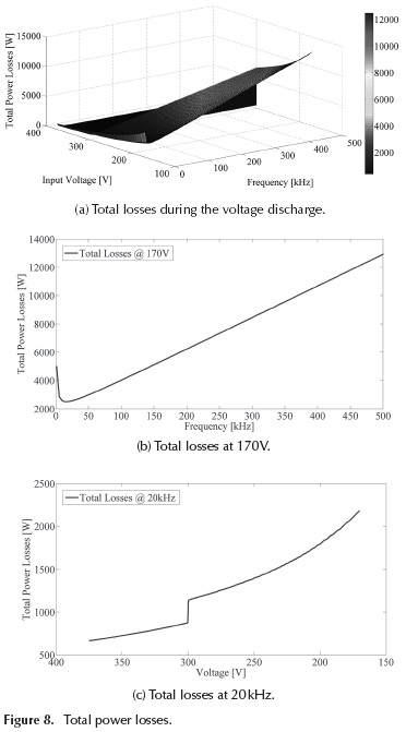
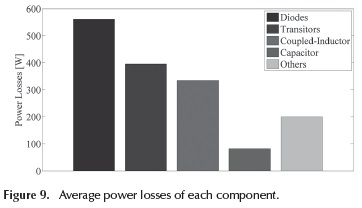
As a result, the optimal switching frequency obtained by the efficiency optimization methodology is 20 kHz, which is the point with the lowest power losses shown in Figure 8b. Finally, taking into account the IGBTs, the diodes, the magnetic core, and the windings selected for this study, and a post-selection of the input and output capacitor, the total power loss performance at the selected switching frequency of 20 kHz is shown in Figure 8c. This figure shows the power losses during the discharge process of the ultracapacitors. In this figure, the influence of the novel condition proposed in this study is recognizable because there is a sudden increase of 400W in the power losses when the DC-DC converter starts its switching operation. Finally, an average power loss per component was calculated and shown in Figure 9. Based on this analysis, the total average losses are close to 1873 W during the race time; consequently, the theoretical average converter efficiency is 98,1 %.
Furthermore, a calculation of the mass and volume of each component and the entire system, including an estimated casing, is presented in Martinez et al. (2013). As a result, a gravimetric power density of 24,2 kW/kg and a volumetric power density of 29,7 kW/liter were achieved.
Experimental validation
A 100 W prototype was constructed as a validation of the design; the efficiency of this prototype was measured at 12V of output voltage and a range of 15 to 7V of input voltage using a 15V ultracapacitor. Figure 10 shows the experimental setup of the 100 W prototype.
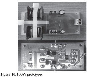
The purpose of this prototype is to validate by experiments the performance of the selected converter topology in a low power and voltage prototype. Despite the fact that a 100 W prototype is not an appropriate way to validate the operation of a 100 kW system, it is a suitable setup to validate the operating condition of free-wheeling and switching performance described above.
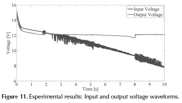
Summing up, the prototype operates at a conversion ratio M between 1 and 1,71. Figure 11 shows the input and output voltages, where it is possible to see the discharge performance and the constant output voltage. The experimental tests showed a low ripple current and a measured efficiency of 97,5 %. Consequently, the effectiveness of the proposed design and the presented condition are validated.
Conclusions
In this paper, firstly, the energy, power, and torque needed by a vehicle to run a quarter mile in 10 seconds were calculated based on a longitudinal dynamics analysis. Consequently, to reach the goal, the EV needs 595 Wh, 200 kW, and 1760 Nm. Secondly, the storage unit was selected based on a methodology for sizing ultracapacitors and batteries considering mass, volume, cost, and shelf life criteria. Consequently, 125V modular ultracapacitors were selected due to their high power density that is suitable for the race conditions. Then, the design of the DC-DC converter that interfaces the storage unit with the selected motors was performed. During this design, several topologies were studied, and a two-phase interleaved boost converter with a magnetic coupling inductor was selected. Afterward, an efficiency optimization methodology was implemented in order to calculate the suitable switching frequency. Thus, it was found that 20 kHz offers the lowest value of losses.
Finally, an efficiency of 98,1 % was estimated as a result of the novel operating condition proposed for this study. In addition, a gravimetric power density of 24,2 kW/ kg and a volumetric power density of 29,7 kW/liter were calculated as an evidence of the high power density of the 100 kW DC-DC converter for the high performance EV. As a validation of the proposed operating condition, a 100 W prototype was experimentally tested.
References
Aharon. I., & Kuperman, A. (2011). Topological Overview of Powertrains for Battery-Powered Vehicles with Range Extenders. IEEE Transactions on Power Electronics, 26(3), 867-870. DOI: 10.1109/TPEL.201 1.2107037. [ Links ]
Bonfiglio, C., & Roessler, W. (2009). A Cost Optimized Battery Management System with Active Cell Balancing for Lithium Ion Battery Stacks. Vehicle Power and Propulsion Conference, VPPC'09, 304-309. DOI: 10.1109/vppc.2009.5289837. [ Links ]
Castro, N., Lopez, O., & Munoz, L. (2013). Computational prediction of a vehicle aerodynamics using detached Eddy simulation. SAE International Journal of Passenger Cars -Mechanical Systems, 6(1), 414-423. DOI: 10.4271/2013-01-1254. [ Links ]
Donglai, G., Yu, Z., & Zhongyang, Z. (2014). Input Current Ripple Cancellation Technique for Boost Converter Using Tapped Inductor. IEEE Transactions on Industrial Electronics, 61(10), 5323-5333. DOI: 10.1109/TIE.2014.2300045. [ Links ]
Gillespie, T. (1992). Fundamentals of vehicle dynamics. 1st Ed., SAE International. DOI: 10.4271/r-114. [ Links ]
Gu, B., Lai, J., Kees, N., & Zheng, C. (2013). Hybrid-Switching Full-Bridge DC-DC Converter with Minimal Voltage Stress of Bridge Rectifier, Reduced Circulating Losses, and Filter Requirement for Electric Vehicle Battery Chargers. IEEE Transactions on Power Electronics, 28 (3), 1132-1144. DOI: 10.1109/TPEL.2012.2210565. [ Links ]
Hirakawa, M., Nagano, M., Watanabe, Y., Andoh, K., Nakatomi, S., & Hashino, S. (2009). High Power Density DC/DC Converter using the Close-Coupled Inductors. IEEE Energy Conversion Congress and Exposition, (ECCE), 1760-1767. DOI: 10.1109/ECCE.2009.5316389. [ Links ]
Hucho, W.H. (1998). Aerodynamic Drag of Passenger Cars. Aerodynamic of road vehicles. SAE International, Warendale, PA. [ Links ]
Imaoka, J., Ishikura, Y., Kawashima, T., & Yamamoto, M. (2011). Optimal design method for interleaved single-phase PFC converter with coupled inductor. IEEE Energy Conversion Congress and Exposition (ECCE), 1807-1812. DOI: 10.1109/ECCE.2011.6064004. [ Links ]
Luk, P., & Rosario, L. (2006). Power and Energy Management of a Dual-Energy Source Electric Vehicle - Policy Implementation Issues. 5th International Power Electronics and Motion Control Conference - IPEMC 2006, 1-6. DOI: 10.1109/IPEMC.2006.297407. [ Links ]
Mantilla, J., Galeano, C., Acevedo, H., & Duque, C. (2008). Implementation of a bus with natural gas articulated motor in Colombia's massive transportation system: A technical study. Rev. Fac. Ing. Univ. Antioquia, 43, 18-32. [ Links ]
Martinez, W., Cortes, C., & Munoz, L. (2012a). Sizing of Ultracapacitors and Batteries for a High-performance Electric Vehicle. IEEE International Electric Vehicle Conference -IEVC, 535-541. [ Links ]
Martinez, W., & Cortes, C. (2012b). Design a DC-DC Converter for a High-performance Electric Vehicle. IEEE International Conference on Connected Vehicles and Expo - ICCVE, 335-340. DOI: 10.1109/iccve.2012.73. [ Links ]
Martinez, W., & Cortes, C. (2013). High Power Density Interleaved DC-DC Converter for a High-performance Electric Vehicle. IEEE Workshop on Power Electronics and Power Quality - PEPQA, 1-6. [ Links ]
Munoz, L.E., Blanco, J.C., Barreto, J.P., Rincon, N.A., & Roa, S.D. (2012). Conceptual Design of a Hybrid Electric Off-Road Vehicle. IEEE International Electric Vehicle Conference - IEVC, 576-584. [ Links ]
Nai-Man Ho, C., Breuninger, H., Pettersson, S., Escobar, G., Serpa, L., & Coccia, A. (2012). Practical Design and Implementation Procedure of an Interleaved Boost Converter Using SiC Diodes for PV Applications. IEEE Transactions on Power Electronics, 27(6), 2835-2845. DOI: 10.1109/TPEL.2011.2178269. [ Links ]
Rosario, L.C., & Luk, P.C. (2006). Power and Energy Management Policy Implementation of a Dual Energy Source Electric Vehicle. 3rd IET International Conference on Power Electronics, Machines and Drives- PEMD, 464-468. DOI: 10.1049/cp:20060152. [ Links ]
Yilmaz, M., & Krein, P. (2013). Review of Battery Charger Topologies, Charging Power Levels, and Infrastructure for Plug-In Electric and Hybrid Vehicles. IEEE Transactions on Power Electronics, 28(5), 2151-2169. DOI: 10.1109/TPEL.2012.2212917. [ Links ]

