


Serviços Personalizados
Journal
Artigo
 Inglês (pdf)
 Artigo em XML
 Referências do artigo
 Enviar este artigo por email
Indicadores
-
 Citado por SciELO
 -
 Acessos
Links relacionados
-
 Citado por Google
 -
 Similares em
SciELO
Similares em
SciELO -
 Similares em Google
Compartilhar

 Permalink
Ingeniería e Investigación
versão impressa ISSN 0120-5609
Ing. Investig. vol.36 no.3 Bogotá set./dez. 2016
https://doi.org/10.15446/ing.investig.v36n3.56071
DOI: http://dx.doi.org/10.15446/ing.investig.v36n3.56071
Finite element analysis of a solar collector plate using two plate geometries
Análisis de elemento finito de dos geometrias de placa planade un colector solar
D.M. Medina Carril1, J.G. Carrillo2, R.D. Maldonado3, and F. Avilés4
1 Mechanical engineering (Merida Institute of Technology), MSc. Mechanical engineering (Merida Institute of Technology), PhD Student in renawable energy (Centro de Investigación Cientifica de Yucatán). Affiliation: Professor, Universidad Tecnológica Metropolitana, Santiago, Chile. E-mail: dmedinacarril@gmail.com
2 Mechanical engineering (Merida Institute of Technology), PhD in material science (University of Liverpool). Affiliation: Scientist, Centro de Investigación Cientifica de Yucatán AC, Unidad de Materiales. Mérida, Yucatán, Mexico. E-mail: jgcb@cicy.mx
3 Physics engineering (Universidad Autónoma de Yucatán), MSc. en Mechanical engineering (Instituto Tecnológico de Mérida), PhD in Material Science (Centro de Investigación en Materiales Avanzados S. C.). Afiliation: Researcher Professor, Universidad Anáhuac Mayab, Mexico. E-mail: ruben.dominguez@anahuac.mx
4 Mechanical engineering (Merida Institute of Technology), MS in Physics (CIN-VESTAV-Merida), PhD in solid body mechanics (Florida Atlantic University). Affiliation: Scientist, Centro de Investigación Cientifica de Yucatán AC, Mexico, Unidad de Materiales. E-mail: faviles@cicy.mx
How to cite: Medina, D. M., Carrillo, J. G., Maldonado, R. D., & Avilés, F. (2016). Finite element analysis of a solar collector plate using two plate geometries. Ingeniería e Investigación, 36(3), 95-101. DOI: 10.15446/ing.investig.v36n3.56071
ABSTRACT
The thermal behavior of an absorber plate in a solar collector is investigated using finite element analysis. The thermal behavior and efficiency of two absorber plate geometries are studied, using a typical solar collector with a rectangular profile as reference, and a proposed absorber plate with curved geometry. An analysis of the most important parameters involved in the design of the absorber plate was carried out, indicating that the curved geometry of the absorber plate yields an average efficiency ∼ 25 % higher than the conventional rectangular geometry. The results suggest that a curved profile made of materials such as aluminum with thermal conductivity higher than 200 W/m °C, plate thickness of the order of 2-3 mm and with a large density of tubes per unit area of the collector's plate greatly benefits the thermal efficiency of the solar collector.
Keywords: Absorber plate, finite element analysis, solar collector, efficiency, geometry.
RESUMEN
El comportamiento térmico de una placa de absorción en un colector solar se investigo usando análisis de elemento finito. Se investiga el comportamiento térmico y la eficiencia de dos geometrias de plato absorbedor, un colector solar típico con plato absorbedor rectangular, utilizado como referencia, y una propuesta con geometria curva. Un análisis de los parámetros más importantes que intervienen en el diseño de la placa de absorción se llevó a cabo, indicando que la geometria curva de la placa de absorción ofrece una eficiencia media ∼25 % mayor que la geometria rectangular convencional. Los resultados sugieren que un perfil curvado hecho de materiales tales como aluminio con conductividad térmica mayor a 200 W/m °C, espesor de placa del orden de 2 a 3 mm y una mayor densidad de tubos por unidad de área de la placa de absorción, beneficia en gran medida la eficiencia térmica del colector solar.
Palabras clave: Plato absorbedor, análisis de elemento finito, colector solar, eficiencia, geometria.
Received: March 8th 2016 Accepted: November 22nd 2016
Introduction
Solar water heaters are widely used in many countries, particularly in regions with an average temperature of at least 26 °C, a relative humidity between 35-65 % and where an average annual radiation of at least 5 kWh/m2 exists (Mohsen et al, 2009). The main component of a solar water heater is its collector, which is used for the absorption of thermal energy from the solar radiation. The characteristics of the solar collector are based on the design of the absorber plate, the selective coating, thermal insulation, inclination angle of the collector, and the working fluid (Soteris, 2009; Kundu, 2010; Abdolzadeh & Mehrabian, 2012; Shukla et al., 2013). A number of researchers have worked on the design and development of solar collectors (Abdolzadeh & Mehrabian, 2011; Ulgen, 2006). Hottel & Woertz (1942) and Hottle & Whiller (1958) are among the pioneers involved in analyzing the performance of flat plate collectors with parallel tubes, and have also carried out an energy balance of a flat plate collector in order to determine the heat absorbed by the plate. Arrangements in the geometric configuration of the solar collector have also been the focus of several studies, such as those carried out by Matrawy & Farkas (1997) and Balaram Kundu (2002), who proved the importance of the collector geometry.
In thermal analysis, the efficiency of the fin and the heat transfer factor determine the thermal performance of the collector (Rommel & Moock, 1997). Nahar & Gupta (1989) found that an optimal separation distance between the absorber plate and the glass cover helps to improve the thermal performance of the solar collector. Yeh et al. (2003) investigated, both theoretically and experimentally, the efficiency of a solar collector taking into account the length and number of tubes in a specific area of the collector; their study showed that reducing the length of the tubes and the separation between them results in a greater efficiency.
The geometry of the absorber plate has also been a focus of investigation. Kovarik (1978), for example, carried out an analysis of profile variation in a fin-tube absorber and proposed a triangular profile of the fin in order to minimize production costs and improve the distribution of heat flow. Hollands & Stedman (1992) evaluated the reduction of the constituent material of a rectangular profile through a change of shape in the transversal section, obtaining a reduction of ∼ 25 % in material, with a decrease in fin efficiency of only 0,5 % Kundu (2002), conducted a theoretical analysis of tapered "recto-trapezoidal" fin geometry, and found that this profile was superior in comparison with the heat transfer rates of other profiles such as the rectangular, triangular or trapezoidal.
Eisenman et al. (2004), found a correlation between the efficiency factor of a plate collector and the volumetric content of copper of the absorber plate, in an attempt to minimize the metal content. In addition to experimental work, finite element modeling has also been used in an attempt to optimize the thermal performance of a solar collector and its absorber plate (Rama, 1997; Selmi et al., 2008; Alvarez et al., 2010; Leone Giuliana & Beccali Marco, 2016; Lamnatou et al., 2016). However, in spite of the important advances in this field, further research is still required in order to improve the thermal efficiency of solar heat collectors.
Given this background, a numerical analysis of a flat plate solar collector is carried out with two absorber plate geometries, rectangular and curved. Both plate profiles are modeled using the finite element method, simulating typical operating conditions and using a known (measured) incident radiation. A parametric analysis of the most influential variables on the thermal efficiency of the absorber plate is performed, evaluating different configurations that may improve the thermal efficiency of the absorber plate.
Methodology
Description of the solar collector and its absorber plate
A typical solar collector, as shown in Figure 1, is considered in this work. Figure 1a shows a general scheme of the whole solar heater, while Figure 1b and Figure 1c show close-ups with a schematic representation of the variables considered for an absorber plate with the commercial rectangular (Figure 1b) and proposed circular (Figure 1c) profiles.
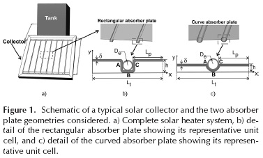
The rectangular geometry described in Figure 1b was taken as reference given that it is a common geometry in this type of collectors (Matrawy & Farkas, 1997). The curved plate geometry described in Figure 1c is a proposal of this work, with the presumption that it may increase the thermal efficiency of the absorber plate, mainly due to the increase in the tube-to-plate area of contact. Nominal geometric parameters used for both profiles correspond to a thickness (δ) of 0,79 mm; a total length of the representative unit cell (L) of 123,8 mm, a distance between tubes of the absorber plate (2Lp) of 108 mm (Lp = 54 mm), a profile height (h) of 17,5 mm for the rectangular geometry and h = 9,3 mm for the curved geometry, an exterior tube diameter (De) of 15,8 mm, and a fixed tube thickness of 1,4 mm. These nominal values were taken as the basis for modeling a "typical" solar collector, although a parametric analysis was carried out in which some of these values were varied.
Measurement of solar radiation
Aiming for calculations more representative of a real situation, the solar radiation received by the collector (Qr) was measured using a commercial pyranometer (Dynamax Inc. SPN1, model A619) placed horizontally on a flat unobstructed rooftop on January 26th 2014 in the city of Merida, Yucatan, Mexico (latitude 21° 01'19'' North, longitude 89° 37'36'' West, 9 m above sea level). The average temperature for that day was 32 °C, with an average relative humidity of 67 % and an average wind speed of 14 m/s. Total incident radiation was registered every 5 s to form a curve Qr as a function of time (t) for the entire day. This curve can subsequently be integrated between the desired times (t1 and t2) to obtain the net heat flow in a period of time ( r). This net heat flow was multiplied by the distance between the tubes of the absorber plate (2Lp) to obtain , i.e.,
The range of time selected herein corresponded to t1 = 12:00 and t2 = 14:00. The irradiation curve (not shown) had a parabolic shape centered around 12:00 h. Integrating such an irradiation curve according to Equation (1) yields a value of r = 786 W/ m2, which is used as a source of incident thermal energy in the finite element models.
Finite element modeling and calculation of the thermal efficiency
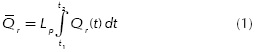
The use of the solution by analytical techniques with a well-known flat-plate solar collector of fin-and tube type to validated the finite element analysis (Duffie and Beckman, 2006). For the configuration of the fins to be studied, the numerical interaction of the finite element is used since there is no closed analytical solution.The finite element model of each of the investigated profiles was constructed using a commercial code, Ansys 13,0. A schematic representation of the model for both geometries is shown in Figure 2. Figure 2a shows a collector plate with the rectangular profile while Figure 2b presents the curved profile. The heat received through radiation (Qr), the convective heat losses from the collector to the air (Qc), and from the tube to the circulating fluid (Qca), as well as the insulating boundary conditions (Q = 0), are represented in this figure.
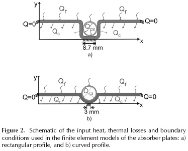
Due to the periodicity and constant width (out-of-plane dimension) of the plate, the representative volume element for both profiles corresponds to the bidimensional models shown in Figure 2. Two types of elements were used, denominated "PLANE55" and "PLANE35" in ANSYS. "PLANE55" corresponds to quadrilateral elements with temperature as degree of freedom and linear interpolation, while "PLANE35" corresponds to triangular elements of the same type. These elements are applicable to a thermal analysis in two dimensions and steady state. A nominal mesh of 14,662 elements was used, containing 6,885 rectangular elements and 7,777 triangular ones (see Figure 3). This number of elements was selected after a detailed convergence analysis, which proved that an increase in the number of elements to 16,902 does not produce significant changes in the temperatures or heat flows obtained. A finer (graded) mesh was used at and around the contact between the plate and tube in both geometries, in order to capture the heat flow values with greater numerical accuracy.
The smallest elements size at the tube/plate contacting the surface was of 0,013 mm x 0,09 mm, and the larger elements of 0,1 x 0,13 mm were used in the rest of the plate and tube, as shown in Figures 3a and 3b. 0,25 mm long triangular elements were generated inside the tube simulating the contained water. The profiles of rectangular and curved plates were subjected to an input heat flow of r = 786 W/ m2, obtained from the measurement of solar radiation and Equation (1). The coefficient of total heat losses through convection, conduction and radiation was set as 10,1 W/m2 °C for both profiles, which was calculated by means of the Klein (1975) and Duffie & Beckman equations (Duffie & Beckman, 2006; Garg & Rani, 1980), under conditions which represent a commercial solar collector with a glass cover and an inclination angle of 26°, glass and plate with emissivity of 0,88 and 0,95, respectively, and a wind speed of 14 m/s. This coefficient is used in the finite element model to calculate the thermal losses Qc .
Both profiles were modeled with the boundary condition of heat flow Q(x = 0) = Q(x = Lt) = 0, (see Figures 2a and 2b). Furthermore, in real conditions, the bottom of the collector is thermally insulated, and therefore for the central lines (8,7 mm for the rectangular one and 3 mm for the curved collector) corresponding to y = 0, zero heat flow was also considered (see Figures 2a and 2b). The whole perimeter of the upper surface of the absorber plate receives a heat flow Q, while convective heat losses Qc are imposed on the other free surfaces. For this steady state finite element model, "water" was simulated only as a convection solid at the interior of the tube, to account for convection between the tube and water.
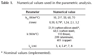
A convective coefficient at the water/tube interface of h = 21W/m2 °C was taken as a baseline, considering an outdoor temperature of Ta = 32 °C. However, values hca were varied between 10-70 W/m2 °C in the parametric analysis. A copper tube with a thermal conductivity of 401 W/m °C (Incropera & DeWitt, 2007) was also used for the baseline model and the thermal conductivity of the water inside the tube was set to 0,58 W/m2 °C. For the thermal conductivity of the plate (k), a baseline value of 51,9 W/m °C was used, corresponding to carbon-silicon steel, although this value was varied in the parametric analysis up to 401 W/m °C, representing different materials for the plate (see Table 1). The nominal thickness of the plate (δ) was 0,79 mm and varied in the parametric analysis from 0,5 to 3,17 (mm). The tube-to-tube distance in the absorber plate (Lp) was set to a nominal value of 5,4 cm and varied between 3 and 8 cm. The convective coefficient of the water (hca) varied from 10 to 70 W/m2 °C, with a nominal value of 21W/m2 °C. In this way, the baseline model is represented by a typical flat plate solar collector with a rectangular profile and plate conductivity of 51,9 W/m °C, a convective coefficient of the water of 21 W/m2 °C, a total heat loss coefficient of 10,1 W/ m2 °C, a thickness of 0,79 mm, a total segment length (Lt) of 123,8 mm, and a distance between tubes in the absorber plate (Lp) of 54 mm. These values correspond to a baseline model taken as a reference, and they vary in the parametric analysis in accordance to parameters listed in Table 1, in order to identify potential improvements in thermal efficiency.
One of the parameters of most interest in this model is the heat transmitted from the plate to the tube conducting the water (Qu, see Figure 3), since this represents the effective (or useful) heat which is used to heat the water in the collector. This useful heat transmitted from the plate to the tube (indicated in the inset of Figure 3) was calculated in the plate-tube contact areas, which are indicated with the letters A, B and C for the collector with rectangular profile (see Figures 1b and 3a). This contact was considered in the model with a length of l = 3 mm for each contact zone (A, B or C). In this configuration (rectangular profile), the total useful heat transmitted from the plate to the tube through these three points A, B, C, is expressed by,
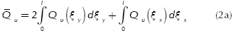
where the first term represents the heat transmitted at A (left) and C (right) and the second term represents the heat transmitted through B (at the bottom). It is important to point out that the contribution through A and C are equal by symmetry.
For the curved profile shown in Figures 1c and 3b, the contact between plate and tube is continuous and is therefore quantified by means of the angular variable θ (see Figures 3b). Point A in this configuration corresponds to θ = 0, point B to θ=Π/2 and point C to θ=Π. However, by symmetry, the useful heat transferred from the plate to the tube through the arch length between points AB is equal to that between points BC, so the total useful heat for the curved profile is obtained by,
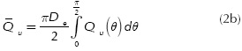
where De is the external diameter of the tube and ΠDe /2 the arch length of section AB.
In this way, the heat flow at the plate-tube interface (Qu) was obtained from the finite element model, and the net heat transferred through these borders was numerically calculated by using the areas under the curve of the diagrams Qu(ξ ) vs. ξ (Equation (2a)) and Qu(θ) vs. θ (Equation (2b)).
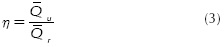
The thermal efficiency (η) of each configuration of the absorber plate was calculated dividing the net useful heat (u) (Equation (2a) or (2b)) by the irradiation received by the collector (Q Equation (1)), i.e.,
Results and discussion
Parametric analysis
The effect of the absorber plate thickness (δ) was investigated by varying the thickness from δ = 0,50 mm to δ = 3,2 mm (see Table 1). The normalized heat flow (Q ) at the plate-tube contact surface identified by section A for the rectangular profile, and section AB for the curved profile, is shown in Figure 4a and Figure 4b, respectively. It is important to note that the lengths of the plate-tube contact for the rectangular and curved profiles are different. For the rectangular profile, each of its three contact areas (A,B,C) is 3 mm long, rendering a total contact length of 9 mm; in the case of the curved profile, the total arch length of the plate-tube contact ABC is 24,8 mm.
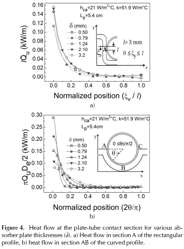
By symmetry, the heat flow in segments A and C of the straight profile are equal (see Figures1b and 3a), and the same symmetry arguments apply for sections AB and BC of the curved profile (see Figures 1c and 3b). In contrast, in the lower segment B of the straight profile (see Figures 1b and 3a), the heat flow is negligible. In Figures 4a heat flow at section A reaches a maximum at the upper contact point (ξy /l = 0), decreasing exponentially towards zero at ξ /l = l. This is due to the fact that the irradiation reaches the absorber plate from the top and, given the high thermal conductivity of the material of the plate, it reaches a rapid thermal balance at the tube. Although the curves seem overall similar, Qu is higher as δ increases, but it reaches a plateau after certain thickness.
A more detailed analysis is provided by the analysis of the area under the curves, as discussed herein. For the curved profile in Figure 4b the heat flow through the section AB reaches a maximum at the upper contact point (θ=0), and reduces exponentially towards zero at θ=Π/2. This is also due to the fact that the incident radiation is absorbed by the upper part of the collector plate and the heat flow quickly moves towards B, reaching thermal balance. Comparing Figures 4a and 4b it is observed that the curved profile presents higher useful heat values with respect to a straight profile with the same thicknesses.
Similar parametric analyses were conducted to investigate the influence of the thermal conductivity of the absorber plate, the distance between tubes, and the convective coefficient of water. The results of this parametric investigation are summarized in the form of curves of efficiency, and presented in the following section.
Comparison of thermal efficiency
In order to obtain a more detailed parametric analysis and a direct comparison of the performance of both absorber plate profiles, the thermal efficiency of the solar collector was calculated by Equation (3) as a function of the plate thickness (δ), thermal conductivity (k), (half) distance between tubes of the absorber plate (Lp), and the convective coefficient of water (hca), as shown in Table 1.
Figure 5a presents the thermal efficiency (η) as a function of the plate thickness (δ), from δ = 0,5 mm to δ = 3,17 mm, maintaining k, Lp and hca constant at their nominal values, as indicated in Table 1. For both profiles, the thermal efficiency of the collector plate increases as the thickness of the plate increases.
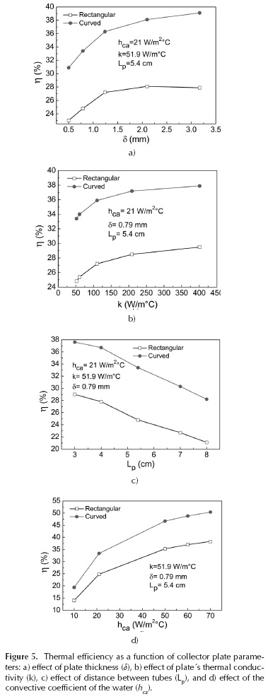
The increase in η is pronounced from δ≤; 2 mm and seems to level off after such a thickness. Regardless of the thickness, the curved profile is 25-28 % more efficient than the rectangular profile.
For the plate's thermal conductivity (k) (Figure 5b), an increase in k yields an increase in thermal efficiency which is more pronounced for plate materials with k ≤ 200 W/m °C. A comparison between carbon steel (k = 60,5 W/m °C, see Table 1) and aluminum (k = 209 W/m °C), yields larger thermal efficiency for aluminum of the order ∼ 8 %. After k=200 W/m °C, increasing k yields only marginal increases in j, suggesting that plate materials with k ∼ 200 W/m °C may suffice. Regardless of k, the curved profile is always 22-25 % more thermally efficient than the rectangular one. Figure 5c describes the behavior of both absorber plate profiles when the distance between tubes of the plate (2Lp) is varied from Lp = 3 cm to Lp = 8 cm. The thermal efficiency decreases almost linearly as the distance between tubes increases. This highlights the difficulty of the heat to transmit its energy to the tube from relatively long distances. This suggests that a higher density of tubes per unit area (or length) of the absorber plate would enhance its thermal efficiency. In practice, however, a greater density between tubes per unit length/area of the collector may be limited by the manufacture feasibility and would probably increase production costs. Similar conclusions have been reached in previous optimization works of fin geometries in a flat plate solar collector (Hahne, 1985; Viorel, 2006). It is also observed in Figure 5c that for any Lp the curved profile consistently presents higher efficiencies (22-25 %) than the rectangular profile. In Figure 5d it is seen that an increased water flow, represented by an increased convective coefficient of the water (h ) increases the thermal efficiency of the collector. The curved profile is 24-27 % more efficient than the rectangular profile. This suggests that an increase in the mass flow of water circulating through the collector's tubes, would promote more heat exchange, thereby contributing positively to the efficiency of the system (see Joudi & Abd-Alzahra, 1984).
Conclusions
This work investigated the thermal behavior of an absorber plate as part of a solar collector by means of a numerical analysis based on the finite element method. The thermal behavior and thermal efficiency of two absorber plate geometries were studied, using a typical solar collector with a rectangular absorber plate as reference and a proposed one with a curved geometry. A representative volume element of the absorber plate was established for the finite element model and a parametric analysis was conducted to identify the influence of the most important factors. The finite element analysis suggests that by modifying the rectangular profile to a curved one with greater contact surface between the plate and its tubes the thermal efficiency is significantly improved. From the collector analysis, the increase in thermal efficiency can be as high as 20-28% when the curved profile is used, depending on the selection of plate's geometric and material parameters. The modeling results suggest that a curved profile made of materials such as aluminum (k ≥ 200 W/m °C), with plate thickness of the order of 2-3 mm and with a large density of tubes per unit area of the collector's plate, would greatly benefit the thermal efficiency of the collector.
Acknowledgements
This work was financed by CONACYT through the regional emergent research groups project 2014 (GIRE-2014) No. 235637. D.M. Medina Carril thanks PRODEP for the scholarship UTMY-017 providing economic support for his doctoral studies and this work. Technical assistance of Ricardo Gamboa, Joel Garcia and Antonio Hernández is appreciated. General advice and help with figure edition by Jesus Ku, JJ Espadas, Genaro Soberanis and Luis Peraza is strongly appreciated.
References
Abdolzadeh, M., & Mehrabian, M. A. (2011). Heat gain of a solar collector under an optimum slope angle in Kerman, Iran. Energy Sources, Part A: Recovery, Utilization, and Enviromental Effects, 33, 1375-1385. DOI: 10.1080/15567036.2010.499417. [ Links ]
Abdolzadeh, M., & Mehrabian, M. A. (2012). The optimal slope angle for solar collectors in hot and dry parts or Iran. Energy Sources, Part A: Recovery, Utilization, and Enviromental Effects, 34, 519-530. DOI: 10.1080/15567036.2011.576413. [ Links ]
Alvarez, A., Cabeza, O., Muniz, M.C., & Varela, L.M. (2010). Experimental and numerical investigation of flat-plate solar collector. Energy, 35, 3707-3716. DOI: 10.1016/j.energy.2010.05.016. [ Links ]
Duffie, J. A., & Beckman, W. A. (2006). Solar engineering of thermal processes. Third ed. New York: Wiley & Sons. [ Links ]
Eisenmann, W., Vajen K., & Ackermann, H. (2004). On the correlations between collector efficiency factor and material content of parallel flow flat-plate solar collectors. Solar Energy, 76, 381-387. DOI: 10.1016/j.solener.2003.10.005. [ Links ]
Garg, H. P., & Rani, U. (1980). Loss coefficients from solar flat-plate collectors. Applied energy, 7, 109-117. DOI: 10.1016/0306-2619(80)90052-5. [ Links ]
Hahne E. (1985). Parameter effects on design and performance of flat plate solar collectors. Solar energy, 34 (6), 497-504. DOI: 10.1016/0038-092X(85)90023-4. [ Links ]
Hollands, K.G.T., & Stedman, B.A. (1992). Optimization of an absorber plate fin having a step-change in local thickness. Solar Energy, 49, 493-495. DOI: 10.1016/0038-092X(92)90157-6. [ Links ]
Hottel, H.C., & Woertz, B.B. (1942). Performance of a flat-plate solar-heat collectors. Trans ASME, 64, 91-104. [ Links ]
Hottle H.C., Whiller A. (1958). Evaluation of flat-plate solar collector performance. Transaction of conference on the use of Solar Energy, University of Arizona, 2, 74-104. [ Links ]
Incropera, F.P., DeWitt, D.P., & Bergman, T.L. (2007). Fundamental of heat and mass transfer. 6th. Ed. Hoboken, NJ: John Wiley & Sons. [ Links ]
Joudi, K. A., & Abd-Alzahra, H. A. A. (1984). An experimental investigation into the performance of a domestic forced circulation solar water heater under varying operating conditions. Energy Conversion Management, 24 (4), 377-384. DOI: 10.1016/0196-8904(84)90017-7. [ Links ]
Klein, S. A. (1975). Calculation of flat-plate loss coefficients. Solar energy, 17, 79-80. DOI: 10.1016/0038-092X(75)90020-1. [ Links ]
Kovarik, M. (1978). Optimal distribution of heat conducting material in the finned pipe solar energy collector. Solar Energy, 21 , 477-484. DOI: 10.1016/0038-092X(78)90071-3. [ Links ]
Kundu, B. (2002). Performance analysis and optimization of absorber plates of different geometry for a flat-plate solar collector: a comparative study. Applied thermal engineering, 22, 999-1012. DOI: 10.1016/S1359-4311(01)00127-2. [ Links ]
Kundu, B. (2008). Performance and optimum design analysis of absorber plate fin using recto-trapezoidal profile. Solar Energy, 88, 22-32. DOI: 10.1016/j.solener.2007.05.002. [ Links ]
Lamnatou, Chr., Mondol, J.D., Chemisana, D., & Maurer C. (2016). Modelling and simulation of Building-Integrated solar thermal systems: Behaviour of the system. Renewable and Sustainable Energy Reviews, 45, 36-51. DOI: 10.1016/j.rser.2015.01.024. [ Links ]
Leone, G., & Beccali, M. (2016). Use of finite element models for estimating thermal performance of façade-integrated solar thermal collectors. Applied Energy, 171 , 392-404. DOI: 10.1016/j.apenergy.2016.03.039. [ Links ]
Matrawy, K.K., & Farkas, I. (1997). Comparison study for three types of solar collectors for water heating. Energy Conversion and Management, 38, 861-869. DOI: 10.1016/S0196-8904(96)00089-1. [ Links ]
Mohsen, M. S., Al-Ghandoor, A., & Al-Hinti, I. (2009). Thermal analysis of compact solar water heater under climatic conditions. International Communications in Heat and Mass Transfer, 36, 962-968. DOI: 10.1016/j.icheatmasstransfer.2009.06.019. [ Links ]
Nahar, N.M., & Gupta, J.P. (1989). Studies on gap spacing between absorber and cover glazing in flat plate solar collectors. International Journal Energy Research, 13, 727-732. DOI: 10.1002/er.4440130611. [ Links ]
Rama, S. R. G. (1997). Finite element analysis of a flat plate solar collector. Finite Elements in Analysis and Design, 24, 283-290. DOI: 10.1016/S0168-874X(96)00067-4. [ Links ]
Rommel, M., & Moock, W. (1997). Collector efficiency factor F' for absorbers with rectangular fluid ducts contacting the entire surface. Solar Energy, 60, 199-207. DOI: 10.1016/S0038-092X(97)00006-6. [ Links ]
Selmi, M., Al-Khawaja, M.J., & Marafia, A. (2008). Validation of CFD simulation for flat plate solar energy collector. Renewable energy, 33, 383-387. DOI: 10.1016/j.renene.2007.02.003. [ Links ]
Soteris, A. K. (2009). Solar Energy Engineering Processes and Systems. 1st ed. San Diego, California: Academic Press. [ Links ]
Shukla, R., Sumathy, K., Erickson, P., & Gong, J. (2013). Recent advances in the solar water heating systems: A review. Renewable and Sustainable Energy Reviews, 19, 173-190. DOI: 10.1016/j.rser.2012.10.048. [ Links ]
Ulgen, K. (2006). Optimum tilt angle for solar collectors. Energy Sources, Part A: Recovery, Utilization, and Environmental Effects, 28(13), 1171-1180. DOI: 10.1080/00908310600584524. [ Links ]
Viorel, B. (2006). Optimum fin geometry in flat plate solar collector systems. Energy Conversion and Management, 47, 2397-2413. DOI: 10.1016/j.enconman.2005.11.006. [ Links ]
Yeh, H.M., Ho, C.D., & Yeh, C.W. (2003). Effect of aspect ratio on the collector efficiency of sheet-and-tube solar water heaters with the consideration of hydraulic dissipated energy. Renewable Energy, 28, 1575-86. DOI:10.1016/S0960-1481(03)00006-5. [ Links ]

