


Services on Demand
Journal
Article
 English (pdf)
 Article in xml format
 Article references
 Send this article by e-mail
Indicators
-
 Cited by SciELO
 -
 Access statistics
Related links
-
 Cited by Google
 -
 Similars in
SciELO
Similars in
SciELO -
 Similars in Google
Share

 Permalink
Ingeniería e Investigación
Print version ISSN 0120-5609
Ing. Investig. vol.36 no.3 Bogotá Sep./Dec. 2016
https://doi.org/10.15446/ing.investig.v36n3.56610
DOI: http://dx.doi.org/10.15446/ing.investig.v36n3.56610
Investigating the influence of infill percentage on the mechanical properties of fused deposition modelled ABS parts
Investigando la influencia del porcentaje de relleno en las propiedades mecánicas, de elementos impresos con ABS por el método de modelado por deposición fundida
Kenny L. Alvarez C.1, Rodrigo F. Lagos C.2, and Miguel Aizpun3
1 Mechanical Engineer, Pontifícia Universidad Católica de Valparaiso, Chile. Affiliation: Assistant professor, Pontifícia Universidad Católica de Valparaiso, Chile. E-mail: kenny.alvarez@pucv.cl.
2 PhD in Mechanical Engineering, Tecnun-Universidad de Navarra, Spain. Affiliation: Assistant professor, Pontifícia Universidad Católica de Valparaiso, Chile. E-mail: rodrigolagoscereceda@gmail.com.
3 MSC, PhD in Mechanical Engineering, Tecnun-Universidad de Navarra, Spain. Affiliation: Assistant professor, Pontifícia Universidad Católica de Valparaiso, Chile. E-mail: miguel.aizpun@pucv.cl.
How to cite: Alvarez, K. L., Lagos, R. F., & Aizpun, M. (2016). Investigating the influence of infill percentage on the mechanical properties of fused deposition modelled ABS parts. Ingeniería e Investigación, 36(3), 110-116. DOI: 10.15446/ing.investig.v36n3.56610
ABSTRACT
3D printing is a manufacturing process that is usually used for modeling and prototyping. One of the most popular printing techniques is fused deposition modeling (FDM), which is based on adding melted material layer by layer. Although FDM has several advantages with respect to other manufacturing materials, there are several problems that have to be faced. When setting the printing options, several parameters have to be taken into account, such as temperature, speed, infill percentage, etc. Selecting these parameters is often a great challenge for the user, and is generally solved by experience without considering the influence of variations in the parameters on the mechanical properties of the printed parts.This article analyzes the influence of the infill percentage on the mechanical properties of ABS (Acrylonitrile Butadiene Styrene) printed parts. In order to characterize this influence, test specimens for tensile strength and Charpy tests were printed with a Makerbot Replicator 2X printer, in which the infill percentage was varied but the rest of the printing parameters were kept constant. Three different results were analyzed for these tests: tensile strength, impact resistance, and effective printing time. Results showed that the maximum tensile force (1438 N) and tensile stress (34,57 MPa) were obtained by using 100 % infill. The maximum impact resistance, 1,55 J, was also obtained with 100 % infill. In terms of effective printing time, results showed that printing with an infill range between 50 % and 98 % is not recommended, since the effective printing time is higher than with a 100 % infill and the tensile strength and impact resistance are smaller. In addition, in comparing the results of our analysis with results from other authors, it can be concluded that the printer type and plastic roll significantly influence the mechanical properties of ABS parts.
Keywords: 3D printing, mechanical properties, FDM process, ABS, makerbot replicator 2X.
RESUMEN
La impresión 3D es un proceso de manufactura que se basa en la fabricación de prototipos, partes y piezas funcionales. Existen diferentes métodos, en los cuales se utilizan distintos materiales en diversos formatos. Uno de los métodos más utilizados es el modelado por deposición fundida (FDM). A pesar de las ventajas que posee con respecto a otros procesos de fabricación, la impresión 3D no está libre de dificultades o problemas. Al momento de configurar una impresión, se deben ingresar parámetros para cada una de las variables presentes en el proceso, como por ejemplo: temperatura, velocidad, porcentaje de relleno, etc. La elección de dichos parámetros muchas veces resulta ser un problema para el operador, y generalmente se realiza en función de su experiencia, sin considerar la influencia que estos parámetros tendrán en las propiedades mecánicas del elemento terminado. Este trabajo analiza la influencia del porcentaje de relleno en la resistencia mecánica de piezas fabricadas en ABS (Acrilonitrilo Butadieno Estireno). Para ello, se imprimieron probetas para ensayo de tracción y Charpy, variando el porcentaje de relleno, y manteniendo los demás parámetros constantes. Seguido de esto, se ensayaron las probetas para obtener los valores de resistencia a la tracción y resistencia al impacto. Esto se realizó con una impresora Makerbot Replicator 2X. Además, se analizó el tiempo efectivo de impresión para conocer la variabilidad de este parámetro al modificar el porcentaje de relleno.Este estudio permitió determinar la fuerza resistente máxima que se obtuvo con un porcentaje de relleno de 100 %, fue de (1438 N), con una resistencia de (34,57 MPa). La máxima resistencia al impacto se obtuvo también con 100 % de relleno fue de 1,55J. En cuanto al tiempo de impresión, los resultados son bastante interesantes, ya que se logró identificar que en el intervalo de 50 a 98 % de relleno no es conveniente imprimir, ya que el tiempo de impresión es mayor que con 100 %, y la resistencia a la tracción y al impacto son menores, por lo que no se justifica efectuar impresiones en ese rango de porcentaje de relleno.
Palabras clave: Impresión 3D, propiedades mecánicas, proceso FDM, ABS, Makerbot Replicator 2X.
Received: March 30th 2016 Accepted: November 18th 2016
Introduction
3D printing is a manufacturing process based on layer addition, and has a number of benefits with respect to other similar manufacturing processes. This technique has prevailed since it is rather easy to produce complete parts (Caulfield 2007), and this has led to a huge reduction in part manufacturing periods, as even the post-processing of these final parts can be eliminated (Sood 2010). Moreover, this technique has several other advantages, including the wide range of materials that can be used, the possibility of manufacturing highly complex parts, and the low acquisition and manufacturing costs (Chua 2003; Sood 2010).
These advantages have led to widespread dissemination of this technique among designers, scientists, engineers, and students due to its wide application range.
Although 3D printing was developed more than two decades ago, its potential has been exploited in only the last 5-10 years. This boom was possible because of the great advances made in the hardware, software and materials fields, which significantly reduced acquisition costs, which now start at 700 US dollars (USD) and go up to 10 000 USD.
Thanks to the popularity of 3D printing, it is now being analyzed by economists, who predicted that in 2015 this market generated around 3,8 billion USD (Credit Suisse, 2013), and that by 2021 it will rise to 10,8 billion USD, meaning that in only 6 years there will be an increase of 184 %. One of the main reasons of this huge increase is the expiration of the FDM printing process patent in 2009.
State of the art
Fused Deposition Modeling (FDM) is one of the most popular 3D printing methods. This manufacturing technique consists of adding several layers by extruding and laying a melted material, normally ABS or PLA plastics. The printing material, which is initially structured as a filament, is extruded through a highly heated nozzle, melting the filament and laying it on a platform. At the same time, the nozzle structure describes a rectilinear movement on a plane in order to generate the geometry of the part, layer by layer. Each pass corresponds to a layer of the melted material, which is bound to the adjacent layer by the thermal energy produced in the melting process.
Once the part has been manufactured, the structure consists of anisotropic laminas (Es-Said 2000), which means that the final product will have different mechanical properties depending on the direction.
The FDM process allows for control of the mechanical properties by varying printing parameters such as layer thickness, laying direction, number of shells, distance between nozzle and platform, etc.
Several researchers have analyzed the printing process' parameters and its effects on the product's properties, superficial roughness, etc. This manufacturing process includes the melting and solidification of the material, which leads to the generation of residual stresses. These stresses are generated in the material due to the temperature gradient and contraction that are produced during the process. Kantaros & Karalekas (2013) studied the influence of layer thickness and printing orientation on the residual strain, concluding that the residual strain is minimal when using a longitudinal orientation (0°) and a layer thickness of 0,25 mm.
In addition, it is known that parts printed using the FDM method show an emptiness percentage inside these parts, i.e. there are small volumes inside the product that are not filled with the extruded material. This effect is caused by the sudden directional changes in the process and appears mainly in the areas close to the external surface of the part.
This phenomenon can be reduced by increasing the extrusion temperature. Gajdoš & Slota (2013) show that if the extrusion temperature is increased from 280 °C up to 290 °C, the empty zone volume decreases from 15,86 % to 11,17 %. Moreover, if the ambient temperature is increased from 70 °C to 75 °C, this percentage decreases even more, to 10,34 % (considering a constant extrusion temperature of 290 °C).
The filament bond is produced by the adhesion of the melted material. This process is gradual and depends on time and temperature. When a melted filament comes into contact with a partially melted one, a neck is produced in the interface, which grows with time. Several works (Bellehumeur 2004; Li 2002) show that if the temperature is sufficiently high for longer than the specified time, the neck grows to the size of the filament diameter.
In addition, other studies (Li n.d.; Rodriguez 2003) show that the adhesion resistance of the filaments is smaller than the nominal ABS resistance, and therefore it is expected that the mechanical properties of the printed parts will differ from those of nominal ABS material.
In order to overcome this problem, recent advances (Nikzad 2011) have led to the development of new printing materials, mixing ABS with small particles of Fe and Cu, and thus modifying the mechanical properties of the printed parts. Moreover, carbon fiber reinforced plastic has been developed for improving the mechanical properties (Ning, F., 2015).
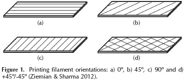
Another printing parameter that has been analyzed is filament orientation during the printing process (Ziemian & Sharma, 2012). Four different orientations were studied: 0°, 45°, 90° and +45°/-45° (see Figure 1) in order to compare the tensile strengths. The 0° oriented parts yielded the highest tensile strength, reaching up to 25,72 MPa, since the test force was applied along the filament direction. On the contrary, the specimen that showed the smallest resistance was the one with a 90° filament orientation.
In addition to the analysis of the above parameters, Weinmann (2003) checked the influence of all the printing parameters simultaneously, using a factorial DoE methodology in order to choose the best possible combination for obtaining improved mechanical properties in the final parts. Other authors have worked with DoE in order to know the influence of printing parameters (Montero 2001).
Tymrak (2014) characterized the mechanical properties of test specimens printed with ABS and PLA, taking into account different layer thicknesses and filament orientation values (the rest of the parameters had constant values and 100 % filling). Results showed that the +45°/-45° orientation and 0,2 mm layer thickness values yielded the best tensile strength test results. Furthermore, the specimens printed with 0,4 mm layer thickness and the ones with 0/90° orientations showed the highest elastic modulus during the tests.
Although the above mentioned studies have identified some optimum values for the various printing parameters, and even if there are several studies that contribute to the knowledge of their mechanical properties (Torres 2015; Lužanin 2014; Montero 2001; Ahn 2002; Lee 2007; Bellini & Güçeri, 2003; Durgun & Ertan, 2014), there are still uncertainties regarding certain other parameters, which can be obstacles for users. One such parameter is the infill percentage.
When setting the printing parameters, the infill percentage of the part, i.e. the amount of printed material that the printed part will have inside it, needs to be specified. This parameter can vary from 0 % up to 100 %. When the setting is 0 %, the printed part will only have an external surface (which will depend only on the number of shells) but it won't have any printed material inside the external surface. If the percentage value is higher than 0 %, the machine will lay material inside the part, using a specific laying geometry pattern that will depend on the printer manufacturer. The majority of printers (including the one analyzed in this work) use a default hexagonal building pattern, although sometimes the printer allows different printing geometrical patterns to be used.
Methodology
The aim of this article is to analyze the influence of the infill percentage on the mechanical properties of parts printed using the fused deposition modeling method and a Makerbot Replicator 2X printer. Three different issues regarding variation in the infill parameter were studied: maximum tensile force, maximum impact force and effective printing time.
ABS test specimens were manufactured according to ASTM D638-10, Standard Test Method for Tensile Properties of Plastics, and ASTM D6110-10, Standard Test Method for Determining the Charpy Impact Resistance of Notched Specimens of Plastics, and they were submitted to tensile strength and Charpy tests according to the respective standards.
The test specimens were manufactured with a li near 5 % increase in infill percentage, starting at 0 % and going up to 100 %, while keeping the other printing parameters constant:
- Platform temperature: 125 °C.
- Extrusion temperature: 250 °C.
- Print speed: 90 [mm/s].
- Travel speed: 150 [mm/s].
- Number of shells: 2.
- Layer thickness: 0,2 [mm].
- Nozzle diameter: 0,4 [mm].
- Printing pattern: hexagonal.
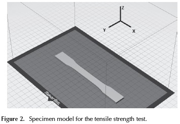
Five test specimens were printed for each infill condition. However, some specimens were reprinted due to inappropriate behavior during the tensile strength tests (such as breaking out of the reduced area). In total, 108 test specimens were printed for the tensile strength test and 105 for the Charpy test. The specimen orientation is shown in Figure 2.
In addition to the tensile strength and Charpy tests, the effective printing time was also analyzed due to its relevance in the manufacturing process. This parameter corresponds to the time taken by the printer to completely print a part, subtracting the nozzle and platform heating times. In order to quantify this parameter, the nozzle and platform heating times were noted down during the printing of the test specimens, and then subtracted from the final printing times, which are shown in the printer display once the printing process has finished.
Tensile strength tests
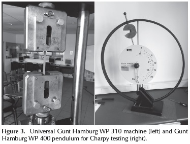
Tensile strength tests were performed according to the procedure detailed in ASTM D638-10. A Universal Gunt Hamburg WP 310 machine with a 50 kN force range was used for these tests (Figure 3, left). The test speed was set to 2 mm/s.
Charpy tests
Charpy tests were performed according to ASTM D6110-10 with a Gunt Hamburg WP 400 pendulum (see Figure 3, right). Three tests were performed without test specimens in order to calculate the energy loss due to component friction and wind resistance. The notching was produced during the printing process.
Results and discussion
Table 1 shows the results from the tensile strength and Charpy tests. As can be observed, for most of the infill percentages, 5 specimens were tested, although for some cases more specimens were needed, as explained previously. The following results are presented in Table 1: mean maximum tensile force, mean impact resistance and standard deviations for each set of 5 test specimens.
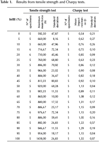
The results were, in some specimen sets, rather scattered. Thus, the maximum tensile force (tensile strength test) and maximum absorbed energy (Charpy test) were quite different from the mean calculated values. When looking for the causes of this spread, it was observed that these extreme values were obtained when printing the test specimens with a different filament color. Therefore, the results obtained with this different color were erased from the final results and calculations.
As can be observed in the curve (Figure 4), the tested material has a linear stress variation, which corresponds to the elastic behavior of the ABS plastic (Tymrak 2014). The test specimens reach a maximum strength of (34,57 MPa), for a deformation of approximately 0,034 [mm/ mm]. When the applied force is increased, the strength decreases slightly, until the sudden decrease at 0,063[mm/ mm] deformation, as a result of the material fracture.
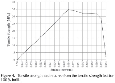
The behavior shown in Figure 4 agrees with the ABS tensile strength-strain results shown by other authors (Lokensgard, 2010). However, the measured maximum strength is different from the one measured in other tests (Li 2001; Rodríguez 2003).
Figure 5 shows the maximum mean force vs. infill percentage for the tensile strength tests. The reason for using the force instead of strength is because the specimen resistant area isn't the cross specimen area, except for the case of specimen fabricated with 100 % infill. As can be observed, the maximum mean force increases when the infill percentage is increased, which would be expected since the higher the infill percentage, the higher the resistance area. In some cases, when the infill percentage was increased, the force remained constant or even slightly decreased. This unexpected behavior can be explained by uncertainties during the printing process that can't be completely controlled: distance between nozzle and platform, nozzle alignment, platform alignment, uniform temperature on the platform surface, etc. Small variations in these parameters can influence the manufacturing process of the test specimens, showing that the variability of this process can be significant.
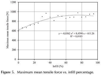
Nevertheless, the curve shows an increasing trend as the infill percentage values increase. However, this trend experiences an abrupt increase when changing from 95 % to 100 % infill, where the force varies from 954 N up to 1438 N, which is almost a 50 % increase. The 100 % infill result was removed (in both tests) because the printing pattern was different with respect to the other specimens. In this case, the printing pattern was lineal paralell to X and Y printing direction.
The curve that is shown in Figure 5 is an order 2 polynomial, since a linear approximation gives R results smaller than 0,8. One conclusion from this trend is that the tensile strength of parts manufactured with this method will increase gradually when increasing the infill percentage between 0 and 95 %.
The influence of the infill percentage on impact resistance was analyzed by using the Charpy test results (Figure 6). As can be observed, this relationship is almost linear, i.e. the impact resistance is proportional to the infill percentage.
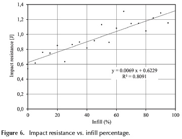
Results show that the maximum impact resistance, 1,55 J, is obtained when using 100 % infill.
Figure 6 also shows that there is an unexpected impact resistance decrease in some of the test specimens when the infill percentage is increased. This is caused by the uncertainties of the printing parameters, as was explained for the case of the tensile strength tests.
In addition, Figure 7 shows the variation of the effective printing time with respect to the infill percentage. Results show that the effective time varies almost linearly when increasing the infill percentage with the range from 0 to 95 %. This effect was expected: since if the infill percentage is increasing linearly, the infill material will also increase linearly, as will the time that the nozzle spends extruding the material and placing it layer by layer. However, when printing with 100 % infill, the effective printing time drastically reduces and equals the effective time of a 45 % infill test specimen.
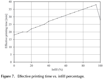
In order to analyze this unexpected phenomenon, the printing process was inspected visually, and it was concluded that the manufacturing process for a 100 % infill is different than the one used for smaller infill percentages. With 100 % infill, the printer moves linearly on the X and Y axes, and thus the resulting infill consists of alternating filament layers oriented in these 2 directions, i.e. one layer will have X-oriented filaments and the other layer will have Y-oriented filaments. This pattern is set only for infill percentages between 99 and 100 %.
In contrast, when a smaller infill percentage is set, the infill printing consists of a hexagonal pattern. The size of the hexagons will depend on the infill percentage that is set: the higher the infill percentage the smaller the infill hexagons.
This manufacturing difference has a significant effect on the effective printing time. As can be observed in Figure 7, the effective printing time for a 100 % infill part will be the same as for a 45 % infill part. However, when the infill percentage is between 50 % and 98 %, the effective printing time will be longer than for 100%. This is caused by the size of the hexagons, since when the infill percentage is high, the size of the hexagons is small and the nozzle has to travel a longer distance to print the same element.
It is important to be aware that the printing software gives an estimation of the printing time, and in general it is rather accurate. However, when using a 99-100 % infill, the estimation error is significant because it doesn't take into account the time reduction due to the change of geometry pattern, and instead it considers that the time increase is proportional to the infill percentage increase.
Conclusions
According to the results, the maximum tensile strength force for ABS parts, 1438 N, is reached at 100 % infill. Moreover, the maximum tensile stress for 100 % infill parts is (34,57 MPa).
Furthermore, the maximum impact resistance, obtained with Charpy tests, is 1,55 J, again with 100 % infill. However, it was also determined that the mechanical properties will not be always constant, since there are several uncertainties due to other printing parameters that are difficult to control.
It is also interesting to compare these results with the ones that are available in the literature for the same material (ABS) but different printers. Results from Tymrak 2014 show that the mean tensile stress for 100 % infill is 28,5 MPa, which is significantly smaller than the (34,57 MPa) result obtained in our tests. From this it can be concluded that the printer type or printer manufacturer, as well as the plastic roll manufacturer, are parameters than can significantly influence the mechanical properties of the printed parts.
In addition, another important contribution of this study is the analysis of the effective printing time. Generally, 3D printing users select smaller infill in order to reduce printing time or save material. However, according to our results, some general recommendations can be given for this Makerbot Replicator 2X printer (and it may be extended to other printers):
-
When looking for fast printing but not mechanical resistance, small infill percentages are recommended.
-
If a user wants high mechanical resistance and a fast process, it is preferable to use 100 % infill.
-
In general, infill values between 50 % and 98 % are not recommended, since the gains in mechanical resistance are countered by longer effective printing times.
Moreover, it is recommended to increase the extrusion temperature for ABS from 230 °C to 250 °C in order to obtain the best possible results during experimental studies and investigations.
Another recommendation is that for small parts or parts with complex geometries, it is recommended that the travel speed be reduced in order to avoid deformed parts.
Acknowledgements
This work was financed by the PMI UCV1301 project, from Universidad Católica de Valparaiso.
References
Ahn, S.-H., Montero M., Odell D., Roundy S. & Wright P.K. (2002). Anisotropic material properties of fused deposition modeling ABS. Rapid Prototyping Journal, 8(4), 248-257. DOI: 10.1108/13552540210441166. [ Links ]
ASTM D6110-10: "Standard test Method for Determining the Charpy Impact Resistance of Notched Specimens of Plastics". [ Links ]
ASTM D638-10: "Standard test Method for Tensile Properties of Plastics". [ Links ]
Bellehumeur, C., Li. L., Sun Q. & Gu P. (2004). Modeling of Bond Formation Between Polymer Filaments in the Fused Deposition Modeling Process. Journal of Manufacturing Processes, 6(2), 170-178. DOI: 10.1016/S1526-6125(04)70071-7. [ Links ]
Bellini, A. & Güçeri, S. (2003). Mechanical characterization of parts fabricated using fused deposition modeling. Rapid Prototyping Journal, 9(4), 52-264. DOI: 10.1108/13552540310489631. [ Links ]
Caulfield, B., McHugh, P.E. & Lohfeld, S. (2007). Dependence of mechanical properties of polyamide components on build parameters in the SLS process. Journal of Materials Processing Technology, 182(1-3), 477-488. DOI: 10.1016/j.jmatprotec.2006.09.007. [ Links ]
Chua, C.K., Leong, K.F. & Lim, C.S. (2003). Rapid Prototyping. Credit Suisse (September 18, 2013). 3D printing market will be much bigger than what industry consultants estimate Re-trieved from: http://www.3ders.org/articles/20130918-credit-suisse-3d-printing-market-will-be-much-bigger-than-what-industry-consultants-estimate.html. [ Links ]
Durgun, I. & Ertan, R. (2014). Experimental investigation of FDM process for improvement of mechanical properties and production cost. Rapid Prototyping Journal, 20(3), 228-235. DOI: 10.1108/RPJ-10-2012-0091. [ Links ]
Es-Said, O., Noorani, R., Mendelson, M., Foyos, J., and Mar-loth, R. (2000). Effect of Layer Orientation an Mechanical Properties of Rapid Prototyped Samples, Materials and Manufacturing Processes, 15(1), 107-122 DOI: 10.1080/10426910008912976. [ Links ]
Gajdoš, I. & Slota, J. (2013). Influence of printing conditions on structure in FDM prototypes. Technical Gazette, 20(2), 231-236. [ Links ]
Kantaros, A. & Karalekas, D. (2013). Fiber Bragg grating based investigation of residual strains in ABS parts fabricated by fused deposition modeling process. Materials and Design, 50, 44-50. DOI: 10.1016/j.matdes.2013.02.067. [ Links ]
Lee, C.S., Kim S.G., Kim H.J. & Ahn S.H. (2007). Measurement of anisotropic compressive strength of rapid prototyping parts. Journal of Materials Processing Technology, 187- 188, 627-630. DOI: 10.1016/j.jmatprotec.2006.11.095. [ Links ]
Li, L., Sun Q., Bellehumeur C. & Gu P. (2002). Composite modeling and analysis of FDM prototypes for design and fabrication of functionally graded parts. Journal of Manufacturing Processes, 4(2)129-141. DOI: 10.1016/S1526-6125(02)70139-4. [ Links ]
Li, L., Sun Q., Bellehumeur C. & Gu P. (2002). Investigation of Bond Formation in FDM Process. Solid Freeform Fabrication Proceedings, (403), 400-407. [ Links ]
Lokensgard, E. (2010). Industrial Plastics: Theory and Applications, 5th Edition, Delmar Cengage Learning, New York. [ Links ]
Lužanin, O., Movrin, D. & Plan, M. (2014). Effect of Layer Thickness, Deposition Angle, and Infill on Maximum Flexural Force in Fdm-Built Specimens. Journal for Technology of Plasticity, 39(1), 49-58. [ Links ]
Montero, M., Roundy, S. & Odell, D. (2001). Material characterization of fused deposition modeling (FDM) ABS by designed experiments. Proceedings of Rapid Prototyping & Manufacturing Conference, 1-21. [ Links ]
Nikzad, M., Masood, S.H. & Sbarski, I. (2011). Thermo-me-chanical properties of a highly filled polymeric composites for Fused Deposition Modeling. Materials and Design, 32(6), 3448-3456. DOI: 10.1016/j.matdes.2011.01.056. [ Links ]
Ning, F., Cong, W., Qiu, J., Wei, J., & Wang, S. (2015). Additive manufacturing of carbon fiber reinforced thermoplastic composites using fused deposition modeling. Composites Part B: Engineering, 80, 369-378. DOI: 10.1016/j.compositesb.2015.06.013. [ Links ]
Rodriguez, J.F., Thomas, J.P. & Renaud, J.E. (2003). Mechanical behavior of acrylonitrile butadiene styrene fused deposition materials modeling. Rapid Prototyping Journal, 9(4), 219-230. DOI: 10.1108/13552540310489604. [ Links ]
Sood, A.K., Ohdar, R.K. & Mahapatra, S.S. (2010). Parametric appraisal of mechanical property of fused deposition modelling processed parts. Materials and Design, 31(1), 287-295. DOI: 10.1016/j.matdes.2009.06.016. [ Links ]
Torres, J. Cotelo J., Karl J. & Gordon P. (2015). Mechanical property optimization of FDM PLA in shear with multiple objectives. Jom, 67(5), 1183-1193. DOI: 10.1007/s11837-015-1367-y. [ Links ]
Tymrak, B.M., Kreiger, M. & Pearce, J.M. (2014). Mechanical properties of components fabricated with open-source 3-D printers under realistic environmental conditions. Materials and Design, 58, 242-246. DOI: 10.1016/j.matdes.2014.02.038. [ Links ]
Weinmann, J., Ip H., Prigozhin D., Escobar E., Mendelson M. & Noorani R. (2003). Applicaton of Design of Experiments (Doe) on the Processing of Rapid Prototyped Samples. The Solid Freeform Symposium, Proceedings, Austin, Texas, 4-6. [ Links ]
Ziemian, C. & Sharma, M. (2012). Chapter 7. Mechanical Engineering, InTech, Croatia. [ Links ]

