


 English (pdf)
 Article in xml format
 Article references
 Send this article by e-mail
 Cited by SciELO
  Cited by Google
  Similars in
SciELO
Similars in
SciELO  Similars in Google
 Permalink
Introduction
One of the great advances in communications theory introduced by Claude Shannon is the source coding. This fact was the principle for the development of PCM (Pulse Code Modulation) and, more recently, it was useful in technologies based in spread spectrum. The success of PCM was based specifically in the fact of a possible interchange between bandwidth and transmission power for a certain channel capacity. This fact became in a telecommunications principle (Oliver, Pierce, & Shannon, 1948), which has continued to be discussed in advanced books (Haykin, 2014). However, the Shannon's theory avoids dealing with the physical and electrical details of the communication channel and works with its probabilistic definition. However, it is possible to apply an analytic focus for finding the relationship between useful bandwidth and the transmission distance in underwater channels (Stojanovic, 2007) or for changing the transfer functions of indoor power line channels (Cárdenas, 2014). This paper explores a possible interchange between the reflections (as an expression of the specific details of the channel) inside the channel with Power Spectral Density (PSD) for same capacity. To achieve useful expressions for capacity, an elliptical channel model has been used (Ma & Patzold, 2007; Patzold M., 2012; Patzold & Hogstad, 2006) and a new way of transmission line modeling has been developed.
Methodology
The idea for the development of the research consists in proposing two scenarios to be researched in a theoretical way, focusing mainly on the physical and electrical aspects of the channels in the search for some mechanism that allows decreasing the spectral density of power but conserving the capacity of the channel.
A reference channel
This section is devoted to obtain the Shannon's Capacity using a theoretical model based on the channel reflections.
Theoretical model of a multipath channel
If the signal is modeled using its Power Spectral Density (PSD), the channel capacity can be calculated in this way (Chen, 2004; Dostert, 2001):
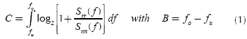
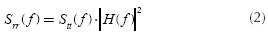
In order to be able to use (1), we must know the transmission-power density spectrum Stt(f), the channel's transfer function H(f) as well as the noise-power density spectrum Snn(f) at the receiver. If a channel is linear and time invariant (LTI), the received signal-power density spectrum, Srr(f), (using the Wiener-Kintchine theorem) is (Shanmugam, 1985):
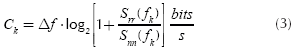
The frequency response of the channel can be separated into N narrow band flat fading sub-channels of span Δf= B/N (Langfeld, 2001). If k =1..N, the received power of the k subchannel is P(fk) = Srr (fk) .Δf. The capacity of each sub-channel k is:
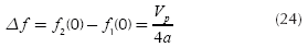
so, using (2) and (3), the total channel capacity is found:
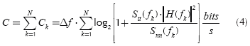
The importance of finding an expression for channel transfer function is evident in (4). So, the following lines are devoted to find it.
If the received signal in a telecommunications system, y(t), is the result of a sum of M multipath signals caused by a signal x(t) at input of the channel, y(t) can be expressed as:
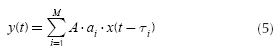
where A is the maximum amplitude of the signal at input of channel, αi. is the attenuation caused by the channel to the multipath signal i, τi. is the delay of the multipath signal i and M is the total number of multipath signals. A more useful expression of the Equation (5) is:
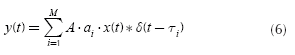
If the definition of convolution integral is applied to the Equation (6), this equation becomes:
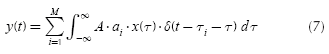
Because an LTI system is considered, and applying specifically the linear property, y(t) can be expressed as:
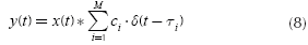
with ci = A · a. If h(t) is defined as:
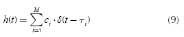
then (using the Fourier Transform) the transfer function H(f) is,
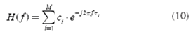
This general result is stated in (Dostert, 2001; Ferreira, Lampe, Newbury & Swart, 2010).
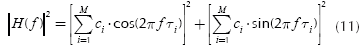
From Equation (10), it is possible to obtain |H(f)|2 in order to develop the Equation (4):
Now some conditions are assumed to build the theoretical model (and a boundary). Assuming that all тi's are equal to a time T, then:
and replacing (12) into (11) yields,
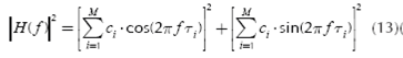
The two sums of (13) are equal if:
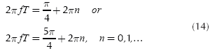
and simplifying,
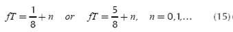
With these considerations, (13) becomes (with cos (2Π fT ) = √ 2/2):
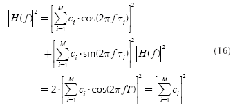
If additionally all c' sare equal, then,
and replacing (17) in (16) is obtained,
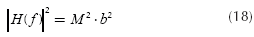
Equation (18) shows with great simplicity the influence of physical parameters (M echoes) and electrically (attenuation b) in the magnitude squared of the channel transfer function, indicating that this function increases with the square of the number of echoes, matter that is noteworthy. Equation (18) updates the Equation (4) as follows:
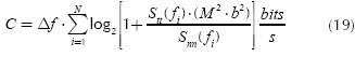
Equation (19) shows that it is possible to keep constant the capacity if the product between Stt (f) and M is modified adequately. If M is increased it is possible to decrease Stt (f).
Approach to an implementation of the theoretical model of the multipath channel
At this point, could emerge, in a natural way, the question What would be the scenario to assume the value |H(f)|2 described by Equation (18)? To answer this question, a simplified elliptical geometric model (Ma & Patzold, 2007; Patzold M., 2012, section 8.4; Patzold & Hogstad, 2006), is used.
An optical principle states that if a ray strikes a flat surface, it is reflected such that the angle of incidence equals the angle of reflection, which is true for an electromagnetic wave that strikes a perfect conductor. When a ray strikes an ellipsoid, it is possible to assume that it is reflected against the tangent plane at the point where it clashes. If the ray in question emanates from a focus of the ellipsoid, it reflects in the direction of another focus (De Oteyza, Lam, Hernández, Carrillo, & Ramírez, 2005), as it is shown in Figure 1.
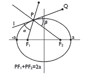
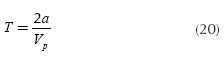
As the propagation path for any ray has a length of 2a, then the time of each ray to get from one focus to another (considering the phase velocity Vp constant for the entire scenario, and TX and RX are at the focuses) is:
To simplify the model, it is considered in the first instance that V is independent of frequency. In other words, a non-dispersive mode is considered (a full discussion of this aspect is found in Pierce, 1974). In a second case studied, it is considered the dispersive mode, in which case Vp =2Πf / β, with β being equal to phase constant.
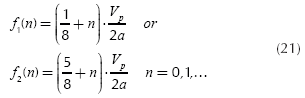
Applying Equation (20) to Equation (15) it can be obtained the frequencies that would make the capacity depends directly on the number of echoes:
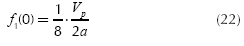
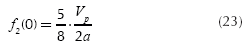
Now it can be calculated some of these frequencies:
if n = 0:
In general, the set of frequencies can be expressed as,
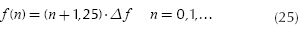
If N carriers are transmitted the capacity is obtained from (19):
Equation (26) shows the theoretical capacity of a channel whose structure is ellipsoid, which by nature has a multipath propagation. The dependence of the capacity with the number of reflections M and with Stt(f (n)) shows a possible exchange mechanism between M and Stt(f (n))in order to maintain this capacity constant.
Capacity of a channel with a single point of reflection
In this section, the capacity of a channel with a single reflection point is shown; in contrast with the above case where there are multiple channel reflections. In principle, it is not clear that a single point of reflection can produce a marked influence on the capacity and the creation of exchange mechanisms. To explore these aspects, a transmission line is studied, whose structure is shown in Figure 2.
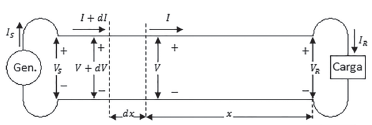
If l is the length of the line, the voltage equation as a function of the length is:

where γ is the propagation constant and it is equal to:
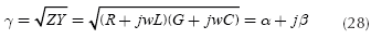
The real part, α indicates the attenuation suffered by the voltage waveform and β, which is the imaginary part indicates the rate of change of phase of the wave as it propagates. The electrical parameters of the transmission line per unit length are:
R: serial resistance per unit length
L: serial inductance per unit length
G: shunt conductance per unit length
C: shunt capacitance per unit length
The reflection coefficient is defined as:
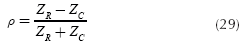
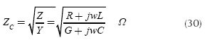
being Zc the characteristic impedance, which summarizes the basic parameters R, L, G and C as well:
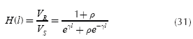
Combining Equations (27) to (30) can be obtained:
At this point is important to remember the concept of negative feedback (Imperial College London, 2015), whose block diagram is shown in Figure 3.
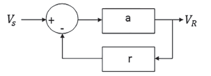
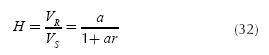
It is not difficult to find Equation (32), which describes the circuit of Figure 3:
If α y r are positive, there is not a risk that the transfer function will have a singularity. Equation (31) can be written using the form of Equation (32) as follows:
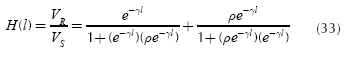
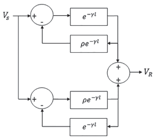
Equation (33) is represented in Figure 4.
Source: Author
Figure 4 Representation of a transmission line as a combination of circuits with negative feedback.
Figure 4 shows that there is a direct influence of the reflection coefficient, ρ, in the path between transmitter and receiver, as in reverse.
Of particular interest is the transmission line of length λ/4 (λ = wavelength). If α = 0 (as a first approximation) and l= λ /4, then:
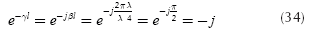
If this result is applied to Equation (33) yields:
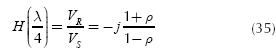
therefore,
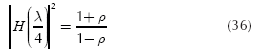
If ρ = 1 (terminated line in open circuit) clearly there is a stability problem in Equation (36). However, in actual transmission lines a can be small but not zero, therefore these transmission lines have not some stability problem; however, |H(f )| may has large values.
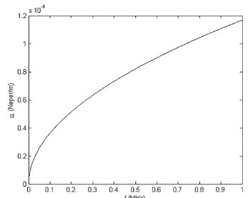
As a case study, the calculations for a copper bifilar line with polyethylene insulation at frequencies up to 1 MHz, is performed, taking data and calculation methods proposed by Neri in Chapter 1 of his book (Neri, 2004). In Figure 5 is shown the result of the calculation of a for a transmission line of length λ / 4.
To analyze the case α≠0 and l = λ / 4, the following term is defined:
and using this definition and (34):
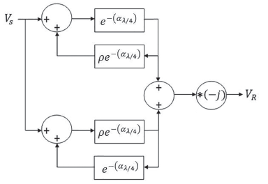
Replacing Equation (38) into Equation (33) yields:
Equation (39) can be represented in a block diagram as shown in Figure 10. It is noted here that feedbacks are positive and the output is reactive.
Source: Author
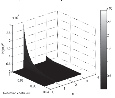
Figure 8 |H(n λ / 4 )|2 as a function of n and the reflection coefficient for a bifilar line at a frequency of 1 MHz.
Source: Author
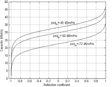
Figure 9 Capacity of a channel composed by bifilar lines of length nλi/ 4 with n = 1.
Source: Author
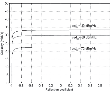
Figure 10 Capacity of a channel composed by bifilar lines of length nλi/ 4 with n = 2.
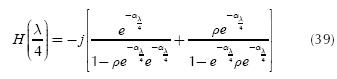
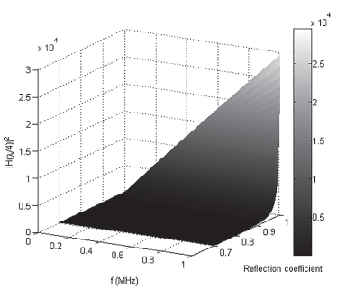
Of particular interest is to find |H(λ / 4 )|2 using Equation (39):
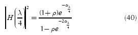
|H(λ / 4 )|2 can be plotted as a function of the frequency and the reflection coefficient and as is shown in Figure 7. In this graph, there are frequencies up to 1 MHz and reflection coefficients from 0,7 to 1 (characteristic impedance is real in this case). It is seen that both the higher the frequency and greater the reflection coefficient, significant values of |H(λ / 4 )|2 can be obtained. As a result, |H(λ / 4 )|2 (and consequently the capacity) can be controlled via the reflection coefficient.
This behavior shows that the greater is the attenuation (which increases with frequency, as shown in Figure 5) greater the control over the value of |H(λ / 4 )|2 with p as the control variable.
The above calculations were made for a line λ / 4 . Now considerations are made for lines of length n λ / 4. If n λ / 4, and following procedures similar to those shown can be found:
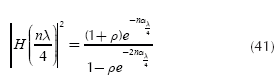
It is important to investigate the behavior of | H(n λ / 4 )|2 against n. Specifically, this behavior is studied at a frequency of 1 MHz, which is shown in Figure 8.
In Figure 8 remarkable peaks of |H(n λ / 4 )|2 are observed for values n = 1,3... or in other manner for line lengths λ / 4, 3 λ / 4... In general for n odd, significant values of |H(n λ / 4 )|2 will occur. It can be concluded that the line length is a factor to achieve peaks of |H(n λ / 4 )|2.
At this point it is possible to state an exchange between transmitting power and a reflection environment in relation to channel capacity. For calculation of capacity, values used by Dr. Walter Chen (1998) in his research about DSL are taken, in order to configure a communications scenario. Therefore power spectral density of the transmitted signal (psdtx) is equal to -40 dBm/Hz and the power spectral density of the white noise is equal to -140 dBm/Hz. The channel capacity is calculated with Δf = 1500 Hz, f up to 1 MHz and N = 627 and using the following equation:
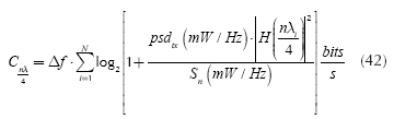
In Figure 9 is clearly seen the interchange between the PSD and the reflection coefficient in relation to the capacity. This calculation was made for the bifilar line that has been studied and a length n λ/4 (with n = 1, odd). It is noted that a capacity C=30 M bit/s can be obtained with a psdtx = -40 dBm/Hz and a reflection coefficient=- 0,5052 or with a psdtx = -50 dBm/Hz and a reflection coefficient = - 0,0225 or with a psdtx =-72 dBm/ Hz and a reflection coefficient=- 0,8771. Therefore, the interchange is shown.
In Figure 10 the same calculations are done for n = 2, but the interchange between psdtx and the reflection coefficient is narrower for intermediate reflection coefficients than the former case (see Figure 9).
Conclusions
In this paper has been shown that with SISO or MISO channels, the capacity of the channel can be varied depending of its physical structure and the electric environment of propagation. On the other hand, the capacity can be conserved controlling nicely the number of reflections (case of elliptical cannel, controlling by means of the product Stt (f(n)) . M2) or the reflection coefficient (case of multiple transmission lines forming a MISO cannel, controlling by means of the product psd(tx -|H(n λi / 4 )|2). These results are a consequence of the use the physical and electrical characteristics of channel unlike the standard Shannon treatment.

