


 English (pdf)
 Article in xml format
 Article references
 Send this article by e-mail
 Cited by SciELO
  Cited by Google
  Similars in
SciELO
Similars in
SciELO  Similars in Google
 Permalink
Introduction
Control of a system plays a key role in the performance of the entire system. The appropriate control parameters selection for obtaining the desired results is a cumbersome task.
Finding the optimal PI control parameters has always been a difficult task. The conventional method to obtain PI control parameters is by trial and error method which requires user's intuition and experience.
There are some algorithms in vogue for the estimation of PI parameters (Kumar, Kumar, & Tyagi, 2016). The fuzzy nature critic-based learning algorithm (Khorramabadi & Bakhshai, 2015), Simplex (Aniruddha M. Gole, Filizadeh, Menzies, & Wilson, 2005) and PSO algorithms (BÄ°NgÃœL & Karahan, 2012; Chen, Li, & Zhou, 2012; Gahramani, Lak, Farsadi, & Hosseini, 2013) are prominent among them. Simplex and PSO algorithms usually work on the principle of convergence of objective function. Generally in HVDC system, these algorithms are implemented by constructing an equation of objective function after considering the transfer functions of all control units and power devices in a system including PI control, rectifier/inverter, DC line, and measurement units. The main drawbacks of this method are: 1) it brings the inaccuracy due to approximations taken during the building of the equations of objective function and the representation of the system; 2) it faces many difficulties in complex network caused by intricate calculations of objective function.
In this paper, the two techniques i.e. the evaluation of objective function using transient simulation (A. M. Gole, Filizadeh, Menzies, & Wilson, 2003; Aniruddha M. Gole et al., 2005; Filizadeh, Gole, Woodford, & Irwin, 2007; Woodford, Gole, & Menzies, 1983) and the convergence of objective function using particle swarm optimization (PSO) algorithm (Eberhart & Kennedy, 1995; Van den Bergh & Engelbrecht, 2006; Zhang & Liu, 2012), are merged into single application in PSCAD by taking accurate results from simulation to design precise and user-friendly toolbox for finding PI parameters in PSCAD (Center, 1998). The advantages of this toolbox are: 1) no requirement to determine the model of each individual element for evaluating the objective function, instead simulation network is used for evaluating the objective function. The detailed models of the power system and control system in electromagnetic transient software, such as PSCAD are used to evaluate the objective function, which avoids the inaccuracy that can be caused by approximations as mentioned above. 2) No experience is required to find PI parameters as opposed to trial and error method or simplex method that has difficulty in selecting initialization of PI parameters. 3) Multiple PI controllers are optimized simultaneously by only considering a single parameter for generating the objective function i.e. variation in current. The optimization program is linked in loop with power system model in PSCAD, which can automatically find out the proper control parameters without any requirement of initial values.
This paper is distributed in the following sections: Section II discusses PSO algorithm and its parameters selection, PSO simulation representation in terms of flow chart and the evaluation of integral square error (ISE) objective function using transient simulation. Section III displays the experimental results. Section IV presents the conclusions of this paper. Multi-infeed LCC HVDC network is used to verify the functionality of the toolbox.
Self-Generated PI Control Parameters Technique
The Brief Introduction of PSO
PSO algorithm was proposed as Swarm Intelligence Algorithm by Dr. Kennedy and Eberhart in 1995 (Eberhart & Kennedy, 1995). Every particle tries to reach its best solution during iteration process by dynamically changing and adjusting its position and velocity.
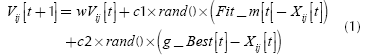
Where, 'Fit_m' is the local best solution; it is the optimized best solution of the particle itself by its own experience and results. 'g_Best' is the best solution of particle by its own experience and also the others experience. 'X/ is i-th particle of swarm and it is adjusted by velocity 'V/. The velocity depends on the particle position from its own local solution and also its neighborhood best solution. 'rand()' generates random numbers between 0 and 1. 'c1' and 'c2' are acceleration coefficients. 'w' is the inertia weight.
PSO is very sensitive especially in selecting acceleration coefficient c, inertia weight w and velocity V. If the initializations of these parameters are wrong, then it may leads to divergent or cyclic behavior (Van den Bergh & Engelbrecht, 2006). There are initial values of inertia weight 'w = 0,7298' and acceleration coefficient 'c = 1,49618' defined by Eberhat and Shi (Shi & Eberhart, 1998), which are considered as good parameters that leads to convergent trajectories.
The Flowchart of Proposed Technique
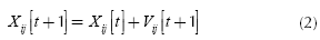
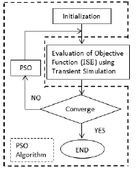
The flowchart of simulation based PSO algorithm implemented in PSCAD is shown in Figure 1.
The advantages of using PSO technique over others are that it is a derivative-free algorithm, less sensitive to the objective function's nature, easy to implement and it does not confine to local region, rather it has an ability to escape local minima to find optimal solution (AlRashidi & El-Hawary, 2009; BÄ°NgÃœL & Karahan, 2012; Gahramani et al., 2013). The initialization of control parameters in PSO is not required by user unlike Simplex algorithm (Zhao, Lu, & Li, 2007). Instead, it makes a self-array of random values of control parameter and uses this array to generate next optimal array by using PSO technique.
The values selected for the numbers of population (Pop) and the numbers of iteration (Iter) are 10 and 6, respectively. These values are selected to minimize the number of simulations required to get optimal results, without sacrificing the accuracy of outcome. Following representations are used in the flow chart: 1) 'SimRun' the number of simulation runs, 2) 'X(Pop)', 'X_U(Pop)', and 'XE(Pop)' the array of random numbers, array of PSO updated numbers, and the array of the best parameters among 'X(Pop)' and 'X_U(Pop)', respectively. 3) 'Fit(i)', 'Fit_U(i)', and 'Fit_E(i)' the array of the fitness value from 'X(Pop)', 'XU(Pop)', and the best fitness values among 'Fit(i)' and 'Fit_U(i)' respectively, 4) 'Fit_m' is the minimum fitness value or the local best fitness value, Fitmeq is the minimum fitness value of Fit_E(i) , and g_Best is the global best fitness value, and 5) g_X is an array of 'X' vertices of g_Best.
PSO itself initiates control parameters by generating array (same as population) of random numbers X(Pop). The fitness values 'Fit(i)' of the objective function for each 'X' is evaluated from the simulation results. The current error 'ΔI' is obtained from the HVDC simulation result as well, which is used as input to ISE objective function; that is an additional design in an actual simulation for finding fitness value. The position and velocity of an array X(Pop) update and a new array X_U(Pop) is formed by PSO. Fitness values for X_U(Pop) are produce again iteratively through simulation.
PSO algorithm has been used in different applications of power systems optimization (Gaing, 2004; Liu & Hsu, 2012; Yoshida, Kawata, Fukuyama, Takayama, & Nakanishi, 2000).
The Objective Function
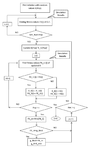
The transient simulation is used for evaluation of objective function in this paper. In this technique, the problem that cause instability in a system is pointed out and the objective function is designed by using simulation results of the system (Woodford et al., 1983). The Integral Square Error (ISE) is used as objective function in a system presented by (Aniruddha M. Gole et al., 2005; Filizadeh et al., 2007).
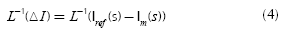
Where, the simulation run time is ts, at which the system is supposed to reach its steady state. To speed up multi-runs optimization, just reduce 'ts' to its minimum possible value within the steady state time of a system. The simulation run time 't = 0,8 sec' is set during PSO optimization. ΔI = Iref-Im is the current error, which is the difference of reference current Iref and measured current Im.
The current error ΔI is used in the objective function because the system's objective is to maintain current at Iref. So, minimizing ΔI to the lowest value (approaching to zero) fulfills the objective to optimize the control of HVDC system (Aniruddha M. Gole et al., 2005; Filizadeh et al., 2007).
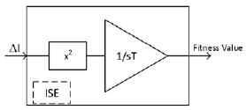
ISE is the integral of ΔI2 with respect to time ('0' to 'ts'). Square of current error ΔI2 provides the amplification. Also, it provides only positive values of fitness value that is convenient to visualize and to understand. The block diagram of ISE objective function is shown in Figure 2.
The interface of evaluating objective function by using transient simulation and the convergence of the objective function fitness value through PSO algorithm are shown in Figure 3 (A. M. Gole, Filizadeh, & Wilson, 2005).
The current control loop of the rectifier side including the PI control tuner such as P&O algorithm (Ortiz & Ramos-Paja, 2015) is shown in Figure 4. The current difference 'ΔI' is the input of the PI controller and the firing angle 'α' is its output, which is further controlling the rectifier of HVDC.
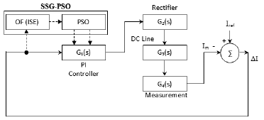
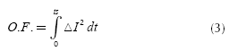
Where, G1(s) represents the transfer function of PI controller. G2(s), G3(s) and G4(s) represent the transfer function of rectifier/inverter converter, DC line, and the measuring unit of HVDC system respectively. The overall gain of rectifier/ inverter side of HVDC is given as G0(s) = - G1(s) G2(s) G3(s) G4(s).
There is,
In SSG-PSO parameter selection process, ΔI is the input to the proposed SSG-PSO toolbox. The PI control parameters are taken from its output during run-time of simulation. Multiple PI controllers are optimized simultaneously by offering them same parameters obtain from SSG-PSO. By doing so, the parameters are generated for both of them that give the overall best results.
The selection process of PI control parameters using PSO algorithm by minimizing the objective function in transient simulation is separated from the actual current control loop and its flow lines are represented by dotted line. It is not an actual part of HVDC control, but it is only used to find out PI control parameters. Once the parameters are obtained, this part must be disabled from the toolbox’s option for normal simulation of network. The convergence to fitness value of objective function by using SSG-PSO toolbox is shown in Figure 5
Experiments and Results
The simulation model of multi-infeed HVDC system that is interconnecting Central-East China Power system is under consideration in this research. The model is shown in Figure 6. The power rating of the multi-infeed HVDC systems are 3000 MW, 3000 MW and 1200 MW for first, second and third HVDC lines respectively. The operating voltage of the multi-infeed HVDC systems is ±500 kV.
The rated currents of three HVDC lines are 6000A, 6000A and 2400A, respectively. The transmission model at AC side is 'Π-section model', as shown in Figure 6.
The experiments are performed for the different simulation time intervals for generating optimal parameters and it is observed that SSG-PSO produces nearly consistent PI parameters. So, it is recommended that the run time should be set to the settling time of power system for finding optimal control parameters through SSGPSO. In this network, the run time is set to 0,8 sec to perform multiruns optimization. After nearly 40 runs of simulation, the objective function converges to its minimal fitness value. When the network is simulated from the control parameters that are generated from SSG-PSO toolbox, the rectifier and inverter AC power graphs of three lines are observed.
The three phases to ground fault is introduced on AC network near the rectifier side of the third line at 2 sec for duration of 0,04 sec (till 2,04 sec). The AC power is measured to observe the transient response of the HVDC control.
The initial and optimized PI control parameters, Kp and Ki, are given in Table I. These optimized parameters are considered as global control values (best values), and are thus implemented in PI controllers of multi-infeed HVDC converters.
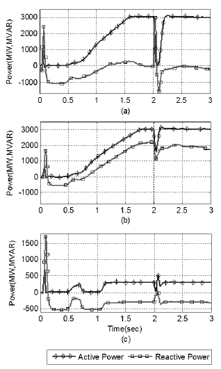
The responses of the rectifier side of all three lines against fault are shown in Figure 7, when the simulation is running with initial control parameters. The circles line represents active power 'P' and the squares line represents the reactive power 'Q'. The horizontal scale shows the simulation run time and the vertical scale shows the active power 'P' (MW) and reactive power 'Q' (MVAR).
Source: Authors
Figure 7 Initial waveform of active and reactive power: (a) First rectifier of multi-infeed HVDC systems; (b) Second rectifier; (c) Third rectifier. (Active power in (MW), Reactive power in (MVAR)).
Figure 7 is distributed in subfigures: a) the waveform of rectifier's active and reactive power (P and Q) for first line of multi-infeed HVDC systems, b) the waveform for second line, and c) the waveform for third line. In Figure 7(a), it can be seen that the active power 'P' is approaching to 3000MW at nearly 1,5 sec, while the reactive power 'Q' is reaching to zero at around 1,8 sec. The three phases to line fault is introduced on a system at time 2 sec, the variation in P and Q can be seen in Figure 7. In Figure 7(b), the active power reaches its steady state at 1,7 sec and contributes 3000MW to multi-infeed HVDC systems, whereas third line is contributing the least active power of approximately 350MW to the network, but it reaches its steady state early at 1,1sec as shown in graph (c) of Figure 7.
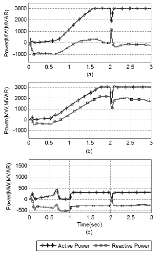
The rectifier side active power 'P' and reactive power 'Q' of all three lines for optimal value of PI parameters are shown in Figure 8. The improvement in the transient response can be seen in graphs. The power achieves its steady state value quickly and power drop has been reduced significantly. Also, the starting transient response of the system's rectifier power 'P' and 'Q' have been improved and magnitude of overshoots have been reduced.
Source: Authors
Figure 8 Optimized (SSG-PSO) waveform of active and reactive power: (a) First rectifier of multi-infeed HVDC systems; (b) Second rectifier; (c) Third rectifier.
Source: Authors
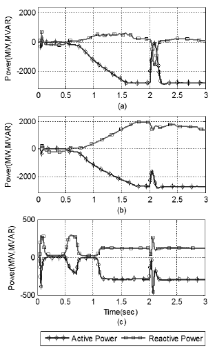
Figure 9 Initial waveform of active and reactive power: (a) First inverter of multi-infeed HVDC systems; (b) Second inverter; (c) Third inverter. The fault is introducing at time 2sec.
The AC side active power 'P' and the reactive power 'Q' of inverter side of all three lines are shown in Figure 9, when the system is simulated from the initial control parameters. The negative sign of inverter power 'P' in Figure 9 shows that the power is being consumed by the load at inverter side and the power is going out from HVDC network to AC side.
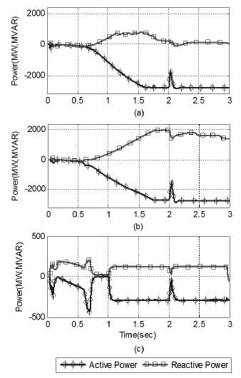
The active and reactive power 'P' and 'Q' of inverter side for all three lines are shown in Figure 10, where the new PI control parameters are set. The improvement in stabilizing time and power drop against fault can be seen in Figure 10 as compared to Figure 9 (result produced from initial control parameters).
Conclusions
The optimized online self-generated control parameter toolbox is designed and implemented to enhance the performance of Multi-infeed HVDC systems. The objective function is evaluated through transient simulation, thus the solution of EMTDC simulation directly estimates the objective function. Therefore, altering in a model doesn't require new calculation. The control parameters of multiple PI controllers are obtained simultaneously through it. The PI control parameters are self-generated from 'SSG-PSO toolbox' in less than 40 runs of simulation. Moreover, it is observed that the acquisition time for objective function during steady state of a system has not effect in the generation of new parameters. The PI control parameters generated by SSG-PSO toolbox remained nearly same for the objective function evaluation at 0,8 and 2 sec respectively, So, the objective function acquisition time can be set to the minimum possible time to steady state of a system to speed up the optimization process.
The results obtained after using the new PI control parameters are very satisfactory and the performance is significantly improved. The time to steady state and overshoots are improved when the system is simulated with the SSG-PSO toolbox generated PI control parameters. It is confirmed by comparison of power graphs presented from Figure 7 to Figure 10 of Multi-infeed HVDC system by operating a system with initial and optimized PI control parameters. System has become more resilient. During fault, the power drop using new PI control parameters is less as compared to initial PI control parameters. It is concluded that SSG-PSO is user-friendly and parameters generated from SSG-PSO toolbox markedly improve the transient performance of a system.

