


 English (pdf)
 Article in xml format
 Article references
 Send this article by e-mail
 Cited by SciELO
  Cited by Google
  Similars in
SciELO
Similars in
SciELO  Similars in Google
 Permalink
Introduction
The most used mechanical element to transmit power and movement is a shaft. They are used in all kind of industrial systems. During operation they can suffer deflections. In order to increase their life cycle, shaft straightening reparations are needed. The main parameter for straightening machines is the maximum force that can be applied in the process. It is important to know the mechanics of the straightening process; some studies used experimental data (Schleinzer, et al., 2001; Srimani, et al., 2005) and numerical models (Jing, et al. 2013; Wu, et al., 2000). Some authors have studied the process and how to control the stages based on material response (Li, et al., 1999; Seung-Cheol, et al., 2002). An important phenomenon is the residual stress (Schleinzer, et al., 2001) and the springback of the material. In many cases they studied the effect on test bars and rails. The idea with this work is to develop a model based on the elasto-plastic behavior of the material and the geometric characteristics of the bent shaft. This will be an important tool for design straightening machines, and also to improve reparation processes.
Proposed model
In order to develop a mathematical model of a bent shaft deformation based on geometry and mechanical behavior of materials, some assumptions have to be made. The final goal is to compute the force necessary to straighten a bent shaft.
First, the bending moment required to straighten the shaft will be computed with Equation (1) (Ugural, and Kenster, 1995).
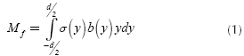
Where, y is the height of the cross section, b is the width, d is the diameter and o is the normal stress. Figure 1
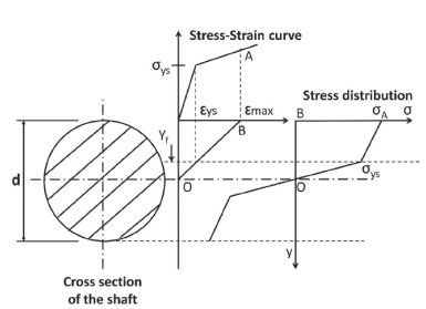
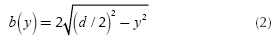
In this case the cross section is circular, it can be shown that the width of the section in terms of height is given by Equation (2).
The normal stress, as a function of height, is a piecewise continuous and bounded function. The fact that it is a continuous piecewise function is due to the transition from elastic flow, determined by Hooke's law, to plastic flow which can be approximated by the Ludwik equation (Lubliner, 2008); and it is bounded by 0 (no stress applied) and sut (ultimate strength). Then, the normal stress as a function of height is given by:
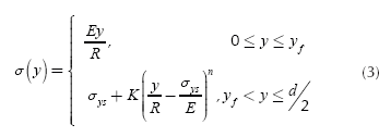
Where E is the Young modulus of the material, R is the average radius of curvature of the shaft in the cross-section analyzed (Where R ≠ ∞ due to shaft deflection), σys is the yield strength of the material, K is the strain hardening coefficient of the material, n is the strain hardening exponent of the material and yf is the height which divides the elastic and plastic region in the cross section.
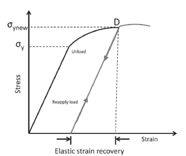
On the other hand, once the shaft is deformed plastically, the stress-strain curve changes (Strain hardening - Cold work) and the new function σ'(y) has to be computed. The material tries to recover its original shape (This phenomenon is called "springback"). This recovery is approximately linear with a slope equal to the Young modulus of the material. Also the material suffers a strain hardening due to plastic deformation and the new yield stress σ'ys is equal to the strain that caused the deformation observed in the component. Figure 2 shows this process.
Then, considering the new stress-strain curve, the new normal stress function σ' is given by:
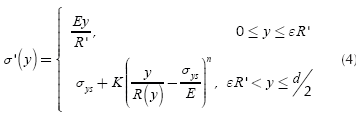
Where R' is the radius of curvature after deformation with stress level σ 'ys and the load still applied, e is the strain corresponding to σ'ys and R(y) is the radius of curvature of the shaft at height y. This latter term is also dependent on the variation of the stress σ' but this is a function of y, then R ends a function of y.
Now, the values of R' and ε have to be computed. The strain ε is determined using equation (5).
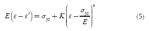
Where ε' is the strain corresponding to the springback, and in this case it is given by:
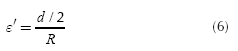
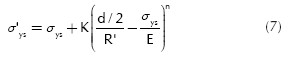
Now R' can be calculated using Equation (7).
The stress corresponding to R(y) = ∞ is denoted by σ1 It is important to take into account the material springback again, so an extra stress (overbending) has to be added, this extra stress is denoted by σ2Figure 3 illustrates both stresses.
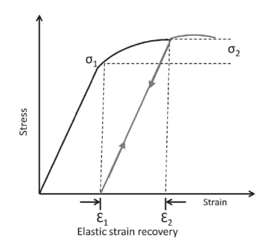
Given that elastic strain recovery is approximately linear with a slope equal to the Young's modulus and ε1 is the strain corresponding to R = ∞, then:
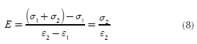
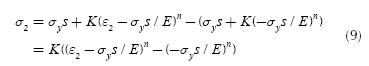
Where ε2 can be obtained from Ludwik equation:
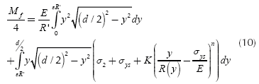
Taking advantage of the symmetry for stress distribution and width of the cross section the equation for the bending moment Mf is given by:
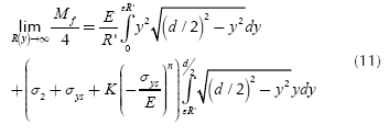
The goal is to know the bending moment Mf when R(y) approaches infinity. The integral is a Riemann series evaluated over a range in which the function to be integrated is uniformly continuous, then:
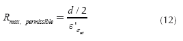
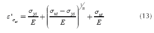
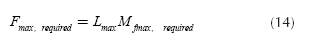
For the design of straightening machines is imperative to know the maximum force required to straighten a shaft. In order to compute the maximum force is necessary to define the maximum diameter dmax, the maximum length of the shaft Lmax and the maximum radius of curvature Rmax. The latter can be calculated as follows using Equation (12) and Equation (13):
Finally, the maximum force required for a straightening process (this is the force the machine has to applied to the shaft) is given by:
Results and discussion
To validate the model a case was selected. The material is the AISI 4340 steel. The stress-strain curve for this material is presented in the Atlas of Stress-Strain Curves (Atlas of Stress-Strain Curves, 2002). To determine the strain hardening coefficient K and the strain hardening exponent n for this steel a linear regression was used:
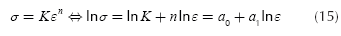
Where, a0 and a1 are the unknown coefficients for the linear regression. Table 1 shows the data used in the regression.
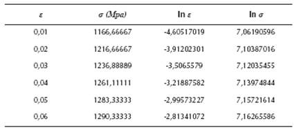
The results for K and n are 1515,55 MPa and 0,0567871, respectively. Table 2 resumes all data used.
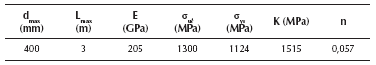
Finally, the maximum force required for this case is 11767 kN (1200Ton). This force is in the range of power of the machines designed for this size (1000-3000Ton).
Conclusions
A mathematical model was developed for straightening process of a bent shaft based on material behavior and geometric characteristics. The model uses the elasto-plastic mechanics of deformation. The model was validated with AISI 4340 steel which is a material highly used in machine elements. The maximum force calculated for this case is in the range of the applications for the geometric and material characteristics. This model is an important tool for design new straightening machines, and also to develop better reparation and maintenance techniques and processes. Future work should focus in more experimental data in order to adjust the model.

