


 Inglês (pdf)
 Artigo em XML
 Referências do artigo
 Enviar este artigo por email
 Citado por SciELO
  Citado por Google
  Similares em
SciELO
Similares em
SciELO  Similares em Google
 Permalink
Introduction
In recent years, the use of Brushless DC Motors in automotive, medical, robotics, aerospace, and automation applications has been increasing, due to performance improvements such as efficiency, torque speed ratio, dynamics response, and speed ranges (Gieras, 2002; Krause, Wasynczuk, & Sudhoff, 2002).
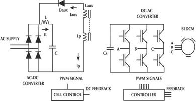
The electronic switching waveforms needed to supply the BLDCM windings of a traditional driver requires the use of an energy conversion from AC to DC and DC to AC to generate the correct sequence (Xia, 2012), including the position of the rotor via sensor or sensorless techniques (Bist & Singh, 2014c; Gamazo-Real, Vázquez-Sánchez, & Gómez-Gil, 2010; Kim, Lee, & Ehsani, 2005). From a power quality perspective, the AC-DC-AC traditional converter shown in Figure 1 generates a high harmonic content due to the way the driver demands current from the power supply, resulting in poor power factor (Singh & Singh, S., 2010).

By considering this problem, the energy conversion process is modified by introducing an intermediate stage of DC-DC conversion, typically a boost-based converter (Pereira, Da Silva, Silva, & Tofoli, 2015), which improves power factor and reduces harmonic content, as shown in Figure 2. When speed control is performed directly in the DC-AC conversion stage in a traditional driver, switching losses are generated due to the efforts of the semiconductor switches (Yen-Shin, Fu-San, & Yung-Hsin, 2004). The inclusion of an intermediate stage not only helps improve power factor but also allows control of BLDCM speed, which results in reduced switching losses since the DC-AC converter operates at the fundamental frequency.
The BLDCM drivers that offer power factor improvements can be categorized as non-isolated PFC (Power Factor Correction), isolated PFC, bridgeless non-isolated PFC, bridgeless isolated PFC, and high-quality rectifiers (Singh, 2014; Singh & Bist, 2013).
For non-isolated PFC BLDCM drivers, literature has reported several proposals of intermediate stages with particular characteristics. By 2016, an analysis of SEPIC and CUK was presented (Crisbin & Sasikumar, 2016), all of them operating in DCM (Discontinuous Conduction Mode). In 2014, an alternative was presented by using a canonical switching cell operating in CCM (Continuous Conduction Mode) and DCM (Bist & Singh, 2014a). The aforementioned BLDCM drivers achieve unitary power factor due to their voltage follower behavior and are in compliance with the IEC 61000-3-2 standard ("Limits for harmonic current emissions (equipment input current <16 A per phase)," 2000), with a minimum of components. However, these do not provide galvanic isolation.
In the case of the isolated PFC BLDCM driver category, literature has reported the following DC-DC intermediate stages. The first alternative uses a Sheppard-Taylor converter with a triple-DCM; the converter consists of a single transformer, two switches (two PWM control signals), an inductor, two capacitors, and four diodes (Singh & Bist, 2015). The second alternative uses a boost-forward single-stage isolated power-factor-corrected power supply (SSIPP); the isolated cell converter has a transformer with two primary windings connected in parallel, a single switch, two inductors, two capacitors, and five diodes (Bist & Singh, 2014b). Both drivers comply with the IEC 61000 3-2 standard and achieve unity power factor. Thus, the evaluation of each alternative depends on the application requirements in relation to power factor improvement or correction, the number of components involved at the DC-DC intermediate stage, and the galvanic isolation.
This paper presents an alternative for power factor improvement of a traditional BLDCM driver, by the inclusion of a single-sensor isolated DC-DC converter operating in discontinuous conduction mode. The main advantage, in comparison with other isolated PFC alternatives, is the compromise between the number of components (sensors, passive, and active components) and the power factor improvement.
Proposed converter and operating modes
Figure 3 shows the proposed intermediate stage, which incorporates an auxiliary winding interconnected to the primary winding of a high-frequency transformer, to provide feedback of recycled power into the input converter to shape the current demanded by the DC-AC stage. This operating mode is a function of the polarization of the auxiliary diode (D aux ).

The proposed converter presents three operation modes that depend on the commutation of the main switch (S 1 ).
Figure 4 shows the first operating mode, in which the main switch is turned off, the input inductor (L) is completely discharged and the secondary inductor of the transformer (L s ) discharges energy through the output capacitor (C s ). At this moment, the current (i j is equal to zero, and the input inductor current (i L ) demands energy from the power supply.

Analyzing the circuit in steady state, while the main switch condition is turned-off, the demand from the power supply takes a triangular shape with a width equal to the product of the input voltage (V AC ) and the input inductor current, so it is possible to set the input power (1) as

Where (2) expressed the off-time given by
Replacing (2) in (1), the input power (3) is equal to

From (3), it is possible to infer that, if the input inductor current is constant for each instant of time, the power waveform will depend on the input voltage and the DC bus voltage (V C ).
Figure 5 shows the second operating mode, in which the main switch remains in a turned-off condition; the energy in the input inductor is totally discharged, and the converter does not demand energy from the power supply.
The power factor improvement is largely due to the amount of energy returned to the input through the auxiliary winding interconnected to the primary winding of the transformer.
The final operating mode is shown in Figure 6; the main switch changes to a turned-on condition. The result is an energy charge into the input inductor and the primary inductor (L p ) of the transformer. For this instance, the input inductor current is equal to the auxiliary current; at this time, the converter does not demand energy from the power supply.

Theoretical design
Establishing in (4) a relationship between the number of turns and voltage in the primary and auxiliary windings (N
p
,N
aux
, V
p
,V
aux
) during the  condition.
Assuming that the primary voltage is equal to the DC-link voltage in the capacitor (C). Solving for the auxiliary voltage, the transformation ratio (n) is represented in (5) as
Duty cycle for DCM
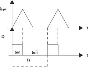
The peak current of the input inductor (i Lon-pk ) for on-time is defined in (6) as follows

Therefore, the average current (i Lon ) in (7) is expressed as

Considering that the peak current in the input inductor has a triangular geometry as shown in Figure 7, the average current in (8) is
Performing the same analysis, but now for off-time for the second operating stage, the current peak of the input inductor (i Loff _ pk ) is obtained in (9)

Then in (10), the average current of the input inductor (iLoff)
Replacing (9) into (10) and solving the expression, the average current during off-time is obtained in (11)
As the peak current in the input inductor is the same for on-time and off-time in (6) and (9), then in (12) the equality is defined as

Solving for duty cycle at off-time in (13)
In (14) is defined the condition to ensure discontinuity in the input inductor
Replacing duty cycle at off-time, and solving in (15) for duty cycle at on-time
Energy balance
Figure 8 shows the power flowchart. The amount of recycled energy ( ) in half cycle of AC supply is defined in (1 6) as
And the input power in (17) is given by
Substituting (11) into (17) and solving in (18)

From the energy balance, in (19) the percentage of recycled energy (K), is defi ned by

Substituting and solving in (20) for the percentage of recycled energy

Applying an energy balance in the high-frequency transformer, the expression (21) for the primary winding of the proposed converter is a function of the output power (P o ), and the switching period (T S ) given by

Thus, the auxiliary winding (22) is

Considering the time in which the input power is equal to the output power and solving for the duty cycle at (23)
Substituting the duty cycle in the inequality that ensures current discontinuity and solving in (24) for the input inductor
Design procedure
The proposed design procedure is summarized in the following steps:
Defining the maximum duty cycle to ensure the discontinuous operating mode in the input inductor and the high frequency transformer
Finding the value of the input inductor by performing an energy balance
Establishing the amount of recycled energy returned to the power input
Calculating the secondary winding of the high frequency transformer, as a function of the desired output power
Calculating the auxiliary and primary windings
Experimental results
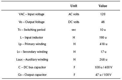
The proposed design procedure was implemented in an experimental prototype drive for a brushless motor model BLM-N23-50-1000-B; Table 1 presents the BLDCM specifications.
The implementation was conducted according to the design procedure of section 4; Table 2 shows the resulting design values.
An important step is to define the maximum duty cycle at rated power, in this specific case, a 31% of the duty cycle is the maximum value to keep the DCM in the input inductor as shown in Figure 9. If duty cycle exceeds this value, the discontinuous mode becomes continuous mode and changes the converter behavior.

Source: Authors
Figure 9 DCM operation mode; (a) Discontinuous current of the input inductor; (b) PWM signal control at 31 %.
Figure 10 shows the discontinuous transformer current of the primary, secondary, and auxiliary windings at a frequency of 100 KHz and duty cycle of 31%.

Source: Authors
Figure 10 High-frequency DCM current waveforms of the proposed transformer; (a) Primary winding; (b) Secondary winding; (c) Auxiliary winding.
The duty cycle is also related to the output voltage of the proposed converter, at 31%, the output voltage is equal to 48 VDC that supplies the DC-AC converter. Figure 11 shows the parameters associated with the performance evaluation of the BLDC driver such as speed, BLDC voltage and current per phase, and phase control signal based on six-step or 120 degrees technique. The dynamic response takes approximately 0.06 Seconds to stabilize the speed RPMs, and the increase of the BLDC current verify the operation. A well-known advantage of using an intermediate DC-DC conversion is that the DC-AC converter is used only for electronic commutation, with a low switching frequency operation that reduces the switching losses. The control is based on a typical PWM with a double PI compensator and setpoint at 6000 RPMs.

Source: Authors
Figure 11 BLDC driver performance waveforms; (a) Rotor speed; (b) BLDC winding current; and (c) Phase control signal.
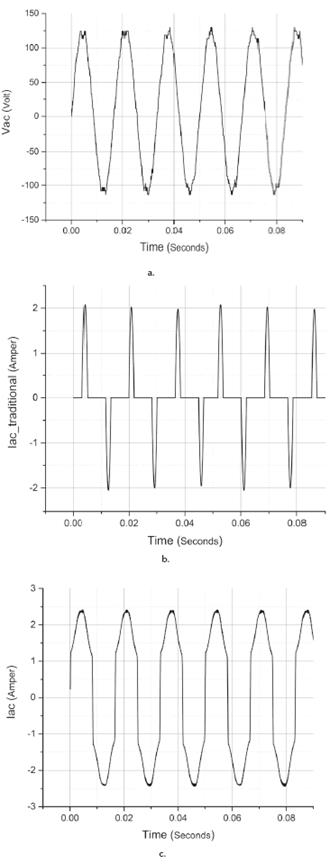
The implementation of the experimental prototype is based on a 3-phase DC-AC converter based on IGBT semiconductors. Figure 12 shows a comparison of AC input waveforms. The first waveform is the power supply voltage. The second waveform belongs to the proposed converter, where, although it does not present a unity power factor. It is significantly improved in 98% the power factor and 18% the harmonic content, and the third waveform draws the current demanded from the power supply by a traditional driver, which has a low power factor. Figure 13 shows a comparative bar graph of harmonic current and the standard IEC 61000-3-2 Class A, where it can be seen that the proposed converter meets the requirements.
Source: Authors
Figure 12 Comparison of AC input waveforms; (a) Power supply voltage; (b) Traditional driver current draw; and (c) Proposed driver current draw.

Source: Authors
Figure 13 Comparison of harmonic current limit; proposed BLDC converter and IEC 61000-3-2 Class A.
An important feature is that the speed control is a function of the DC output of the proposed isolated converter, this represents low losses in the IGBTs full-bridge due to fundamental switching; in comparison with a traditional and traditional PFC converters in which the DC bus is fixed and the speed control depend on the DC-AC converter directly. Table 3 shows an evaluation of features related to speed control regulation, 3-phase DC-AC inverter control, DC-DC converter control, BLDCM sensors, close loop DC-DC converter feedback sensor, DC-AC converter losses, power factor improvement, and galvanic isolation.

Table 4 presents a component number comparison of two isolated BLDC drivers versus the proposed converter. Herein, Sw is the number of switching controlled semiconductor, D is the number of diodes (high recovery and low-cost power diodes), L is the number of inductors, T is the number of high-frequency transformers, and C is the number of capacitors.

Finally, Figure 14 shows the experimental prototype of the proposed BLDC driver. The AC-DC converter used RM type cores for the construction of the input inductor and transformer, a single-ended PWM generator at 100 KHz, and an analog gate driver for the MOSFET semiconductor. The DC-AC converter has a single-phase AC-DC module to create a 24 VDC bus, in order to supply four DC-DC isolated step down of 24 to 15 VDC for the optocoupler stage used to drive the IGBT module and a microcontroller to embed a 120° technique for the switching sequence at fundamental frequency.

Conclusions
An isolated DC-DC converter for supplying the DC-AC in a BLDCM driver has been designed to improve the power factor at the power supply for low-power applications. BLDCM rotor speed is controlled by a single voltage sensor in the DC-link, which allows the DC-AC converter to operate at fundamental frequency reducing switching losses. Three operation modes in DCM have been explained and a design procedure has been proposed. Finally, the isolated DC-DC converter prototype has shown an acceptable performance with a power factor of 98%, a total harmonic distortion of 18%, and a reduced number of components in comparison with related work.

