


 Inglés (pdf)
 Articulo en XML
 Referencias del artículo
 Enviar articulo por email
 Citado por SciELO
  Citado por Google
  Similares en
SciELO
Similares en
SciELO  Similares en Google
 Permalink
Introduction
The excessive use of PE-based devices at the distribution as well as transmission level has seriously resulted in the deterioration of power quality. Low and medium power loads, such as variable speed drives (VSDs), uninterruptible power supplies (UPS), cell phone and computer chargers etc., draw non-sinusoidal and distorted current from the utility (Khadkikar, Chandra, & Singh, 2009). These current harmonics generate unwanted disturbances in the power system and compromise efficiency and stability of the network (Akagi, Watanabe, & Aredes, 2017). The simpler and cheaper technique for the removal of such harmonics is the use of passive filter, though it removes selective harmonics and requires retuning for the mitigation of others (Blanco et al., 2015). The problem is due to the resonance compensation characteristics for the fixed value of capacitance, inductance and their immense size (Ko, Swe, & Zeya, 2011). DSP programmable-gate-array-based systems were also introduced for the purpose (Thirumoorthi et al., 2012). Hybrid filters, the combination of both passive and active filters were also used, but these are too expensive to be implemented for harmonic elimination (Gupta et al., 2011). Thus, to overcome these problems, shunt active power filters (SAPF) were developed.
SAPF behaves as a harmonic current source for mitigation of harmonic currents that are drawn by non-linear PE-based loads. The purpose of the shunt filter is to inject current of the same amplitude, but opposite phase that cancels the harmonic currents oscillating in network (Sadati, Rahmani, & Saif, 2015). SAPF generally provide harmonic compensation, reactive power compensation and unbalance compensation (Carastro et al., 2008).
Recently, advanced techniques such as artificial intelligence (AI) are getting popularity due to its accuracy and effectiveness. Interconnected neurons manifest the response depending upon input stimulus. The input neurons translate the stimulus into decision as the output of network (Gomez et al., 2011). To take a decision, in a segment of iterative training, samples of data are used, and weights are adjusted until the desired results are obtained (Alarcon et al., 2014). Artificial neural network (ANN) uses algorithms, such as recurrent network and Hopfield, for an optimal operation (Greivulis, Levchenkov, & Gorobetz, 2008). Adaptive ANN-based compensation has also been used when weights are adjusted and computed online (Bhattacharya & Chakraborty, 2011). ANN adaptability is more rapid compared to traditional control schemes with high pass filters (HP) and PI controllers (Narayana, Kumar, & Rambabu, 2012). ANN can deploy with different approaches based on neural network intelligence, where minimum lose control technique is applied to permanent magnet synchronous motors (PMSMs) that increase the efficiency of the motor and decrease loses (Erdogan & Ozdemir, 2017).
In this paper, a three-phase SAPF with both PI and ANN controller is presented, employing conventional hysteresis and adaptive HBCC to address the power quality. Reference signals are calculated using IRP p-q theory. ANN is used to facilitate the extraction of compensating currents and its incorporation in the control structure of SAPF makes it more robust and dynamic.
Reference signal calculation
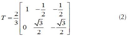
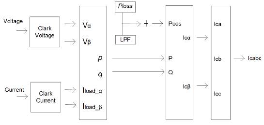
IRP p-q approach has been used for the reference current generation considering a balanced three-wire system. In IRP p-q theory, currents are calculated using the instantaneous powers in time domain. These currents can further be transformed into three-phase space vectors and two coordinates system by Clark transformation (Rajesh et al., 2016). For the balanced three-wire system, we can define the three-phase quantities as xa, x b and xc.
Where χ represent the line current or phase voltage and T is a constant.
In the equation below, u a and u b are the instantaneous voltage, and and the current phase vectors.
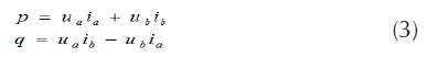
Using equation 3, instantaneous currents are defined as follow
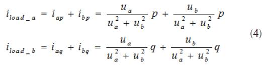
Figure 1 presents afore mentioned equations in block diagram.
Calculation of PWM signal
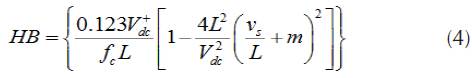
HBCC calculator varies the hysteresis band (HB) according to DC-link voltage (V dc ), slope of the current waveform and supply voltage (Vs). When the injected current tries to leave the limit of HB, an appropriate switch will work to ON and OFF states, so that the current remained in the limit of HB. Thus, HBCC self-adjusts the HB according to designed system. The performance of SAPF is enhanced by sustaining the modulation frequency to constant. HBCC is considered valuable in terms of stability, accuracy and very fast response (Rahman et al., 2017). HB is modulated to control the pattern for switching the inverter at various test points. All the three phases of band exhibit the same profile with the phase difference among them (Kale, & Ozdemir, 2005).
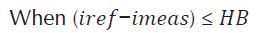
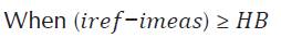
The appropriate working switches states are as follows:
First switch is at 1 (ON) and second switch at 0 (OFF)
First switch is at 0 (OFF) and second switch at 1 (ON)
The hysteresis band of HBCC defines the acceptable current error. Equation 5 shows that HB and switching or modulation frequency (fc) are inversely proportional and can be fixed to a constant value. The other controlling parameters are shown in their respective equation and m is the slope of current waveform.
The adaptive hysteresis calculation block is shown in Figure 2. HBCC controller generates the gating signals (g1) for the inverter, as shown in Figure 3.
Current estimation and loss signal
In this paper, DC voltage (Vdc) is identified and compared with the reference value and error difference known as (ia). It is amplified and added to the output of a filter, which in terms maintains the pure sinusoidal source waveform by adding the loss signal (Capelini et al., 2015). A PI controller is used instead of a PID because it is not possible to know the steady response with derivative function in this controller.
The general equation of working of the PI controller is as follows:
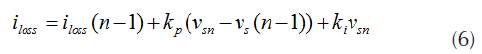
Where Kp and Ki are the constant gains of the PI controller. In this paper, PI controller is replaced with ANN since the values of Kp and Ki are tuned again for the varying loads that makes the system unreliable (Raju, & Reddy, 2014). In addition, the PI controller does not have the capability of improving the transient response of system. In contrast, ANN controller can extract data from noise, takes less development time, is suited for real world applications and has a fast response (Beltran & Romo, 2014).
ANN is divided into three steps, i.e. architecture, training algorithm and its activation function (Kumar et al., 2008). Each neuron is connected with the other and is only activated by activation functions (Balavar, 2012). Multilayer perceptron (MLP) is used for the mitigation of harmonics and the model consists of three inputs, as shown in Figure 4. ANN has the advantage of rapid estimation of Fourier coefficients equivalent to harmonics (Fei, & Wang, 2013). The algorithm used in this paper for simulation is back-propagation (BP) and data is trained by levenberg marquardt (LM). The transfer functions are logsig for layer 1 and tansig for layer 2 or hidden layer. The number of neurons in the first layer is 3 and in the second layer is 18. The output layer depends upon the type of data to be analyzed for optimal/desired results.
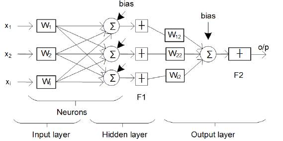
The structure of the neural network used is as follows
Input: X = X1, X2, X3... Xi.
Output: y = y1 y2, y3 …. Yn =o/p.
Weights of neurons: W= wi1, wi2, wi3...win.
The complete block diagram implemented for SAPF with ANN/PI controllers and adaptive HBCC with non-linear load is shown in Figure 5.
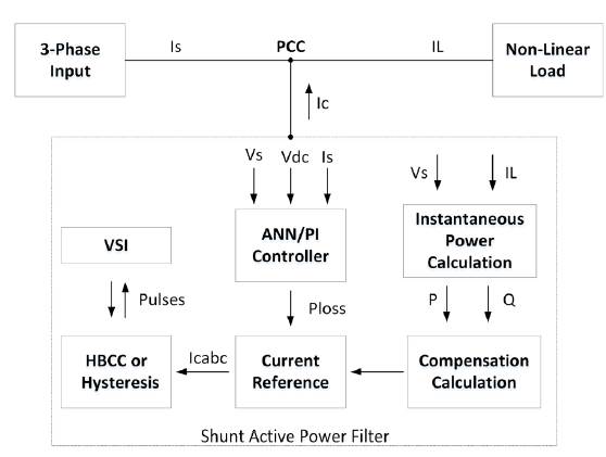
Conventional hysteresis and adaptive HBCC is used for gate signals. ANN and PI controllers are used to maintain the DC link voltage to constant value. The output of controllers and calculated instantaneous powers are then used in calculation of gate signals by using both the conventional hysteresis and adaptive HBCC.
Control structure of SAPF
The control scheme and structure of the SAPF used in the paper is shown in Figure 6. SAPF compensates the selective harmonic employing the Clark and inverse transformations defined earlier. The scheme is based on the cascade of two different independent controllers. DC-link voltage is employed with PI regulators and ANN to control Vdc to a fixed value. The output of PI controller is loss signal, where i(load,a) and i(load,b) are then used by the conventional hysteresis and adaptive HBCC for the calculation of the PWM signal and thus the generation of the sinusoidal waveform. The current controller consists of two PI regulators and an ANN used separately for reactive current compensation. The outer voltage control uses PI controller to compare the actual DC voltage with the reference signal and generate the output signal (ia) that is fed to the inner current control. PWM generates the gating signal (g1) used to produce the waveform of equal and opposite amplitude thus cancel the harmful harmonics from the system. Current control strategy is used in the reference generation frame.
Simulation results
The power system model considered for this work is shown in Figure 7. A diode bridge supplying a resistive load acts as a non-linear load. The most common examples are the power supplies for computers and mobile phones. Simulations and results were carried out in Matlab with neural network toolbox and Simpower Simulink platform. The results obtained from the proposed techniques are compared and in accordance with IEEE 519 standard limits. Simulations are run for a total time of 0,2s.
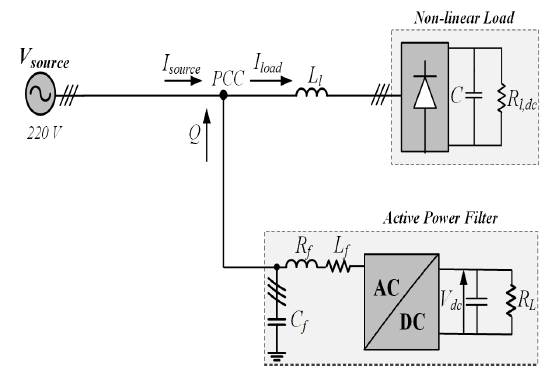
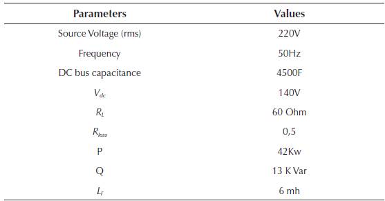
Table 1 presents the various parameters of the simulation model. Simulations are run for four different combinations, i.e. PI controller with conventional hysteresis controller; ANN with conventional hysteresis controller; PI controller with adaptive HBCC; and ANN controller with adaptive HBCC. The four combinations are defined in the following subsections.
A. PI Controller with Conventional Hysteresis Controller
First, simulations are performed without any compensation technique. At time t=0s, the load is connected to the network. Figure 8 shows the source current without load as well as its pure sinusoidal, load current and the distorted source current with nonlinear load. Figure 9 shows that THD without the use of compensation technique is 28,38%.
Source: Authors
Figure 8 (a) Source current. (b) Non-linear load current. (c) Distorted source current.
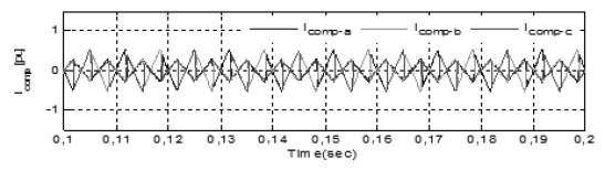
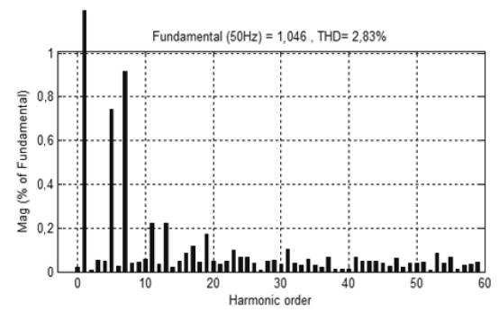
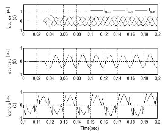
Then, simulations are performed with the combination of the PI controller and conventional hysteresis controller. Figure 10 shows the source current after compensation, DC-link, and the active and reactive component of load current with compensation technique. At time t=0s, load is connected to the network, where the SAPF is connected at time t=0,03s. Figure 10(a) shows that the source current has abridged to the minimum value and became sinusoidal at t=0,03s, because APF recompenses reactive power and harmonics of non-linear load. DC controller provides a very stiff control and voltage remains stationary to a definite value, as shown in Figure 10(b). The compensation current provided by the SAPF is shown in Figure 11. With this combination, THD is reduced to 2,83%, as presented in FFT Analysis in Figure 12.
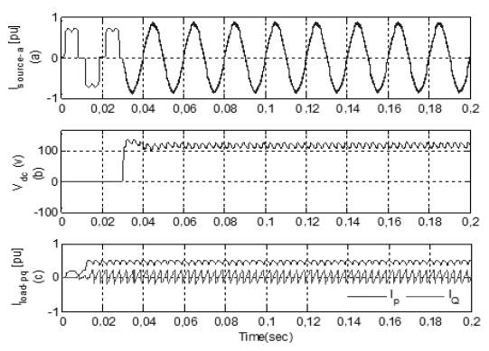
Source: Authors
Figure 10 (a) Source current. (b) DC-Link. (c) Active and Reactive of non-linear load.
B. ANN and Conventional Hysteresis Controller
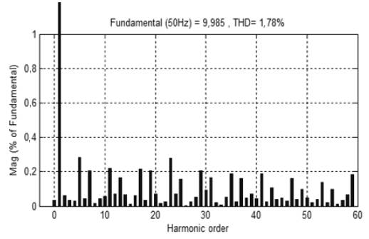
In the second case, simulations are performed with the combination of ANN and conventional hysteresis controller. Figure 13(a) shows the simulation results obtained with this combination. At time t=0,03s, SAPF is connected to the network and source current becomes sinusoidal because APF precisely injects the current to compensate the harmonics, as shown in Figure 13(b). THD of source current is reduced to 1,78% and is presented in Figure 14.
C. PI with Adaptive HBCC
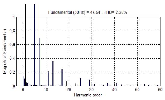
In the third case, simulations are performed with the combination of PI controller and adaptive HBCC. At time t=0,03s, the source draws a sinusoidal current, which indicates that the reactive component in the system becomes very low, as shown in Figure 15(b). THD in the source current is reduced from 28,38% to 2,28%, as depicted in Figure 16, which is in accordance with the acceptable range of IEEE 519 standards. However, in this case, THD is relatively high compared to the previous combination, mentioned in the earlier sections.
D. ANN with Adaptive HBCC
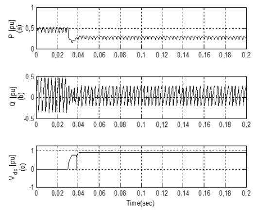
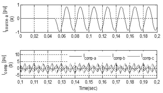
In the last case, simulations are performed with ANN and adaptive HBCC. ANN provides a very fast estimation of the reference current and is also used for DC-link, voltage regulation and current error adjustment. Active and Reactive waveform of the attached non-linear load is shown in Figure 17(a) and Figure 17(b), respectively. In Figure 18(b), FFT Analysis shows the compensation current injected in the system to mitigate the harmonics. FFT Analysis in Figure 19 shows that the THD in source current with this combination is reduced from 28,38% to 0,48%.
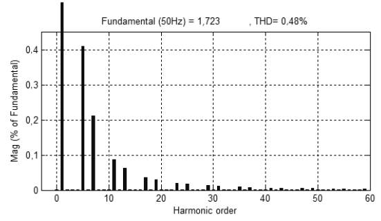
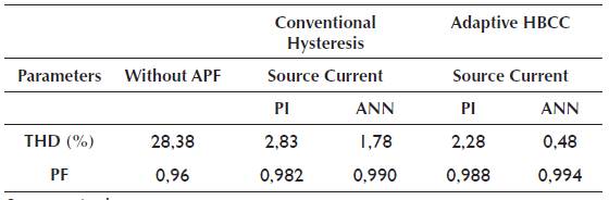
A comparison of simulation results is presented in Table 2. The best compensation is obtained by the combination of ANN with adaptive HBCC, which makes the source current almost perfectly sinusoidal with THD of 0,48% and power factor of 0,994, as shown below.
Conclusion
In this paper, SAPF control structure is modified using various controllers and with the combination of PI, ANN and hysteresis controllers. Reference signals are extracted using the IRP p-q approach. All the mentioned combinations of the controllers result in the reduction of THD down to acceptable standards. Simulation results, however, show that the combination of ANN and adaptive HBCC provides excellent compensation and is close to the perfect harmonic compensation. THD is reduced to a very low value, meaning the complete elimination of reactive power and harmonics drawn by the non-linear load.


