


 English (pdf)
 Article in xml format
 Article references
 Send this article by e-mail
 Cited by SciELO
  Cited by Google
  Similars in
SciELO
Similars in
SciELO  Similars in Google
 Permalink
Introduction
Bones are natural composite living tissues supporting the softer parts of the human body (Maharaja et al., 2013). They are approximately 60 % inorganic on a weight basis, 30 % organic, and 10 % water (Keaveny, Morgan and Yeh, 2004). Femur bone is the longest, strongest and heaviest bone in the human body with a length that is almost 26 % of the person height and a mass of about 0,455 kg (Popa, Gherghina, Tudor and Tarnita, 2006; Mughal, Khawaja and Moatamedi, 2015). The durability of biomaterials for prosthesis and orthopedic implants are of critical importance, mainly fabricated by using various alloys and metals to achieve the sufficient strength covered by the polymers biomaterials (Dhanopia and Bhargava, 2016).
Today the titanium, stainless steel, cobalt, chrome and zirconium are the most used biomaterials because of a favorable combination of corrosion resistance, mechanical properties and cost effectiveness (Shireesha, Ramana and Rao, 2013; Das and Sarangi, 2014). For artificial femur materials, different ceramic materials like alumina (Al2O3), hydroxyapatite, zirconia (ZrO2), Ti6Al4V and Al2O3/Al FGM are widely researched for implant applications due to their good biocompatibility (Ahmed, Rahman and Adhikary, 2013; Reddy et al., 2016).
Different synthetic hybrid biocompatible polymer-based matrices materials like polyethylene (PE), polyether ether ketone (PEEK), hydroxyapatite (HA), and poly methyl methacrylate (PMMA) are being used for bone scaffolds for potential load-bearing bone replacement and other biomaterial applications due to their durability, low cost, less weight, simple manufacturing, high strength and corrosion resistance. These biocomposites have also the advantages of high strength to weight-ratio, besides high specific modulus and superior fracture toughness (Bernhardt, Lode, Peters and Gelinsky, 2011; Lee et al., 2012; Mohammed et al., 2013; Nautiyal, Nain and Kumar, 2014).
The polyether ether ketone (PEEK) thermoplastic is an organic colorless thermoplastic polymer with its own high mechanical, thermal properties and chemical stability. The high biocompatibility of titanium dioxide (TiO2) has a wide range of applications, for orthopedic biomaterials. The bioinert ceramic aluminum oxide (Al2O3) is a chemical compound of aluminum and oxygen with high abrasion resistance and high hardness. It is commonly called alumina. Due to its high melting point, Al2O3 is a refractory material that naturally appears in a crystalline polymorphic phase a-Al2O3.
Long bones have different mechanical properties in the transverse and longitudinal directions, while loaded along different directions (Toth-Tascau, Rusu and Toader, 2010). The mechanical properties and structure understanding of natural bone is vital for developing new biomaterial bone implants. The mean fluctuating loads on the hip joint in general are expected to increase the body weight three to five times during jogging and jumping, depending on the human activities such as running, standing, sitting, staircase climbing, etc. (Mohammed et al., 2013).
Bone remodeling is a complex process that involves interactions between mechanical, biochemical, and mechanic-biological parameters to explain the relationship between mechanical forces and bone structure (Bougherara, Klika, Marsik, Marik and Yahia, 2010; Yousif and Aziz, 2012). Different efforts were made to analyze the stresses experienced by the human femur and CAD models were developed (Mughal et al., 2015). The 3D models of human femur were constructed by reverse engineering method and using finite element model under single, expanded loads (Zakiuddin, Khan, Roshni and Hinge, 2016).
During normal activities, the femur bone is subjected to tensile, compressive, and shear stresses. Shear stress magnitudes are relatively small, but can become significant in long bones subjected to torsion. Bone will fail along the weakest plane and this fracture plane coincides with maximum tensile stresses (Turner, Wang and Burr, 2001). The literature show that there is still a lack of predictive models despite the progress in bone remodeling and simulation using the finite element (FE) method (Hambli, 2014). The use of specific finite element models in orthopedic biomechanics still represents a challenge in the prediction of fracture risk and stress-state induced in bones under various loading conditions (Schileo, Taddei, Malandrino, Cristofolini, and Vicecont, 2007).
A limited number of researchers have worked on 3D modeling of the femur bone. In biomechanics, specific problems of the FEM are still difficult to model (Yousif and Aziz, 2012; Nautiyal et al., 2014). Research done by Nautiyal et al. (2014) has explored the replacement of defective bone for a perfect design and comfort of the patient including rotation, i.e. ease for changing direction, and weight for maximizing comfort, balance and speed (Nautiyal et al., 2014).
In the present work, the remarkable and promising properties of Titanium dioxide (TiO2) and Alumina (Al2O3) nano-ceramic particles were added for reinforcement of polyetheretherketone (PEEK) matrices to fabricate four types of hybrid bio-composites by using the powder metallurgy process. An attempt has been made to develop and study the effect of adding these nano-ceramic particles on the mechanical properties and inflammation behavior using animal model for the fabricated bio-composites systems. The aim of this study was to improve the biomechanical properties of these fabricated biomaterials to meet the wide demands for orthopedic application, particularly in bone and hip joint replacement.
The objectives of this study also included finding the best bio-material fatigue life and stress factor of safety to withstand the daily human normal walking, running and jumping activities loads. A three-dimensional femur bone geometry was initiated by using SOLIDWORKS 17.0 and it was modeled and analyzed by using finite element ANSYS 15.0 software programs. The response surface methodology (RSM) technique and the Design Expert software program were used to improve and verify the results of biomechanical properties of the fabricated biocomposites.
Experimental Procedure
Numerical analyses of biomaterial hard tissue are closely related to the selection of biomechanical properties and of biomaterials and implants (Sherekar and Pawar, 2013). In this study, four biocomposite materials were fabricated using a polymeric matrix of PEEK powder with an average particle size of 10 μm and a density of 1,3 g/cm3. The first material used was TiO2 ceramic filler of 99,9 % purity, average particle size of 40 nm and particle density equal to 4,23 g/cm3. The second material used was Al2O3 ceramic powder of 10 nm average particle size and a density of (3,890 g/cm2). The powders were mixed by using the micro powder ball mill mixing and grinding machine type YLK, rotated at 180 RPM for 12 h. Then, they were hot pressed at 180,190, and 200 °C and using a compounding pressure of 30, 60, and 90 MPa, respectively.
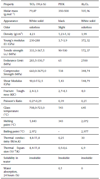
The four mixed biocomposites were prepared for implants with different compositions with composites of 10 vol. % of TiO2 and 90% PEEK, 20 vol.% of TO and 80% PEEK, 10 vol.% of TiO2 with 5 vol.% of Al2O3 and 85 % PEEK, and 20 vol. % TiO2 with 5 vol. % of Al2O3 and 75 % PEEK. The mechanical and physical properties of the PEEK, TiO2 and Al2O3 are presented in Table 1.
Table 1 Mechanical and physical properties of the PEEK, TiO2 and Al2O3
Source: Authors from Burgal, Peeva, Marchetti and Livingston (2015)
Then, the prepared biocomposites were compacted by using the hot-pressing powder metallurgical technique with an applied compression pressure of 50MPa under sintering temperatures of 370, 380, 390, and 400 °C. The fabrication process parameters with the experimentally obtained mechanical properties of the fabricated biocomposites and natural bones properties are given in Table 2.
Table 2 Mechanical properties obtained for the fabricated biocomposites and natural bones properties
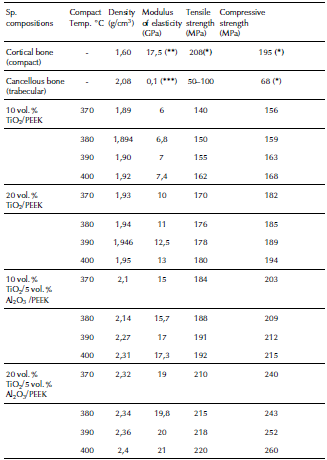
((*) MIT, 2006); ((**) Carter, Caler, Spencler and Frankel, 2017); ((***) Ibrahim, Daud, Zain, Izzawati and Bajuri, 2017)
Source: Authors
For examining the implant biological reactivity of the highest mechanical properties of the fabricated biocomposite, i.e. 20 vol.% of TiO2 with 5 vol.% of Al2O3 and 75% of PEEK, in vivo tests were implemented with cylindrical shapes in four breed rabbits to study the implants inflammation behavior. X-Ray radiographical examinations were implemented in all animals after 2, 4, 6 and 8 weeks, using Shimadzu digital x-ray machine grid type 2016/CRX10.
Modeling and Analyzing of Femur bone
The longest bone in human body is the femur, which is subjected to maximum deformation and compressive stresses. Finding these deformation and stress concentrations zones is very important in the femur bone implant (Amalraju and Dawood, 2012). The biomechanical behavior research on the femur bone is a hard task, since it is a live part in constant change and very complicated in terms of material properties, geometry, porosity and density. Finite element analysis (FEA) is the most reliable method among all of them (Taheri et al., 2012; Mohd Sheikh, Ganorkar and Dehankar, 2016). By using finite element analysis with different simulations, the weak points of the femur can be known, thus helping in the design and biomaterial selection (Zhang, Wang, Yu and Zheng, 2017).
In this work, the geometry of the human femur bone was implemented using the 3D Solidworks 17.0 software. The modeling dimensions of the bone were taken from a plastic copy of the adult bone. The modeling and analysis of human bone were done by using Ansys Workbench 15.7. The present bone model of the long femur was assumed to be homogeneous and isotropic. The suggested model for the real human bone was represented by two sections. The epiphysis part is made of spongy cancellous (trabecular) bone covered by a thin layer of compact trabecular bone. The bone model is also considered with two sections: the upper (epiphysis) edge part includes the head, neck and trochanters and the lower (diaphysis) edge is defined as the condyles (Dash, Kishor and Panda, 2013).
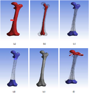
For modeling the natural femur bone composite, the process for creating the outer cortical bone part and the inner trabecular-bone part of the femur was done after importing the 3D model by creating a new part and using the freeze commands in ANSYS workbench. Then, the femur bone will appear as a complete femur bone (one piece) as shown in Figures 1a and b. The 3D finite element analysis (FEA) model of the femur bone was discretized by using a fine size volumetric meshing. To avoid unrealistic stress concentration points a mesh refinement was performed in the desired segments of the bone with higher gradients. The aim was to magnify the accuracy and ensure the quality of results, as shown in Figure 1c for modeling the natural femur bone composite and 1d and 1e for modeling the fabricated femur biocomposite bone. The number of created nodes is 39 957 and 19 480 elements.
Source: Authors
Figure 1 Modeling of femur bone: (a) natural outer part as cortical bone part; (b) natural inner part as trabecular bone; (c) mesh refinement of the natural bone; (d) mesh refinement of the fabricated biocomposite bones; (e) the resulted mesh refinement of the bones; (f) mesh refinement of the fabricated biocomposite bones.
In the present study, the stress analysis called multiphysics static structural analysis is used to determine the dynamic response of loads on the head of the femur during the hardest activity of the gait cycle (Qasim et al., 2016). The bone was analyzed for stresses/forces during running and jumping activities. The femur bone was considered as an inflexible and solid condition. The resulting loads at the hip joint contact for these complicated activities are applied on the femoral head contact area and the other end lower part surface of the bone, i.e. the lateral condyle installed by a fixed support (free clamped for all degrees of freedom).
At walking activities with a speed of more than 5 km/h and during running and jumping activities, a longitudinal compressive load was simulated for an average adult male patient. Weight of 750 N was applied on the femoral head eccentrically and concentrically at the extremes with a maximum inclined angle of knee joint considered as a couple torque force (moment) of 10 N.mm applied normal to the long edge of the implant (Toth-Tascau et al., 2010; Ahmed et al., 2013). The applied loads components in -x, -y and -z directions are the human weight * cos 30° * tan 30°, weight * cos 30° * sin 30° and weight * cos 30° * cos 30°, respectively. The applied moment components were calculated in the same manner and directions using a moment value of 10 N.mm. The boundary conditions of the modeled femur bone are shown in Figure 1f.
Results and Discussion
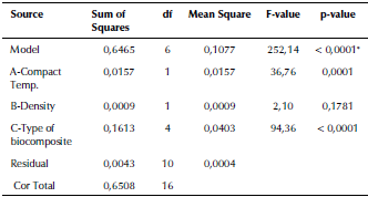
The main contribution of this study is to create a simulation model that can demonstrate the highest stresses, strains distribution and fatigue failure of the natural femur bone and for the fabricated nano-composites for bones replacements. The performance of the mechanical properties in the modeling results for the natural femur bone and all the fabricated biocomposites are given in Table 3.
Table 3 Results of the performance of mechanical properties for the natural femur bone and the fabricated biocomposite materials
Source: Authors
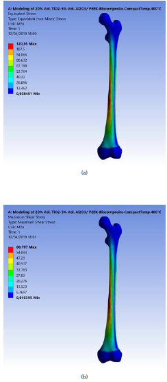
The resulting maximum equivalent (von-Mises) and shear stresses for the applied force and moment on the modeled femur bone is 120,93 and 60,80 MPa, respectively, as shown in Figures 2a and b. These stresses increased in the middle uniform part of the bone, where fractures are expected, as confirmed by most cases of injury and fractures in various accidents. Senthil Maharaj, Maheswaran and Vasanthanathan reported that the maximum equivalent stress is generated at the middle section of the femur. It reached 65,35 MPa in the study of Maharaja et al. (2013), while Ahmed et al. (2013) concluded that the von-Mises stress distributions on the surface of the implanted femur are 128,05 MPa in stance and 1 127,8 MPa in fall.
Source: Authors
Figure 2 (a) Maximum equivalent (von-Misses) stress on the modeled femur bone; (b) Maximum shear stress.
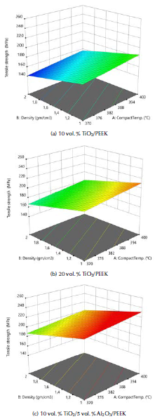
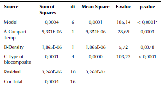
In the present work, the experiments were designed using the response surface methodology (RSM) and the full factorial method (FFM). The results were analyzed using an analysis of variance (ANOVA) technique. Table 4 presents the ANOVA analysis of the tensile strength resulting from changing the compact temperature and the density of the fabricated biocomposite materials. The F-value of 258,81 implies that the model is significant. The 3D graphs for the tensile strength of the fabricated biocomposite materials are shown in Figure 3. These graphs show that the maximum tensile strength reached 220 MPa when modelling the fabricated 20 vol. % TiO2/5 vol. % Al2O3/PEEK biocomposite material.
Table 4 ANOVA analysis of the tensile strength for the fabricated biocomposite materials
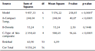
* significant
Source: Authors
Source: Authors
Figure 3 3D graphs for the tensile strength of the fabricated biocomposite materials.
This value is higher than for natural femur bone by 10%. The tensile strength value increased with the compact temperature during the powder metallurgical process. The increase in the density also helped to obtain higher tensile strength values because it means an increase in the molecular bouncing of the crystal structure. Increasing the proportion of titanium dioxide nano-ceramic material to the base PEEK material also increased the durability, as these materials possess high mechanical properties such as the tensile strength, endurance limit and compressive strength. This strength increased considerably by increasing the alumina particle ratios because its endurance limit and fracture toughness improved significantly. This conclusion agrees with Mohammed et al. (2013), whose study showed that the tensile strength of biocomposite materials increase with higher filler contents percentage of Al2O3 and of TiO2.
The external mechanical work causes the elastic deformation of the femur bone structure in daily human activities, as movement is transformed into internal strain energy. The bone failure occurs when the maximum shear strain energy component is equal to the corresponding value at the yield point in the tensile test. The ANOVA analysis of the internal strain energy of the fabricated biocomposite materials are given in Table 5. The F-value of 195,28 implies that the model is significant. The 3D graphs show that the strain energy values increased with the biomaterial density and vice versa, with the tensile strength, the elastic strain and compact temperature, as shown in Figure 4.
Table 5 ANOVA analysis of the internal strain energy of the fabricated biocomposite materials
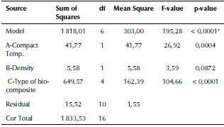
Source Authors
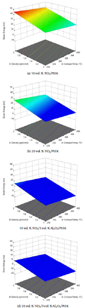
Source: Authors
Figure 4 3D graphs for the internal strain energy of the fabricated biocomposites materials.
These graphs show that the lower maximum strain energy values are due to external loadings for these complex states of stress systems. This was obtained with the model of the natural femur bone and the best fabricated biocomposite material (20% vol. TiO2/5% vol. Al2O3/PEEK) at the highest compact temperature of 400 °C. Strain energy values were equal to 15,61 and 13,01 m.J., as shown in Figures 5a and b. The strain energy was reduced by 20 %, when compared with the natural femur bone material. This means that for this type of fabricated biocomposite material, the required value of the strain energy conversion into mechanical kinetic energy and the rising in the temperature generated is the lowest. This is in favor of patients who are fractured and injured and undergo partial repair or replacement of femur bone. For the same human weight, the maximum displacement that Amalraju et al. (2012) found was 0,0012 mm, and values of 0,0012 for Ti6Al4V and 0,0036 for Al2O3/Al FGM were reported by Ahmed et al. (2013).
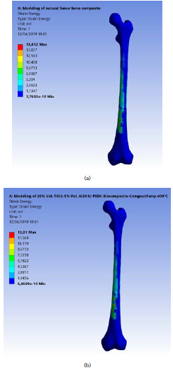
Source: Authors
Figure 5 (a) Maximum strain energy of the natural modeled femur bone; (b) for the fabricated (20% vol. TiO2/5 % vol. Al2O3/PEEK) biocomposite at compact temperature of 400 °C.
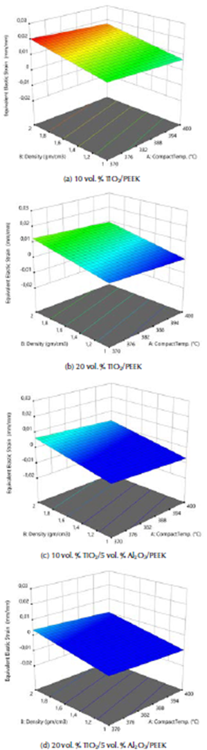
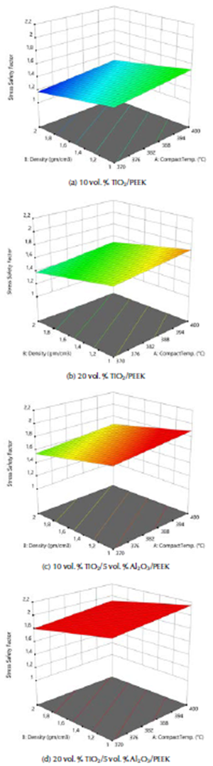
ANOVA analysis of the equivalent elastic strain and the stress safety factor values for all the examined biomaterials are listed in Tables 6 and 7. The F-values of 185,14 and 252,14 imply that the models are significant. The 3D graphs show that the equivalent elastic values increased with the decrease in the biomaterial density and in compact temperature, as shown in Figure 6. Figure 7 shows the 3D graphs of the stress safety factor values, which decreased with the increase in the biomaterial density and in compact temperature.
Table 6 ANOVA analysis of the equivalent elastic strain of the fabricated biocomposite materials
Source: Authors
Table 7 ANOVA analysis of the stress safety factor of the fabricated biocomposite materials
Source: Authors
Source: Authors
Figure 6 3D graphs for the equivalent elastic strain of the fabricated biocomposite materials.
Source: Authors
Figure 7 3D graphs for stress safety factor of the fabricated biocomposite materials.
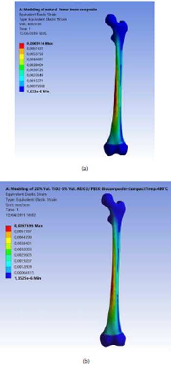
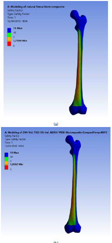
The maximum equivalent elastic strain and the stress safety factor values for the best fabricated (20 % vol. TiO2/5 % vol. Al2O3/PEEK) biocomposite material were obtained at compact temperature of 400 °C in the simulation model, resulting from the external loads applied on the femur. These values are the lowest of all types of the fabricated biocomposite materials and for all the compact temperatures used, reaching 0,0051 mm/mm and 1,82. These equivalent elastic strain and stress safety factor values are better than the values obtained for the modeled natural composite femur bone, which reached 0,0069 mm/mm and 1,72, by 26,09% and 5,81 %, as shown in Figures 8a and b and 9a and b, respectively. These values are highly important for helping the patient's replaced femur bone to carry higher external loads and weights and withstand any sudden dynamic movement events, which are expected to occur within the daily activities of life.
Source: Authors
Figure 8 (a) Maximum equivalent elastic strain of the modeled natural femur bone; (b) for the fabricated biocomposite (20% vol. TiO2/5% vol. Al2O3/PEEK) at compact temperature of 400 °C.
Source: Authors
Figure 9 (a) Maximum stress safety factor of the modeled natural femur bone; (b) for the fabricated biocomposite (20% vol. TiO2/5% vol. Al2O3/PEEK) at compact temperature of 400 °C.
To calculate the fatigue lives in cycles for the natural femur bone, all the four fabricated biocomposites at all compact temperatures are used. Firstly, endurance (S’e) should be calculated from the ultimate tensile stress (Sut) values limit by using the following equation (Shigley and Mischke, 2006):
 The modified endurance limit (S) can be found as:

where the Surface Condition Factor (ka) for grinding surface is equal to:

The size Factor (kb) for bending and torsion (assuming that the mean diameter of the femur bone is equal to 25 mm) is:

The loading factor (k c ) for bending and torsion is:

The temperature factor for human life (k d ) = 1. For 99 % reliability, the reliability factor corresponds to 8 % standard deviation of the endurance limit (k e ) = 0, 82. The miscellaneous-effects factor (k f ) = 1. Then, the modified endurance limit (S e ) can be obtained by using equation (2). The fatigue life, i.e. the number of cycles to the failure (N) at a given fatigue stress (σ), is found as:

where:
The fatigue lives (σ) and the results of all the fabricated biocomposite materials were calculated for all fatigue stresses, as well as for the natural femur bone for all the stress rates, starting from the tensile strength to the endurance limit stress values with a difference of 5 MPa.
These results with the mechanical properties obtained from the experimental tests, presented in Table 2, have been introduced in the engineering date of the ANSYS 15,7 software program.
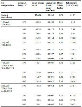
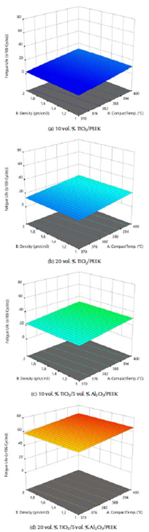
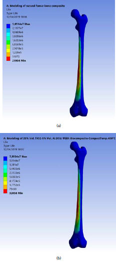
The ANOVA analyses of the values of fatigue life for the fabricated biomaterials are listed in Table 8. The model F-value of 227,69 implies that the model is significant. The 3D graphs show that the fatigue life values increased with the biomaterial density and compact temperature, as shown in Figure 10. Figure 11 shows the maximum values of fatigue lives of the modeled natural femur bone and for the best result of the fabricated biocomposite (20% vol. TiO2/5% vol. Al2O3/PEEK) at compact temperature of400 °C, reaching 50,51 and 70,93 x 10⁶ cycles, respectively.
Table 8 ANOVA analysis of the stress safety factor of the fabricated biocomposite materials
*significant
Source: Authors
Source: Authors
Figure 10 3D graphs for stress safety factor of the fabricated biocomposite materials.
Source: Authors
Figure 11 (a) Maximum fatigue life of the modeled natural femur bone; (b) for the fabricated biocomposite (20% vol. TiO2/5 % vol. Al2O3/PEEK) at compact temperature of 400 °C.
These results show that the fatigue life for the fabricated biocomposite is 40,43 % more than that of the natural femur bone life. These results give hope to bone fractures and osteoporosis patients to use successful biocomposite substances in the in vitro and in vivo tests with good durability, flexibility and a better life performance.
Conclusions
The maximum equivalent (von-Misses) and shear stresses on the modeled femur bone are 120,93 and 60,80 MPa.
The tensile strength increased with the compact temperature and the density. The maximum tensile strength reached 220 MPa when modeling the fabricated biocomposite of 20 vol. % TiO2/5 vol. % Al2O3/PEEK material. This value is higher than that for natural femur bone by 10%.
The lower maximum strain energy values obtained with the modeled the natural femur bone and the best fabricated biocomposite (20% vol. TiO2/5 % vol. Al2O3/PEEK) at the highest compact temperature of 400 °C are equal to 15,61 and 13,01 m.J., respectively. The strain energy was reduced in 20%, when compared with natural femur bone material.
The maximum equivalent elastic strain and the stress safety factor values for the best fabricated biocomposite (20 % vol. TiO2/5% vol. Al2O3/PEEK) at compact temperature of 400 ° C reached 0,0051 mm/mm and 1,82, respectively. These equivalent elastic strains and these values are better than those obtained for the modeled natural femur bone composite by 26,09% and 5,81 %, respectively.
The maximum values of fatigue lives for the modeled natural femur bone and for the best fatigue life result of the fabricated biocomposite (20% vol. TiO2/5% vol. Al2O3/PEEK) at compact temperature of 400 °C reached 50,51 and 70,93 x 10⁶ cycles, respectively. These results show that the fatigue life for the fabricated biocomposite is 40,43 % more than that of the natural femur bone life.


