


 Inglês (pdf)
 Artigo em XML
 Referências do artigo
 Enviar este artigo por email
 Citado por SciELO
  Citado por Google
  Similares em
SciELO
Similares em
SciELO  Similares em Google
 Permalink
Introduction
The hand is one part of the human body that has a significant role in carrying out daily activities. People with hand disabilities require a wearable robot that can help them perform as they did before. Two types of wearable robots are widely used for people with hand disabilities: prostheses and exoskeletons. Prosthetic hands, especially myoelectric hands, are an option for people who have lost a hand. There are many commercially available devices of this kind in the market today, but their price is not low enough (Ku, Lee, Park, Lee, and Jeong, 2019). Marks and Michael (2001) even stated that the cost have quadrupled as microprocessor control has steadily increased. Birnbaum (2016) stated in his report that these devices are a luxury rather than a necessity. The World Health Organization (Hill and Krug, 2017) underlined that, without access to prostheses or orthoses, people who need them are often excluded, isolated and condemned to poverty. Based on this, many researchers have been developing 3D-printed myoelectric hands intended as low-end products (Sreenivasan et al., 2018; Yoshikawa, Sato, Higashihara, Ogasawara, and Kawashima, 2015; Slade, Akhtar, Nguyen, and Bretl, 2015; Kamikawa and Maeno, 2008). A myoelectric hand can be operated by the wearer through an electromyography sensor that is placed on the remainder of the human limb. This sensor can read EMG signals from residual nerves through muscle contractions, but there are still manyflaws (Balciunas, Murphy, and Zdonbinski, 2019; Geethanjali, 2016). Most devices still use hard robot technology and are limited to EMG signal acquisition (Ribeiro et al., 2019).
Researchers from around the world have developed exoskeleton hands by using hard materials or hard robot technology. People with impaired hands such as stroke hand issues or brachial plexus injuries need an exoskeleton hand to assist their motion. The exoskeleton is aimed to assist and provide mechanical support for the human joints in the hands, fingers, elbows, etc. A hard exoskeleton hand is rigid and easier to control than its soft variant. However, it is limited in the sense that it is hard to align with a human hand, not comfortable, and still heavy (Ho et al., 2011; Pu, Chang, Pei, Kuo, and Wang, 2016; Gearhart, Varone, Stella, and BuSha, 2016; Ismail, Ariyanto, Pambudi, Syafei, and Ananto, 2017).
Recently, many researchers have developed soft exoskeleton hands to overcome these limitations, even though they are more difficult to control. Three types of commonly used actuation systems in soft exoskeleton are pneumatic network (Polygerinos et al., 2013; Yun, Kang, and Cho, 2017; Yap et al., 2015, 2016), shape memory alloy (SMA) (Villoslada, Flores, Copaci, Blanco, and Moreno, 2015; Hadi, Alipour, Kazeminasab, and Elahinia, 2018), and motor-tendon actuation (Randazzo, Iturrate, Perdikis, and Millán, 2018; Kim, In, Lee, and Cho, 2017; In, Kang, Sin, and Cho, 2015). The control design and actuation system for these hands have become one of the most challenging issues in developing soft exoskeleton robots. Soft exoskeleton hands have are now a potential wearable robot and an assistive device for people with impaired hands. They also can be used for hand rehabilitation purposes.
According to the above, this study develops a wearable soft exoskeleton glove that will be used as an assistive device for people with impaired hands. A soft glove is generated by using RTV (room-temperature vulcanizing) silicone rubber material, while the actuator system is a motor-tendon actuator incorporating fuzzy logic control. Two Bowden cables are used as power transmitters from the motor-tendon actuator to the soft glove to perform flexion and extension movements as mechanical support. After the soft exoskeleton glove prototype is developed, a test on a healthy human hand is conducted to determine the performance of the robot. Aditionally, the grasping test is performed using various objects with different shapes, sizes, and masses.
Methodology
A soft exoskeleton glove
This study begins to model the soft exoskeleton glove by determining the average dimensions of the fingers and hands for brachialis plexus injury patients, in order to get the best glove size configuration. Modeling is carried out by developing a 3D design using CAD software (SolidWork®). The 3D soft glove design is shown in Figure 1, and the next step is to design a mold design based on it.
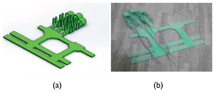
Synthetic rubber is used as a soft glove material. According to its manufacturing temperatures, there are two types: those that require heating and those that do not, which are called RTV (room-temperature vulcanization) silicone. RTV silicone has many types based on the type of mixture, stiffness, and heat resistance. In this study, RTV silicone rubber was chosen as the material for the soft glove because it makes the manufacturing process easier. This process does not require heating, and this study worked at low temperatures. Several types of materials such as RTV 48, RTV 52, and RTV Platinum were used, out of which the latter was chosen since it has the highest stiffness. During the casting process, RTV Platinum can enter and fill the narrow gaps in the soft glove mold to yield better results. Soft exoskeleton glove manufacturing results are shown in Figure 1.
Motor-tendon actuator
This section discusses the kinematic modeling of the motor-tendon actuator based on the rotation pattern of the servo motor, which is used as the main driver to pull the sheath tendon. The modeling discusses the kinematic model of x displacement for the motor-tendon actuator to model linear displacement into potentiometer sensor rotation (position control).
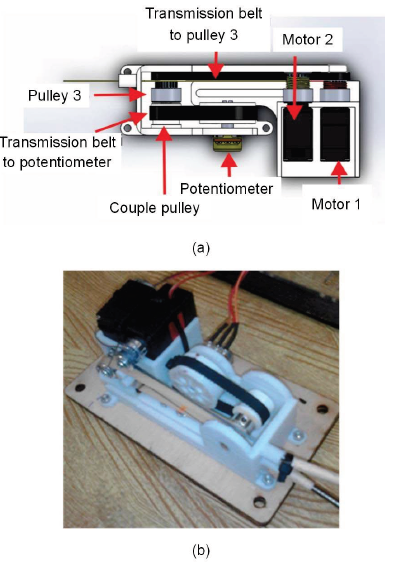
Figure 2 shows the design configuration of the motor-tendon actuator. It is worth noting that the purpose of kinematic modeling is to provide feedback control to the used actuator - in this case, a DC motor. Feedback is a signal from the potentiometer sensor in the actuator system. The potentiometer used in this study has a range of motion of 270°, while the DC motor rotation pulls the tendon-sheath from the normal position to the full grip position that requires more than one rotation. Therefore, a rotary reduction between the potentiometer and the DC motor is needed, so that the actuator rotation does not exceed the range of motion of the potentiometer. Figure 3 shows a reduction system using four pulleys.
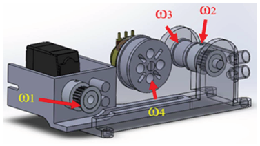
The DC motor pulley is represented by ω1 as the initial reference point of the round, which acts as an actuator, while the pulley on the coupled shaft is represented by ω2 and ω3. The potentiometer pulley is represented by ω4. The calculation of the reduction system has the purpose of determining how much reduction occurs in the motor-tendon actuator. This reduction pulley calculation starts from the pulley of a DC motor. Pulleys 1 and 2 are connected to the belt so that their linear velocity is the same. Thus, the equation can be written as follows:

where r 1 = r2, then ω1 = ω2.
Pulleys 2 and 3 are coupled using a shaft so that there is a relation between them. Pulleys 3 and 4 are connected by a belt so that the linear speed between the two pulleys is the same, and the equation can be written as follows:
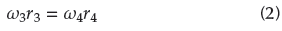
Based on calculations in Equations (1), (2), and (3), a range of motion can be found from the sheath tendon. The diameter of a DC motor pulley is 10 mm, the maximum analog to digital converter (ADC) value from the potentiometer in the motor-tendon actuator is 746, and the minimum ADC value is 97. The calculation of the range of motion from sheath tendon is stated in Equation (3), (4), and (5).
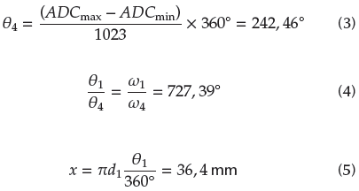
From the results of these Equations, the obtained length of the tendon pull is 36,4 mm.
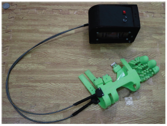
The development of the exoskeleton glove was conducted in our previous study (Setiawan, et al., 2020). Some of the soft exoskeleton glove and motor-tendon actuator manufacturing processes have been described in the research. After the manufacturing processes, the assembly process of all components, including the soft glove, the motor-tendon actuator, the motor-tendon actuator case, two Bowden cables, and electrical components were carried out. The wearable robot soft exoskeleton glove that has been completed through the assembly process is shown in Figure 4. The motor-tendon actuator can be worn on the waist of the user/wearer.
Control Mechanism
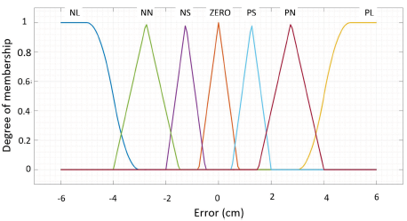
The selected method for controlling the employed DC motor is fuzzy logic control (FLC), whose implementation stages will be presented in this section. There are three main components in a FLC design: input, rule, and output. The output value used in the FLC is the pulse width modulation (PWM) value. The PWM value adjusts the movement of the motor clockwise or counterclockwise and increases or decreases the speed of the DC motor. The rule component is a fuzzy logic that is used for the produced output in accordance with the input. The three main components produce logic, which is then used for motor movement control in the actuator. The input used in fuzzy logic is an error value. Therefore, before designing the input part of the Fuzzy Logic Designer, it was necessary to determine the boundary of the error value that is used as the so-called the input membership function in this study. It is identified and summarized in Table 1.
Table 1 Membership function input command identification
| Error | Error Identification | Symbol |
|---|---|---|
| 6 cm - 4 cm | Positive Large | PL |
| 4 cm - 2 cm | Positive Normal | PN |
| 2 cm - 0 cm | Positive Small | PS |
| 0 | Zero | Zero |
| 0 cm - (-2 cm) | Negative Small | NS |
| (-2 cm) - (-4 cm) | Negative Normal | NN |
| (-4 cm) - (-6 cm) | Negative Large | NL |
Source: Authors
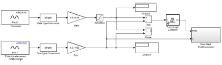
The rotational speed of the DC motor is controlled using PWM. When the value of PWM is positive, the motor pulls the tendon to move in flexion. However, while the value is negative, the motor stretches the tendon, or the soft glove position returns to its normal position. The output membership function response is identified in Table 2. After the membership functions of the input and the output are determined, the next step is to design a rule or logic. The employed logic is "if" and "then", which means that if the input X has been determined, then the output Y will be produced. The rule used in motor control in this study can be seen in Table 3. The embedded control block of the wearable soft robotic glove with FLC is shown in Figure 5. The FCL is developed with a Simulink block diagram, as shown in Figure 6. The reading of a potentiometer or electromyography (EMG) sensor is applied using analog input block with a sampling frequency of 50 Hz.
Table 2 Membership function output response identification
| PWM | PWM Identification | Symbol |
|---|---|---|
| 0 - 6 cm | Positive PWM | P_PWM |
| 0 cm | Zero | Zero_PWM |
| (6cm) - 0 cm | Negative PWM | N_PWM |
Source: Authors
Table 3 Fuzzy logic rule
| Logic | Error | Logic | PWM |
|---|---|---|---|
| PL | P_PWM | ||
| PN | P_PWM | ||
| PS | P_PWM | ||
| lf | Zero | Then | Zero_PWM |
| NS | N_PWM | ||
| NN | N_PWM | ||
| NL | N_PWM |
Source: Authors

Results and Discussion
In this section, the results of testing the soft exoskeleton glove control performance will be implemented on healthy human hands. Performance control testing is performed by comparing the results of the test, given the command and the resulting response. The control performance test is conducted by comparing the results between with and without load. The 'without load' category implies that the soft exoskeleton glove is not worn by a user, while a 'with load test' means that the soft exoskeleton glove is worn on a healthy human hand.
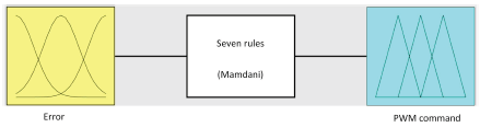
Fuzzy Inference System (FIS) is one of the algorithms used for decision making. In fuzzy logic designs, there are three main parts, namely input commands, rules, and commands or fuzzy logic, which are designed based on the input, and consequently respond as the produced output. The FIS for this study is shown in Figure 7.
Before the fuzzy logic performance test is carried out, it is necessary to fine-tune the membership input and output functions in the fuzzy logic designer to get a control response that matches the objectives. In this study, the tuning was performed six times to identify the best response from several conducted experiments. Table 4 shows the PWM value entered in the membership function.
Table 4 Value of membership function for PWM command
| No | Trial | Parameters | ||
|---|---|---|---|---|
| Negative PWM | Zero | Positive PWM | ||
| 1 | Tuning 1 | [-150 -60] | [-80 0 80] | [60 150] |
| 2 | Tuning 2 | [-130 -20] | [-70 0 70] | [20 130] |
| 3 | Tuning 3 | [-180 -20] | [-90 0 90] | [20 180] |
| 4 | Tuning 4 | [-220 -20] | [-120 0 120] | [20 220] |
| 5 | Tuning 5 | [-200 20] | [-110 0 110] | [20 200] |
| 6 | Tuning 6 | [-150 -20] | [-100 0 100] | [20 150] |
Source: Authors
From several experiments in tuning that input into the membership function plot, the best response was obtained in the third trial. The best plot obtained from the input membership function is shown in Figure 8.
Membership Function Output is the PWM limit value entered in the output dialog box. The values entered are for a negative PWM from -180 to -20, as well as a positive PWM from 20 to 180. For typical values, as well as those in the plot, which are depicted with zero-lines, the entered value is -90 to 90. The best plot obtained by the membership function output as a response representing the value of the PWM output is shown in Figure 9.
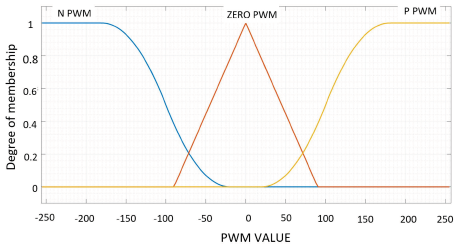
The output membership function that occurs in accordance with the PWM value is shown in Figure 9. If the PWM value is positive, the motor pulls the tendon, which is represented by the orange line (positive PWM). When the PWM motor is negative (negative PWM), the motor stretches the tendon, or the soft glove position returns to normal, which is represented by the blue line.
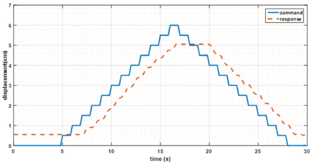
The Simulink block diagram is built and then embedded in the Arduino Mega 2560 microcontroller for data retrieval. The data is taken in the form of steps and a trajectory following input and output in terms of time. Tests are carried out with and without load so that the data is obtained, which is then carried out data plots. Figure 10 shows the step signal input and output plots with respect to time.
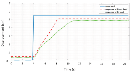
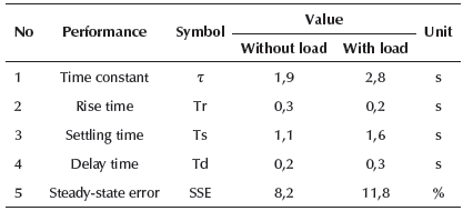
Figure 10 reveals the command signal represented by a blue line. The red-dashed lines represent the without-load response signal, while the green dot line represents the response signal with a load. The performance of the transient response system based on the test is shown in Table 5. "Without-load" means that the soft exoskeleton glove was unattached on the human hand, whereas "with a load" means that the soft glove was attached to the human hand.
The trajectory following command is used for the input and output signals to determine the suitability of the response to the given command. The results of the trajectory graph of the given signal command and the response ares shown in Figure 11. Based on these results, there is a delay of about 1 second.
Object Grasping Test
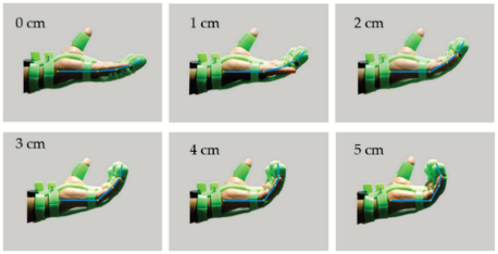
In this section, the results of the test with and without load will be discussed. The no-load test was carried out by pulling the sheath tendon every 1 cm to observe the curvature that was formed in the soft exoskeleton glove. Figure 12 shows the test results of the movement by pulling the sheath tendon. Based on the test results, there is a change in the angle of 67° on the first segment of the finger by pulling the sheath tendon from 0 to 5 cm.
Source: Authors
Figure 12 The trajectory of the finger when the soft exoskeleton glove is worn by the user.
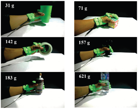
In the next test, the soft exoskeleton glove is used to assist and provide mechanical support to the user's hand. In this test, the glove is attached to healthy human hands. The test results are shown in Figure 13. Based on these results, the soft exoskeleton glove can assist and provide mechanical support in grasping six various objects of different sizes, shapes, and masses.
Based on the previous study using PI compensator for controlling the exoskeleton glove (Setiawan, et al., 2020), FLC has a better performance and faster response compared to PI compensators. The video performance of the developed soft exoskeleton glove for providing mechanical assistances worn by a user can be seen online at https://www.youtube.com/watch?-v=497cCqo5V5M&t=13s
Conclusions
In this study, a soft exoskeleton glove prototype with the motor-tendon actuator was successfully developed. It consists of three main components in the working system: soft glove, tendon sheath, and motor-tendon actuator. The fuzzy logic control design for controlling the motion of the soft exoskeleton glove has been successfully developed and implemented. The best-obtained values for negative PWM are from -180 to -20, and the positive PWM values range between 20 and 180. The soft exoskeleton glove was able to pull the first segment of fingers of the user up to 67° which produced the curvature that was necessary for grasping. The soft exoskeleton glove can assist the user in grasping various types of objects with variations in shape, size, and mass.

