


 English (pdf)
 Article in xml format
 Article references
 Send this article by e-mail
 Cited by SciELO
  Cited by Google
  Similars in
SciELO
Similars in
SciELO  Similars in Google
 Permalink
Introduction
Structural engineering always aims for the best way to represent a real structure in a mathematical model in order to obtain the best approach to the reality. Soil-structure interaction is one of many ways to get closer to the behavior of a real structure. There are many ways to represent this relationship: it could be static or dynamic, linear or non-linear, and the possible combinations among them (Zeevaert, 1980; Mejía-Bermejo, 2017; Hernández-Velasco, 2013; Galicia and León, 2007; Villareal, G. 2009). To represent soil and substructure displacements, it is necessary to calculate the foundation system, in order to substitute it with equivalent springs using the concepts of rotational and translational stiffness (Uribe-Escamilla, 2000; Weaver and Gere, 1990; López et al., 2019), which express that a structural element can be represented through its rotational and translational stiffness coefficients, as shown in Equations (1) and (2).

where F is the force applied on a structural element; K T is the element's translational stiffness constant; d is the displacement in the force's direction; M is the torsional or bending moment applied on the structural element; K R is the element's rotational stiffness constant; and θ is the rotation in the moment's direction. To make soil-structure interaction possible, it is necessary to obtain the values of F, d, M, and θ. Thus, the values of K T and K R , can be calculated for each direction, representing the equivalent spring constants for the foundation system, as shown in Figure 1. It is worth noting that that K T and F = K R remain linear, with a single value for each direction (Wu and Pantelides, 2019).

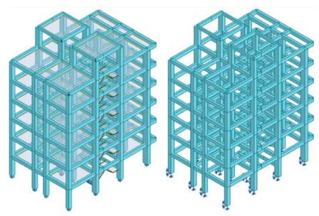
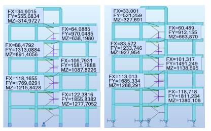
After calculating the equivalent springs, the initial structural model fixed at the base is submitted to a new structural analysis using springs (Figure 2), thus allowing changes in global stiffness and, hence, a variation in the results.
Methodology
This research was based on basic structural concepts for soil-structure interaction in linear range. The structure used for this research was residential and consisted of six levels, one elevator, one stair module, with 3 types of foundation soil and spectral parameters typical from Quito, Ecuador. The main objective of this research was to quantify the differences in seismic response and structural members design of the same regular reinforced concrete structure using soil-structure interaction in linear range. Basic structural dynamics applied to building analysis and design explains how to obtain the main structural criteria in order to accept or reject the structural member cross section, with the vibrational modes, periods, and drifts being the most important, including the force diagrams for structural member design. Based on the basic concepts of structural dynamics, the modal matrix and the structure's frequencies can be calculated from Equations (3), (4), and (5).
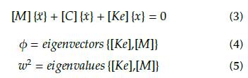
where [Ke] is the structure's equivalent stiffness matrix, which depends on the cross section, inertia, length, supports, and material of each structural member for 2D planar analysis; [M] is the mass matrix of the structure; [C] is the matrix of damping factor, which is considered to be constant in this research; X is the structure acceleration vector; X is the structure velocity vector; Ф is the structure displacement vector; p is the modal matrix; and w is the angular velocity for each vibrational mode.
In this research, three different inelastic spectra were considered, and the general solution was obtained by performing modal-spectral analysis, with modal truncation for three vibration modes per floor, and then obtaining the response of each degree of freedom (DOF) by applying Equations (6) and (7).

where ζ n is the damping value per mode; w n is the angular velocity per mode; D n is the modal displacement value per mode; ug is the spectral acceleration; i is the directional vector for the spectral acceleration (x, y, z); un is the displacement for each DOF and each vibrational mode; m is the modal mass; and n is the number of each vibrational mode. The total response is estimated through the CQC method. These calculations were made with Autodesk Robot Structural 2020, academic version (547L1, 900-95470127).
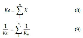
The [Ke] factor is the key for the structural changes in results using soil-structure interaction due to the change in stiffness in the first level, which directly affects global stiffness. If a structure is assumed to be fixed at the base or uses equivalent springs, stiffness changes according to the case. The fixed element has translational and rotational restrictions at the base, whereas the non-fixed element has no restrictions, thus allowing displacements and rotations at the base and increasing displacements. According to the literature (Falcon, 2008; Chopra, 1980); Reyes, 1998; Paz, 1992), stiffness decreases are in accordance with equivalent stiffness theory, which expresses an equivalence with the configuration through Equation (8), for springs in parallel arrangement, and Equation (9), for springs in continuous arrangement.
The stiffness modification at the base directly affects the [Ke] structure matrix, modifying the periods, frequency, modal response, and modal displacements. Some studies express that damping is another important factor (Lutes and Sarkani, 1995; Cruz, and Miranda, 2017). However, this value has remained constant, imposing a 5,00% damping value corresponding to structures provided with reinforced concrete.
Analysis and discussion
Inelastic design spectrum
This research was based on three typical soil types from the city of Quito, Ecuador, with an acceleration value on rock according to a seismic hazard of 0,40 g. The three soil types were A, C, and E, based on the scale from A to E, with A being the best soil type, with a shear wave velocity greater than 1500,00 m/s; C, an intermediate soil, with shear wave velocities between 360 m/s and 760 m/s; and E, the worst soil type, with a shear wave velocity of less than 180 m/s. The inelastic spectrum by soil type used for the analysis are shown in Figure 3, as a fraction of gravity according to the Ecuadorian building regulations for seismic hazard (NEC, 2014).
Fixed superstructure analysis and design
The first step in the analysis is the correct design of the structure, in accordance with the regulations (ACI, 2014 2019; NEC, 2015; ASCE/FEMA, 2000), aiming to guarantee a good capacity, stiffness, and seismic response. Vibrational modes and displacements (mm) for the three main periods are shown in Figures 4, 5, and 6 for modal analysis with fixed structure. Note that these displacements are the result of the application of Equations (6) and (7) for each DOF and for each vibrational mode.
Substructure analysis and design
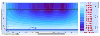
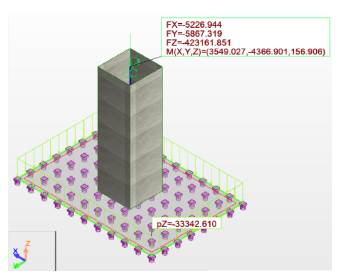
Following the traditional procedure, reactions from the superstructure are turned into actions on the substructure, in order to analyze and design the foundation system for the three soil types. The sizes of the foundations have been selected so as not to exceed the allowable stresses at the foundation level, which are represented in Figures 10 and 11 by soil type. The influence of the foundation system was checked, concluding that there was no considerable difference in stress and displacements. The foundation system was analyzed using equivalent springs for vertical displacements at the base to simulate soil elasticity (Figure 7), based on Ballast coefficient (Meli Piralla, 1986). The equivalent soil stiffness is shown in Table 1, using a finite element node spacing of 25 cm (de Macedo Wahrhaftig, 2020) (Figures 8 and 9).
Source: Authors
Figure 8 Foundation system using equivalent springs at the isolated foundation base (kN, kN.m).

Source: Authors
Figure 9 Foundation system using equivalent springs at the combined foundation base (kN, kN.m).
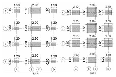


The definitive dimensions for each foundation system and for each soil type are shown in Figures 10 and 11, according to (Perez-Valcarcel, J., 2013; Garza-Vasquez, 2000; Paz, 1992).
According to Equations (1) and (2), stiffness constants for each soil type are shown in Tables 2 to 7. After calculating the equivalent spring constants, the fixed supports were replaced, thus changing structure stiffness. Please note that, on average, stiffness decreases for soils A to E, with soil A being the best, and E the worst in terms of behavior.
Analysis and design of the superstructure using equivalent springs
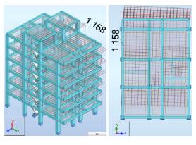
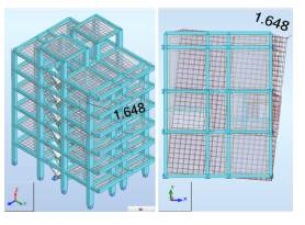
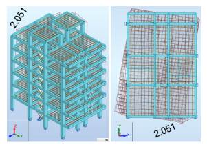
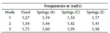
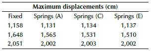
As shown in Figure 2, the fixed supports were replaced, and a new modal analysis including the new global stiffness was made. The first main comparison takes place on displacements and periods, as shown in Figures 12 to 14. Periods and displacements remained closer with the use of equivalent springs, and they were located at different points of the structure, in comparison with Figures 4 to 6, which means that foundation equivalent system reflects a similar response. On the other hand, results for frequencies and periods are shown in Tables 8 and 9, and the maximum displacements are shown in table 10 for each soil type and the first three vibrational modes. The frequencies decrease while the periods increase, as well as the maximum displacements. Additionally, the global stiffness estimate is shown in Table 11, which decreases from soil E to soil A, meaning that the stiffness is not related only to the size of the foundation system, but also to the Ballast coefficient and the type of foundation (isolated or combined).

Source: Authors
Figure 12 Maximum displacements for soil A (cm): 1st mode on the left, 2nd mode in the middle, and 3rd mode on the right.

Source: Authors
Figure 13 Maximum displacements for soil C (cm): the 1st mode on the left, the 2nd mode in the middle, and the 3rd mode on the right.

Source: Authors
Figure 14 Maximum displacements for soil E (cm): 1st mode on the left, the 2nd mode in the middle, and the 3rd mode on the right.


Comparisson between fixed models and with springs models
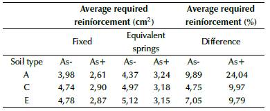
To compare the structural response among the fixed and non-fixed models, a complete design for each soil type was made. The final dimensions for the fixed structure remained the same for the non-fixed structure, in order to compare them against the reinforcement steel areas and drifts. Reinforcement steel areas for beams and columns for each model are shown in Tables 12 to 16. It can be observed that, for soil A, the required reinforcement increase is related to the stiffness, which is the highest among the three soil types, approaching to fixed model (Wahrhaftig and Brasil, 2017).


The increase in positive and negative reinforcement areas implies an increase in the maximum deflection of beams, as shown in Table 17. Please note that these increases were negligible, but, if a structural design is susceptible to deflections, the amplification must be considered, even though the increases for positive bending moments are being countered by the increase in negative bending moments, thus compensating the deflection increase. For columns, the quantities of reinforcement areas remain almost equal for each soil type, but, for all cases, there was a considerable increase associated with the new bending moments of the beams.
The direct relationship between bending moment and shear force implies an increase in shear effects; hence, a measurement of quantities of stirrups per length was established, as shown in Tables 19 and 20. Please note that stirrups quantities increase in average for beams and columns, and this is related to the increase bending moments due to gravitational effects and the reduction of the stiffness. Tables 21 and 22 show the base shear, and, for soil E, there is an amplification consistent with these results, whereas, for soils A and C, a reduction is observed while gravitational forces still increase.
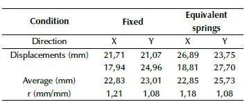
As an example, the calculation of drifts for soil E are shown in Tables 21 and 22, while the total drifts and ratios for each soil type are shown in Table 23. Ratios were calculated using Equation (10). Elastic drifts were calculated according to (NEC, 2014), which specifies that, if ratio > 1, then drifts using equivalent springs are greater than drifts using fixed supports, and vice-versa.
The procedure shown in Tables 21 and 22 was applied to all frames in both directions to obtain a global average for each structure (Table 23).
Table 21 Example for calculation of inelastic drifts for spectral Y displacements (soil E, one frame)

Source: Authors
Table 22 Example for calculation of inelastic drifts for spectral X displacements (soil E, one frame)
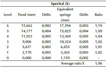
Source: Authors
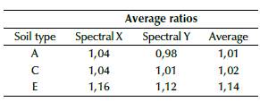
The results for drifts were as expected, which means that they were greater in models based on equivalent springs than in the fixed models. Although drifts for models with equivalent springs are greater, all models still remained within admissible values, which did not exceed the value of 0,02. Ratios increased from soil A to soil E, which is related to the global stiffness, modified due to the change from fixed supports to spring supports. Torsional irregularity was checked according to regulations and standards (FEMA, 2006, 2018; NEC, 2014), by applying Equation (8). If r ≥ 1,4, then the torsional irregularity is extreme. If 1,2 ≤ r ≤ 1,4, then the torsional irregularity must be considered in the structural analysis and design by reinforcing columns or changing their configuration or orientation. If r ≤ 1,2, then the torsional irregularity can be dismissed from the analysis. The results for torsional irregularity are shown in Tables 24 to 26.


Tables 24 to 26, show that torsional irregularity values remain admissible, and that the difference between fixed and equivalent springs models remain closer. Despite using equivalent springs, the structure still has admissible values. Additionally, the ratios for torsional moments were evaluated. Therefore, if ratio ≥ 1, then the torsional moment increases using equivalent springs and vice versa. The same equation was used to calculate ratio for base shear forces; Figure 15 shows the results for base shear forces and torsional moments for soil C.
Tables 27 to 29 show a decrease in shear forces in directions X and Y for soil A and C, although, for soil E, an increment is visible in the direction of the applied spectral forces. These results reflect that the displacements and rotations at the base using equivalent springs not only imply that the behavior of the structure changes for bad (in the form of drifts, reinforcement, or increasing torsional moments), but the spectral forces can also be reduced for each spectral load state. Table 30 shows similar results for torsional moments, decreasing for soils A and C, and increasing for soil E. These results can be attributed to the stiffness, given the fact that it decreased from soil A to E.

Conclusions
According to the results, for this regular structure, soil-structure interaction in linear range has an impact on the analysis and design. The former is related with reinforcement areas for structural elements which increased for positive and negative bending moments in all the structural models, while also increasing the quantities of stirrups per length.
Drift values showed an expected increase, being greater for soil E (14%), which was the most critical in terms of stiffness and soil resistance, as well as subjected to gravitational and seismic influences, thus allowing more displacements and rotations at the base. However, it could be enhanced by giving more stiffness to its foundation system by mechanically altering the soil properties to preserve the superstructure's cross section.
A similar response was obtained for torsional irregularity, but, in this case, it remained almost equal in terms of displacement, which is related with stiffness reduction and increasing displacements. Despite this, the torsional risk is the same, and it does not imply a significant change in the superstructure's design, so it could be enhanced by changing the substructure's stiffness.
A structure generally functions as a filter for seismic movement, that is, depending on the structure and its transfer function, it can be susceptible to the frequencies a certain earthquake. The transfer function, in turn, depends directly on the stiffness of the structure; when the structure is fixed at the base, it has more stiffness than it would with springs on it, but even so, this does not mean that the structure with springs at the base will have greater lateral displacements than the fixed structure, given that, when placing translational and rotational springs, vertical and lateral displacements and rotations will occur at the base, which can even reduce lateral displacement.
The shear forces and torsional moments increased and decreased, and so did the drifts, but the stiffness of the structure with springs decreased, which produced a reduction of shear forces in soils A and C, but increased with soil E, which is not the case for torsional moments, (it only increased for soils C and E). The explanation for this lies in the linear stiffness of the structure (translational and rotational). In the case of springs, the stiffness decreased, but the displacements increased, so there is a compensation comparable to the fixed model.
It is highly recommended to apply this study for other soil types and the same structure by optimizing the superstructure and substructure. Additonally, it is recommended to avoid displacements with higher variations at the base, which allows to control additional stresses on the superstructure.

