


 English (pdf)
 Article in xml format
 Article references
 Send this article by e-mail
 Cited by SciELO
  Cited by Google
  Similars in
SciELO
Similars in
SciELO  Similars in Google
 Permalink
Introduction
Nowadays, a wide range of applications, such as instrumentation (Wang et al., 2020, Feng et al. , 2021), physical variable measurement (Zou et al., 2016), and data transmission (Chi et al. , 2016), integrate electrical signals in the microwave and mm-wave range into their systems. Electronic oscillators have traditionally been used in telecommunications as high-frequency signal sources. However, the development of new and well-performing microwave signal generators is being boosted as a result of the emergence and evolution of some systems, e.g., radars and software-defined radio, as well as the use of higher frequencies in 5G (Ghosh et al. , 2019) and 6G cellular networks (Rappaport, Xing, Kanhere, Ju, Madanayake, Mandal, Alkhateeb and Trichopoulos, 2019). The systems based on optoelectronic components are a powerful alternative for microwave signal generation due to the high spectral purity that they can achieve (Sung et al ., 2007).
The optoelectronic oscillator (OEO) was developed in 1996 by Yao and Maleki (Yao and Maleki, 1996), and it is one of the most sophisticated mechanisms for the generation of spectrally pure microwave signals (low phase noise). One of the main advantages of the OEO architecture is its high configuration flexibility, i.e., it can be implemented in a wide variety of versions with different optical and electrical components in order to optimize its performance. In this topology, the cavity is an optical fiber delay line, and its length is related to the phase noise and the space between different non-oscillating modes. By increasing the optical fiber length, the phase noise decreases, but, at the same time, the mode spacing decreases. Multi-loop oscillators include several parallel delay lines into the cavity to guarantee an acceptable phase noise and a large mode spacing (Chen et al., 2015).
In the OEO architecture proposed by Yao and Maleki (1996), the laser source is externally modulated through an intensity modulator driven by the generated microwave signal. The VCSEL-based optoelectronic oscillator (VBO) was introduced in 2006 (Varón et al., 2006), and its architecture includes a directly modulated VCSEL. This type of laser, known for its low power consumption and low cost, is suitable for embedded aerospace applications (Rissons et al., 2012). In addition to the advantages of VCSEL lasers, the implementation of VBOs is less expensive, smaller, and requires a smaller operating current than other implementations. The VCSEL bandwidth determines the highest oscillating frequency, and some authors have achieved frequencies up to 10 GHz with phase noises of -80 dBc/Hz (Hasegawa et al., 2007) and -70 dBc/Hz (Koizumi et al., 2010) at 10 kHz from the carrier.
The frequency stability of a clock or a microwave signal can be estimated through single-sideband (SSB) phase noise and jitter measurements (IEEE, 2021). On the one hand, phase noise is a frequency domain measurement of phase deviations that allows identifying some of the noise sources within the system (Rubiola, 2008). On the other hand, jitter is the time deviation of an event (usually the rise or fall event in digital systems and clocks) from an ideal reference time frame or sampling point (Da Dalt and Sheikholeslami, 2018). In digital transmission systems, increasing transfer rates are limited by mistiming in regeneration processes (Ryu et al., 2020). For this reason, ultra-low jitter clocks must be implemented to meet the tolerance ranges of transmitting and receiving equipment (Choi et al., 2019).
Some transmission systems such as optical transport networks (OTN) and Gigabit Ethernet networks include precise specifications regarding jitter tolerance and frequency accuracy (ITU, 2018). In this way, the application of an optoelectronic oscillator in a digital data transmission system can be established through jitter and phase noise measurements. As a contribution to this field, we present the first timing-jitter analysis for a VCSEL-based optoelectronic oscillator. The VBO implementation of this work uses the latest generation of VCSELs in the O and C-bands with reduced relative intensity noise (RIN) in comparison to VCSELs used in previous publications (Varón et al., 2006; Rissons et al., 2012; Koizumi et al., 2009).
This paper is structured as follows: the first section comprises a detailed VCSEL description and an experimental laser characterization for both VCSELs used; then, the VBO architecture is described, and a phase noise predictive model is presented; the VBO implementation, in terms of phase noise and timing-jitter, is addressed in a third section; some performance comparisons between our systems and previous VBO implementations available in the literature are detailed in the fourth section; and, finally, the last section presents some conclusions about our work.
Vertical-cavity surface-emitting lasers -VCSEL
The vertical-cavity surface-emitting lasers are semiconductor lasers widely used in telecommunications at high transfer rates through different modulation formats, such as direct modulation (Malacarne et al., 2017), discrete multitone modulation (DMT) (Wagner et al., 2017) and four-level pulse amplitude modulation (PAM-4)(Lavernick et al., 2017). While multimode VCSELs at short-wavelengths (850 - 1 050 nm) are employed in short-reach fiber links (Pavan, Lavrencik and Ralph, 2017) and visible light transmissions (Li-Fi) at 680 nm (Lu et al., 2017), long-wavelength VCSELs (LW-VCSEL) in the 1,2 -1,6 ym range, are used in long-haul communications (Bacou et al. , 2010).
The development of LW-VCSELs has evolved in recent years according to their requirements and applications. Wafer-fused LW-VCSEL technology is the most applied for VCSEL manufacturing, covering the entire ITU-T single-mode spectral range (1 260 nm - 1 675 nm). The main drawback of this technology is the integration of the active region (which requires high optical gain) with the mirrors (high-reflectivity, low optical absorption, and high thermal conductivity) in a monolithic semiconductor (Belkin et al ., 2015).
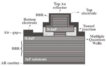
VCSEL manufacturing has three particularities. First, the active cavity is grown on an InP substrate and incorporates InAlGaAs quantum wells (QW) covering both bands (Syrbu et al., 2005). Secondly, the top and bottom AlGaAs/GaAs distributed Bragg reflectors (DBRs) are bonded to the active cavity using localized wafer fusion (lakovlev et al., 2005). This approach avoids VCSEL overheating problems. Finally, tunnel junctions (TJ) are grown to reduce free carrier absorption and mirror optical loss, as well as to ensure a single-mode transverse emission (Belkin et al., 2015).
The O and C-band VCSELs used for this work were produced by the Korean manufacturer RayCan, and their structure is depicted in Figure 1 . All layers were epitaxially grown by metal-organic chemical vapor deposition (MOCVD) on InP substrate (Park et al., 2006). Each laser was placed inside a TO-56 package, and its output beam was coupled to a single-mode optical fiber.
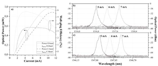
The optical power versus bias current for both VCSELs is presented in Figure 2. The maximum emission powers of O and C-band VCSELs are 0,97 mW and 0,89 mW when the bias currents are 10,3 mA and 11,1 mA, respectively. The reduced threshold currents are close to each other (1 mA for O-band and 1,5 mA for C-band) and represent 10% of the current for a distributed feedback laser (DFB).
Source: Authors
Figure 2 a) Bias current vs. output power and wall-plug efficiency (optical spectra at 5, 6 and 7; mA b) O-band c) C-band VCSEL)
The selected bias current for the VBO implementations was 6 mA, given the linearity in this region, the constant wall-plug efficiency (WPE) after 4 mA, and the linear behavior of the dynamic resistance. Figure 2 shows the single-mode operation of VCSELs at different bias current and wavelengths around 1,31 μm and 1,54 μm.
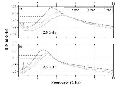
Another relevant parameter for the VBO implementation is the relative intensity noise (RIN) due to its influence on the oscillator phase noise. RIN is expressed in dB/Hz and relates the photon density fluctuation to the mean photon square density. RIN measurements at 25 C for both VCSELs are shown in Figure 3. Regardless of the optical band, the RlN decreases when the bias current increases, since the stimulated emission is higher than the spontaneous one when the bias current moves away from the threshold current. Under the same conditions, and considering the RIN values at 2,5 GHz, the RIN is slightly lower in the O-band VCSEL for all bias currents. The RIN values for 5, 6 and 7 mA are -141, -144 and -146,5 dB/Hz, respectively, whereas, for the C-band VCSEL, they are -138, -142 and -143 dB/Hz. Considering the experimental results and the measurement uncertainty, both lasers impact the phase noise in the same proportion.
VCSEL-based optoelectronic oscillator
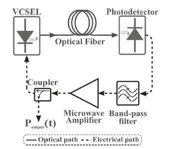
The VCSEL-based optoelectronic oscillator (VBO), which is illustrated in Figure 4, is a self-seeding ring oscillator composed of a directly modulated VCSEL that passes through a low-loss glass fiber, which acts as an optical delay line. Owing to the lower attenuation, long cavity length and a high-quality factor Q are possible, thus allowing low phase noise. Then, the optical signal is converted to the electrical domain by a photodetector. The electrical signal is amplified by a microwave amplifier to compensate loop losses and then filtered by a band-pass filter to select the oscillation frequency and remove the spur modes. Finally, the loop is closed using an electrical coupler, which allows extracting the generated microwave signal (Hayat et al., 2008).
The selectivity of the oscillation mode will depend on the resonant element through the optical delay Td produced by the optical fiber. The quality factor for the VBO is directly proportional to the optical fiber length, and it is expressed as follows:
The oscillation mode is selected from the optical fiber frequency comb by the microwave band-pass filter. The mode spacing in the optical fiber is defined as the free spectral range (FSR), which is expressed as:
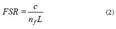
where, c is the speed of light, nf is the refractive index of the optical fiber core, and L is the optical fiber length. The longer the optical fiber, the closer the optical fiber oscillation modes. The selected mode lies inside the microwave filter band-pass bandwidth.
VBO phase noise is related to the phase fluctuation propagation of optical and electrical components inside the loop. By using Rubiola's linear feedback approach for delay-line oscillators (2008), the power spectral density (PSD) of phase fluctuations SΦ (s) can be expressed as follows:
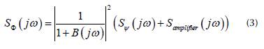
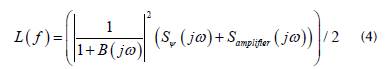
where B(jω) is the transfer function of the resonator and the delay line, Sψ(jω) is the noise power spectral density due to components, and Samplifier(jω) the microwave amplifier noise. The main noise contributions from the components are the phase variation in the optical fiber, the thermal and shot noise, and the relative intensity noise of VCSELs. By definition, phase noise is the half of the one-sided PSD of phase fluctuations (IEEE, 2009); thus, the VBO phase noise L( f ) can be expressed as follows:
Another useful metric to verify frequency stability is timing-jitter, which corresponds to the short-term temporal variations of a signal relative to an ideal signal (lnternational Telecommunication Union (ITU), 1996). Although phase noise is a frequency domain measurement and jitter is a time-domain measurement, both are related through Equation (5) (Da Dalt and Sheikholeslami, 2018):
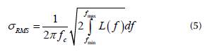
where σRMS corresponds to the root mean squared (RMS) jitter, fc is the oscillation frequency, and fmin and fmax are the lower and upper frequency of the phase noise measurement, respectively. Jitter measurements can be composed of two individual contributions: random and deterministic jitter. On the one hand, random jitter (RJ) is caused by uncorrelated noise, e.g., thermal noise. Moreover, it generally follows a normal or Gaussian distribution. On the other hand, deterministic jitter (DJ) comes from systematic effects (intersymbol interference (ISI) and periodic jitter), and it can be predicted and reduced.
2,5-GHz VCSEL-based optoelectronic oscillator characterization
Setup description
Several VBOs at 2,5 GHz using 1,31 urn and 1,54 pm VCSELs were implemented and characterized through phase noise and jitter measurements. As stated before, the goal of using a direct modulated VCSEL is to develop a high spectral purity oscillator with low power consumption. For this oscillator, a cavity band-pass filter centered at 2,5 GHz, 3 MHz bandwidth at 3 dB, and insertion losses lower than 3 dB is used. A 39 dB gain low noise microwave amplifier is used to amplify the selected mode. The amplifier output is connected to a tunable attenuator in order to control the closed-loop gain, and the output is then connected to a bias tee to modulate the optical source.
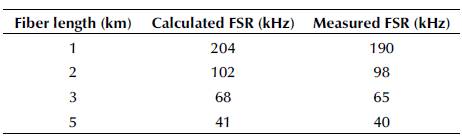
The optical fiber length is varied from 1 to 5 km in order to evaluate its effects on spectral purity and jitter variations. The measured and calculated FSR for each length are presented in Table 1. Although a higher Q factor guarantees lower phase noise values, the reduced FSR can directly impact some sensitive parameters for telecommunications applications, such as jitter and residual phase modulation (PM), through the contribution of each non-oscillating mode.
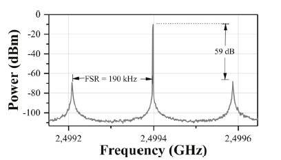
Electrical output spectrum
Figure 5 shows the electrical spectrum taken from a 20-dB coupler output for 1 km. The measured FSR is 190 kHz, and the difference with the theoretical value corresponds to the fiber length uncertainty and the delay contribution of the electronic components. The oscillation power is -10 dBm, and the side mode suppression ratio (SMSR) to the first non-oscillating mode is 59 dB. The oscillation power can be improved by using an electrical coupler with a less attenuated output.
Phase noise characterization
The phase noise measurements for each VBO configuration are taken using a direct measurement method through an electrical spectrum analyzer ESA (R&S FSW50). For measurement validation purposes, a calibrated phase noise signal is implemented through frequency modulation (FM) of an ultra-low phase noise source (at 2,5GHz) with uniform noise (Gheen, 2012). According to the difference between the technical specifications of the ultra-low phase noise source and the phase noise measurements, the lowest of the latter, using direct method, is limited to -130 dBc/Hz at 10 kHz from the carrier.
Figure 6 shows the phase noise curves of the implemented VBOs using O and C-band VCSELs. In both cases, the phase noise is improved when the optical fiber delay line is enlarged, i.e., when the quality factor of the resonator is increased.
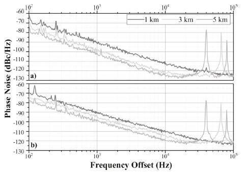
Additionally, the phase noise level difference between the optical bands is given by the zero chromatic dispersion of the standard single-mode optical fiber employed at 1,3 μm. In this sense, the lowest phase noise values are achieved when a O-band VCSEL is used.
Regardless the optical fiber length, two noise processes are identified in the phase noise curves. The white phase noise process is located far from the carrier (from 20 kHz), and it is produced mainly by the white noise of the microwave amplifier. On the other hand, the white frequency noise process varies at a -20 dB/decade rate, and it results in the up-conversion process (also called Leeson effect) from the flicker noise of the amplifier inside the loop (Guo et al., 2018). For the O-band VCSEL, white frequency noise is present in the two first decades (from 100 Hz to 10 kHz); for the C-band, the same slope is located only from 2 kHz to 10 kHz. In this decade, the slope becomes -25 dB/decade due to a more significant RIN contribution in this band.
Timing-jitter characterization
For the phase noise curves using 3 and 5 km, the sharp peaks are spaced at 65 and 40 kHz, respectively. These values correspond to the FSR values summarized in Table 1. The frequency comb peaks are close to each other and cannot be rejected by the microwave band-pass filter. Consequently, these non-rejected peaks become secondary oscillation modes that can increase the timing-jitter. Figure 7 depicts the histograms (10 000 samples) of the time interval error (TIE) measurement using an O-band VCSEL and diferent fiber lengths.
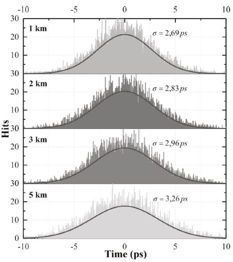
According to Table 2, and under the same conditions, the lowest phase noises and jitters are obtained using O-band VCSELs. This efect is mainly due to the zero-dispersion of the fiber at wavelengths close to 1,3 μm and the level power inside the loop. For both lasers, the phase noise improves proportionally when the resonator length increases, but, at the same time, the jitter deteriorates. Although the peak-to-peak jitter increases from 71 to 106 mUI, in any case, the values exceed the specifications of local clocks for OTN networks defined by the recommendation ITU-T G.8251 (ITU, 2018).
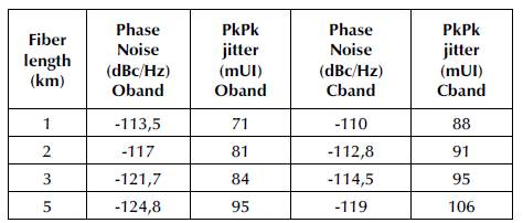
In all cases, the histograms show a dominant Gaussian behavior, i.e., the main contribution comes from random jitter. The TIE RMS jitter was determined through the standard deviation of the Gaussian distribution of each histogram. Contrary to what was expected, the TIE RMS jitter increases as the fiber length increases. This phenomenon has two reasons. Firstly, the new non-rejected modes expand the profile of the Gaussian distribution due to additional periodic jitter. Secondly, the amplifier input power decreases due to the higher optical attenuation, and, consequently, the white noise contribution of the amplifier is stronger. One way to reduce this effect is to use a band-pass filter with narrower bandwidth, therefore reducing the contribution of periodic jitter of each mode. Table 2 summarizes the measured phase noise at 10 kHz of set and the peak-to-peak jitter expressed in unit interval (UI) for each case.
Phase noise model validation
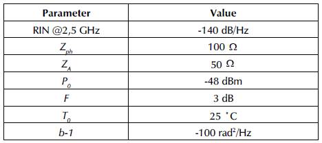
The linear model of Equation 4 allows estimating the phase noise of the VBO considering diferent noise sources. The transfer function B(jω) is determined using the Laplace transform to the phase impulse response of the optical delay (Bd(jω) = e-jωτd ) and the microwave filter (Bf (jω) = 1/(1 + jωτf )), where τf is the filter group delay. The noise power spectral density Sψ(jω) referred to the input impedance of the amplifier (ZA) includes all the additive noise sources inside the loop (VCSEL RIN at the oscillating frequency RINVCSEL, shot and thermal noise, and the intensity-to-phase noise conversion process due to Rayleigh scattering RINfiber). Sψ(jω) can be expressed as:
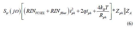
where i ph is the photodetected current, k B is the Boltzman constant, T is the operating temperature, and Z ph is the photodetector impedance. The power spectral density of the microwave amplifier S amplifier (f) involves white noise and flicker noise (Rubiola, 2008). The white noise component is estimated from the equivalent noise spectral density (N = FkT 0 ) and the carrier power P0 at the amplifier input (Rubiola and Giordano, 2007). In contrast, flicker noise is independent of carrier power at the amplifier input over a wide frequency range. Hence, S ampljfjcr (f) corresponds to:
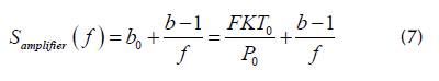
where b-1 is a constant coefficient of flicker noise, F is the noise figure, and kT 0 is the thermal energy.
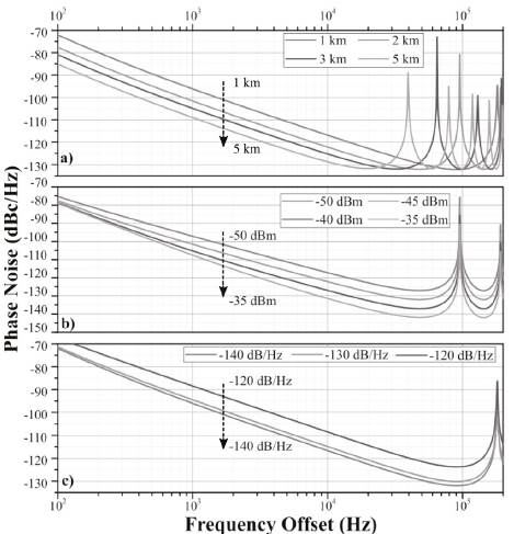
Figure 8 presents the estimated phase noise curves using the electrical power P0, which was experimentally obtained, and the technical characteristics of loop components summarized in Table 3. Figure 8a presents the estimated phase noise when the fiber length is 1, 2, 3, and 5 km, and the amplifier input power is constant. The phase noise at 10 kHz offset is reduced by 12 dB from -116,8 dBc/Hz to -128 dBc/Hz when the length is 1 km and 5 km, respectively. The estimated phase noise curves when P0 ranges from -50 dBm to -35 dBm are plotted in Figure 8b. As expected, the input power modified the floor phase noise and the noise level far from the carrier. Therefore, the phase noise at 10 kHz from the carrier is improved by 14 dB (from -117,2 dBc/ Hz to -131,5 dBc/Hz). The noise close to the carrier is also reduced, but it is limited by the additive noise sources and the flicker noise coming from the microwave amplifier. The level diference between the estimated and measured phase noise is caused by measurement uncertainty (around 3 dB for the direct method) and because some parameters are assumed from the literature.
Source: Authors
Figure 8. Phase noise simulation using different a) optical fiber lengths, b) amplifier input powers, and c) RIN values
The effect of the VCSEL RIN on the phase noise is represented in Figure 8c by assuming three different noise values: -120, -130, and -140 dB/Hz. For values below -130 dB/Hz, the phase noise at 10 kHz from the carrier is slightly enhanced (2 dB better when RIN = -140 dB/Hz). Conversely, when the RIN is -120 dB/Hz, the phase noise deteriorates rapidly by 8 dB from the value obtained for RIN = -130 dB/Hz (-116,64 dBc/Hz).
In all cases, the oscillating frequency is limited by the bandwidth laser and the electrical access. At 2,49 GHz, the highest phase noise is -100 dBc/Hz, and it was obtained when a multimode VCSEL emitting at 0,85 ym and 120-m optical fiber were employed. Despite the reduced RIN of the multimode VCSEL (-130 dB/Hz), the phase noise of the VBO was deteriorated by the high attenuation and the reduced Q-factor provided by the multimode optical fiber.
The RMS jitter can be also estimated by employing Equation 5 and the phase noise curves plotted in Figure 8a. By lengthening the optical fiber from 1 to 5 km, the RMS jitter is reduced from 1,37 ps to 0,33 ps, respectively. The diference between the estimated RMS jitter and the TIE jitter measurements is given by the aliasing and the noise floor of the oscilloscope used for the measurements.
Performance comparison
Table 4 presents some phase noise results obtained by diferent authors using short and long-wavelength VCSELs.
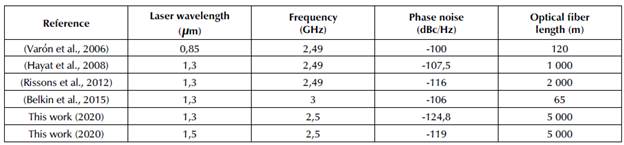
When long-wavelength VCSELs are used, the phase noise of the generated microwave signal is improved in all cases. This event is mainly attributed to the RIN reduction resulting from the technological advances in VCSEL manufacturing, as well as the lengthening of single-mode optical fiber.
The lowest phase noise values of our work were obtained when the optical fiber length was 5 km. The phase noises were -124,8 dBc/Hz and -119 dBc/Hz when the emitting wavelengths were in the O and C-bands, respectively. To the best of our knowledge, these values are the lowest reported in the bibliography at 2,5 GHz when direct modulation is applied. According to the numerical results presented in the previous section and the experimental results (Table 4), we attribute the phase noise improvement to the reduction of the white phase noise through the amplifier input power P0, and the lengthening of the optical fiber.
Conclusions
This paper presents the first time-domain stability characterization of several VBO implementations by performing timing-jitter measurements and their frequency-domain stability through phase noise measurements. As stated, both stability measurements are frequently used for establishing clock accuracy for several data transmission systems.
For all the experimental validations, the last generation of O and C-band VCSELs with reduced RIN levels were employed. In this way, VCSEL RIN and longer optical fiber have improved the phase noise by 8 dB in comparison with previously reported results. The best phase noise performance measured at 10 kHz from the carrier was -124,8 dBc/Hz, and it corresponds to the lowest value reported in the literature for a 2,5 GHz-VBO. It was experimentally demonstrated that the longer the optical fiber, the better the spectral purity, but, at the same time, the worse the timing-jitter deterioration. According to the application, a trade-of must be made between phase noise and timing-jitter.
Given the higher contribution from the non-oscillation modes, the peak-to-peak jitter increases from 71 to 106 mUI when the optical fiber length is enlarged from 1 to 5 km. In all cases, the electrical output of the VBO can be used as a recovery clock that meets the jitter tolerances of ITU-T G.813 for STM-16 transmissions and Telcordia GR- 253-CORE for OC-48 transmissions.
The phase noise estimation model agrees with the experimental characterization of the far-from-the-carrier microwave signal. The model can be improved by a complete characterization of the microwave amplifier and the addition of multiplicative noise sources such as the frequency noise and the low-frequency RIN of the VCSEL.
Considering the good phase noise performance and its lower power consumption, the VBO is suitable for embedded applications and an all-integrated solution can be explored. Additionally, high-bandwidth on-chip VCSELs can be employed to increase the oscillating frequency.
For future developments, it is recommended to employ other resonant elements such as fiber ring resonators, whispering gallery modes, or double feedback loop oscillator in order to explore the spectral purity performance in the frequency domain. A stability analysis in the time domain (long-term stability) is proposed, which uses a deviation.high-resolution frequency counter and the Allan standard deviation.

