


 Inglés (pdf)
 Articulo en XML
 Referencias del artículo
 Enviar articulo por email
 Citado por SciELO
  Citado por Google
  Similares en
SciELO
Similares en
SciELO  Similares en Google
 Permalink
Introduction
Masonry walls are of widespread use due to the availability of the materials needed to build them, along with their quick and cost-effective construction. Particularly in Mexico, 87% of the dwellings are built using masonry walls (INEGI, n.d.), wherein many cases are confined masonry walls. These types of walls are built using unreinforced masonry and reinforced concrete (RC), i.e., tie-columns and bond-beams. Tie-columns and bond-beams provide confinement on the plane of the wall panels and reduce the out-of-plane bending effects. Furthermore, unreinforced masonry is constructed out of different masonry units, such as hollow clay/ concrete and solid clay/concrete units. In order to provide confinement to the masonry units, the spacing of the tie-columns must be less than 4 m or 1,5 times the wall height, and their thickness must be more than 100 mm and not less than the width of the masonry unit (Rodríguez, 2009).
Previous research has focused on the effect of ties and stirrups on the behavior of columns and beams as isolated structural elements (Gribniak et al., 2017; Hong et al., 2006; Salah-Eldin et al., 2019; Tan et al., 2018). In this line of research, unconventional geometries of ties and stirrups for these structural elements have been studied mainly on beams (Lima de Resende et al., 2016; Pérez-Caldentey et al., 2013). In the study conducted by de Corte and Boel (2013), spiral shear reinforcement was used on the beams. Colajanni et al., 2014 also employed stirrups with different inclinations. Other authors have focused on the behavior of beams without stirrups (Arslan, 2012; Azam et al., 2016; Ridha et al., 2018). Other studies (Du et al., 2017; GrgiC et al., 2017; Li et al., 2018; L. Sun and Li, 2019) were conducted for ties in columns. Dong et al. (2018) proposed an innovative winding glass fiber-reinforced polymer tie (closed loop type). However, none of these studies have focused on the behavior of stirrups for tie-columns or bond-beams.
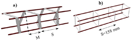
In this article, a new type of tie, denoted as a strapping spiral tie (SST), is studied. A company located in Monterrey, Mexico (Aceros-Titán-Company, 2016), patented the manufacturing process to produce this type of tie. The main advantages of using it are the reduction of labor cost and the increase in the speed of reinforcement placement (de Corte and Boel, 2013). SSTs can be produced with different spacings (Figure 1). The steel strips are produced using a cold formed method, which changes their mechanical properties (Yun and Gardner, 2017).
The aim of this research was to evaluate the behavior of SSTs in short tie-columns, along with their confinement capacity, and to provide a comparison between SSTs and traditional ties. This was achieved by means of experimental tests and a micro-numerical model. In order to achieve these goals, the next section describes the experimental design, materials, and tests along with the numerical model employed. Later, results and discussions are presented with regard to (1) the validation procedure, (2) the compressive strength comparison between traditional ties and SSTs, and (3) the behavior of SSTs. Finally, conclusions are drawn.
Materials and methods
Experimental design for the specimens
For this study, 12 specimens of short tie-columns were fabricated. These specimens have ties with different spacings, which are specified in Table 1. According to the standards (ACI International, 2013; NTCM, 2017), tie spacing must be less than 200 mm or 1,5 times the thickness of the masonry unit. Three different values of spacing were considered (Table 1): (1) 200 mm, i.e., the maximum spacing allowed; (2) 120 mm as the minimum, considering a minimum brick thickness of 80 mm; and (3) a spacing of 158 mm. The latter is the most widely used spacing by bricklayers in the region. From this point forward, the tie spacing will be identified through the machine spacing M, i.e., the configuration on the machine that makes the straps (Figure 1). That is to say, 3, 3,95, and 5 cm long (Table 1).
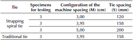
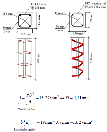
Table 1 presents the number of specimens for each spacing and type of tie tested. Two types of ties were studied: traditional and SST. To characterize the specimens and validate their numerical models, three samples were tested for each type and spacing. Figure 6 shows their geometry.
Material tests
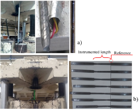
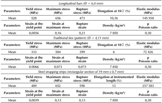
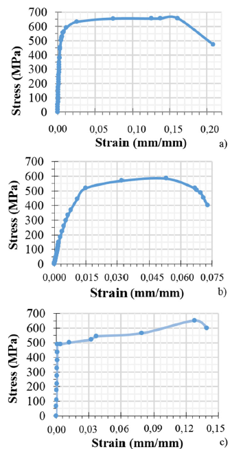
The characterization of the mechanical properties of the reinforcement steel were determined through uniaxial tensile tests, in accordance with ASTM standards (ASTM International, 2009, 2019). In addition, compression tests were conducted on concrete specimens (ASTM International, 2015, 2018). For the reinforcing steel, eight samples of the traditional ties and longitudinal bars (Figure 2a) and seven samples of the steel strapping strips with a characteristic length of 10 cm (Figure 2b) were tested in order to obtain their stress-strain curves. The elastic modulus was obtained by applying Equation (1), according to ASTM-A370 (ASTM International, 2019). Table 2 shows the average values of the elastoplastic parameters obtained for the longitudinal bars, traditional ties, and steel strapping strips. The stress-strain curves obtained are presented in Figure 3.
Source: Authors
Figure 2 (a) Steel bars testing; (b) strapping strip test, using an electric displacement transducer and SST after testing
Source: Authors
Figure 3 Stress-strain averaged curves for: a) longitudinal bars, b) traditional ties, c) strapping strips
where E → Elastic modulus; σ f → Yield stress; and ε f → Yield strain.
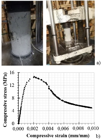
To characterize the mechanical properties of the concrete, axial compression tests of 27 samples were carried out (Figure 4a) at 28 days. An average strength of
 = 15 MPa was attained, with a coefficient of variation of δ = 0,0845. The cement used was CPC (Composite Portland Cement), with a maximum coarse aggregate size of 1/2 in (12,7 mm). Strain gauges were used to obtain the loading branch, while multiple linear variable differential transformers (LVDTs) were used to capture the unloading branch. Figure 4b shows the experimental results that will be introduced in the numerical model.
Specimen testing
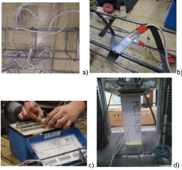
The structural response of reinforced concrete specimens is conditioned by the mechanical properties of their constituent components: steel and concrete. To characterize their behavior, strain gauges and LVDTs were used (Figure 5). The dimensions of the short specimens were selected to avoid lateral instability problems and were 500 x 150 x 150 mm (length x height x thickness). All the SST specimens had ties with a cross-sectional area equal to the traditional tie area (Figure 6).
Source: Authors
Figure 5 Instrumentation with strain gauges: a) longitudinal bars and traditional tie instrumentation, b) SST instrumentation, c) data acquisition device, d) specimen ready to be tested
The specimens were tested using an electro-hydraulic press (Tinius Olsen brand). These tests were performed with displacement speed control (0,005 mm/s) in order to obtain their post-peak behavior. In order to achieve a uniform load distribution on the top and bottom faces, 25 mm thick steel plates were placed (Figure 5d).
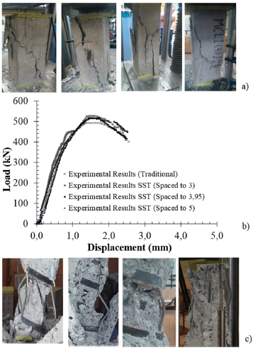
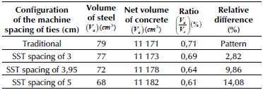
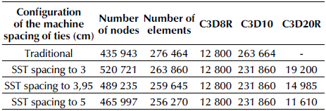
Sliding of concrete was the observed mode of failure (Figure 7a), along with buckling of the longitudinal bars (Figure 7c). For structural columns (ACI International, 2014), this implies structural collapse. However, for tie-columns, the wall would be able to stay up. This mode of failure is attributed to the use of a minimum transversal reinforcement area in the specimen. In addition, Figure 7b shows the averaged load-displacement's experimental results for the specimens. Furthermore, volumetric steel-concrete ratios for all the tested specimens, along with the percentage of reduction of the steel ratio for each set of SSTs, are presented in Table 3. It is noteworthy that, for a SST spacing of 5 cm, a significant reduction of 14,08% is observed.
Source: Authors
Figure 7 (a) Failure mode of the specimens, (b) averaged load-displacement experimental results, (c) loss of stability of the longitudinal bars
Numerical simulation
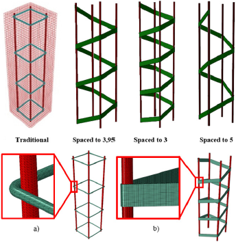
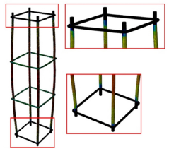
To obtain a higher level of computational precision, the three-dimensional micro-modeling technique was employed for the structural analysis of the four types of short tie-columns (Table 1 and Figure 8). The geometry of the steel bars and strips was modeled independently of the concrete matrix, with their corresponding constitutive laws (stress-strain curves). The ABAQUS/Explicit environment (Abaqus, 2016) was employed to carry out the simulations. The required integrations were performed by the well-known central difference integration scheme. Details of the mathematical modeling are provided in the following sections.
Geometry, element types, and mesh
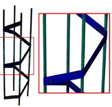
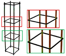
For the mathematical calibration, a finite element (FE) formulation, appropriate mesh size, and shape were considered (Mesa and Alvarez, 2011). Three-dimensional hexahedral elements C3D8R (eight contact nodes, reduced integration, and Hourglass control) were used for modeling the concrete matrix. For the longitudinal bars and traditional ties (Figure 8a), three-dimensional tetrahedral elements C3D10 (10 quadratic contact nodes) were employed. The SSTs (Figure 8b) were modeled with three-dimensional hexahedral elements C3D20R (20 quadratic nodes and reduced integration). The concrete and steel bonding zones were modeled using a contact surface. Table 4 shows the meshing used for the four three-dimensional models.
Boundary and loading conditions
The boundary conditions defined for the mathematical model are consistent with the support conditions of the experimental physical model. In other words, a uniform displacement of the top face is allowed only in the loading direction, and, at the bottom face, the movement is restricted for all the degrees of freedom. In addition, the mathematical model was subjected to a quasi-static load model by considering a displacement control of the top face, which was implemented by means of an explicit step function with soft amplitude. As a convergence criterion, a limit value of 5% was adopted for the ratio of kinetic energy and total internal energy (Fei et al., 2017).
Constitutive laws
A concrete damaged plasticity model (CDPM) was used to define the nonlinear behavior of the concrete. A CDPM can simulate a quasi-brittle material behavior for both concrete and masonry, as well as the two main failure mechanisms of concrete: tensile cracking and compressive crushing. It is based on the basic models proposed by Lubliner et al. (1989) and improved by Lee and Gregory (1998) by considering the separation of damaged plasticity and the behavior of concrete under uniaxial tensile and compressive stresses.
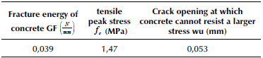
The stress-strain relationship, under tensile stress, is linear-elastic up to the point where the peak tensile stress is reached. After that, the softening tensile behavior is modeled by stresscracking strain or by considering fracture strain energy. Table 5 shows the cracking displacement when the complete loss of strength is attained (C. T. Sun and Jin, 2012; Telford, 2010). In this table, G f is the fracture energy that represents the strain energy required to open a unit area crack, and f c describes the tensile peak stress, as expressed in Equation (2).
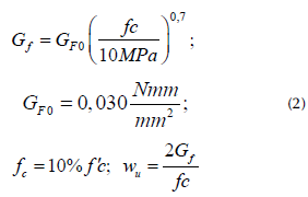
Where: G f → Fracture energy, f c → tensile peak stress, and w u → crack opening at which concrete cannot resist larger stresses.
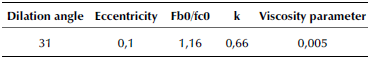
The following inelastic parameters were defined in order to determine the yield surface shape and the flow potential surface (Druker-Prager hyperbolic function): (1) a dilation angle; (2) flow potential eccentricity; (3) ( f bo / f co ) , which represents the equi-biaxial/uniaxial compressive yield stress ratios; (4) K c , the second stress invariant on tensile meridian vs. compressive meridian ratio; and (5) viscosity. The K c value has influence on the yield surface shape (Sümer and Aktas, 2015).
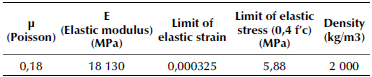
Table 6 shows the values employed for these five parameters. The viscosity provides a quick convergence, as it allows a way to overcome the yielding zone as per the CDPM parameters. The viscosity value is fitted by trial and error. The Hill elastic plastic model (Caminero and Montans, 2010) was employed for a longitudinal and transversal steel constitutive ratio, with nonlinearity and hardening isotropy. The elastic parameters of concrete are defined in Table 7 (Telford, 2010).
Results and discussion
Validation procedure
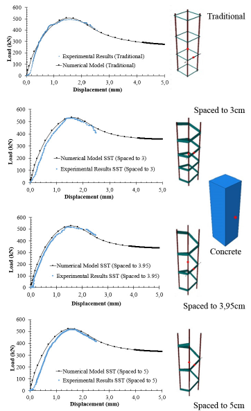
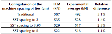
The experimental results of each specimen were obtained from the displacement-controlled test. Moreover, their corresponding load-displacement curves (LDC) were obtained from the numerical simulations. To validate the numerical model, the experimental results were compared to LDC. Figure 9 illustrates the averaged experimental results obtained from the specimens, along with the curves obtained from the numerical models (i.e., LDC). The four models show a satisfactory fit. Table 8 shows a small relative difference (less than 5%) at maximum load.
Source: Authors
Figure 9 Load-displacement curves comparison between experimental results, and numerical models with location points where the strain gauges were placed in longitudinal steel, traditional ties, SST, and concrete
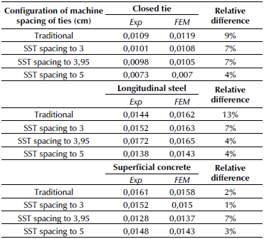
During the validation process, strains measured by strain gauges in longitudinal bars, traditional ties, SST, and concrete (Figure 9) were compared to the strains from the numerical simulations (Table 9). The relative differences between these values were less than 13%. Thus, the numerical model is suitable to analyze SST, taking the different spacings into account.
Load-displacement curves comparison
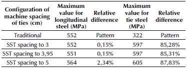
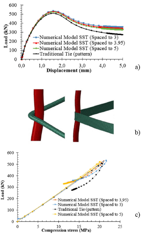
It is well known that the longitudinal steel ratio is more meaningful than the transversal steel ratio on the compressive axial behavior of reinforced concrete. When using SSTs, a slight increment is observed in the compressive strength of the elements, in conjunction with a reduction in steel volume regarding the experimental results and FE models. This, despite the lower steel ratio in specimens with respect to traditional ties (Figure 10a and Table 10). On the other hand, Tables 10 and 11 imply that the rupture failure of the steel did not take place in the longitudinal bars, nor in the transversal steel. The variation of the von Mises stress in longitudinal bars is not significant, while the stress distribution in ties shows a relative difference of 88% when the maximum load is reached (Table 11), and 40% when the maximum displacement is reached (Table 12).
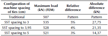
Table 11 Von Mises criteria for longitudinal steel and ties when maximum load is reached
Source: Authors
SST behavior
SST provides a greater confinement to the concrete specimens when compared to traditional ties, given the larger contact area against concrete (Figure 10b). The degree of confinement was obtained by measuring the compressive stress at the center of mass of each model. Figure 10c shows that, at unloading, the compressive stress decreases more rapidly with traditional ties than with SST. This leads to better behavior and stability of the SST. This means that the traditional tie has more softening than the other ties in the center of mass of the concrete in the post-peak stage, which in turn implies a decrease in its confinement capacity in comparison with the other models. By comparing the last point in the curve of Figure 10c, the next ordered pairs are obtained (load, compressive stress): Traditional (277 kN, 13,2 MPa); SST spacing 3 (357 kN, 13,3 MPa); SST spacing 3,95 (344 kN, 12,2 MPa); and SST spacing 5 (335 kN, 11,70 MPa). This indicates a relative difference of -29% for SST spacing set to 3 cm, -24% with SST spacing set at 3,95 cm, and 21% when a SST spacing of 5 cm is employed. These results imply a better confinement for concrete in all scenarios. In this computation, the control value corresponds to the traditional ties. Additionally, the compressive stress levels in the central mass of the concrete have the following relative differences: 11,4, 7,6, and -0,8% for 5, 3,95, and 3 SST spacings, respectively.
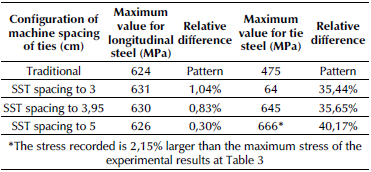
Table 12 Von Mises criteria for longitudinal steel and ties when maximum displacement is reached
Source: Authors
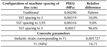
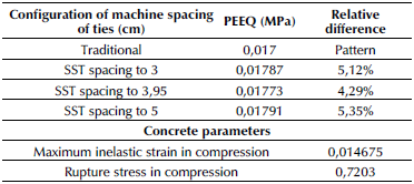
When the maximum compressive strength is achieved, the yielding of steel is in its initial stage in the longitudinal bars, as well as in the SST (Table 2 and Figure 11). However, in traditional ties, yielding has not started yet (Table 2 and Figure 12). At this stage, concrete is in its softening zone (Table 13), i.e., the post-peak stage. Traditional ties have already attained yielding when the maximum displacement is reached (Figure 13), and concrete has already exceeded the plastic strain (Table 14).
Table 13 Maximum plastic equivalent strain (PEEQ) when the model reaches maximum load
Source: Authors
Source: Authors
Figure 11 Yielding of the SST spacing of 5 when maximum load is attained. Black represents the yielded zone.
Source: Authors
Figure 12 Yielding of the traditional ties (pattern) when maximum load is reached. Black represents the non-yielded zone. In this case, none of the ties reaches yielding.
Table 14 Maximum plastic equivalent strain (PEEQ) when the model reaches maximum displacement
Source: Authors
Conclusions
In this paper, three-dimensional micro-numerical models were developed to analyze the behavior of RC short tie-columns. At the same time, FE models were calibrated and validated. Quadratic elements C3D20R and C3D10 were employed for steel modeling with circular cross-sections and strapping steel, respectively. Moreover, linear elements C3D8R were used to model concrete. At this stage, the following conclusions can be drawn when comparing SSTs and traditional ties:
An increase of 21% in the concrete confinement was attained in the unloading curve inside the elements (Figure 10c). This is due to a larger exposed contact area between steel and concrete. Once the maximum compressive strength of short tie-columns is reached, the loss of stiffness is lower in comparison with traditional ties.
The volume of steel is reduced. Table 3 shows a 14% of relative volume difference when the SST spacing is 5 cm, against traditional ties. This provides a significant reduction in the cost of raw materials for manufacturing these ties. Furthermore, the manufacturing time is also significantly reduced.
The SSTs with the spacings of 3, 3,95, and 5 cm offered a slight increase in compressive strength for short tie-columns when compared to traditional ties. However, due to large confinement and the reduction of labor costs, along with the speed of the reinforcement placing, this makes it a better option for reinforcement.
For future research, we recommend the inclusion of different steel ratios in flexural elements and larger tie-columns, as well as masonry walls.

