


 Inglés (pdf)
 Articulo en XML
 Referencias del artículo
 Enviar articulo por email
 Citado por SciELO
  Citado por Google
  Similares en
SciELO
Similares en
SciELO  Similares en Google
 Permalink
Introduction
Tunnel infrastructure is a fundamental part of modern life, as it reduces the impact on the surface and improves travel times. Research on tunnel design and construction continues, given the large amount of data, knowledge, and expertise that are required for these civil works. In practice, many methods are used in the design phase, such as empirical, analytical, and numerical analysis. Empirical methods have used equations based on experience (Khan et al., 2019; Rehman et al., 2018; Terzaghi, 1942), analytic methods use rupture schemas to emulate soil or rock failure (Lu et al., 2020; Kong et al., 2019; Langford and Diederichs, 2013), and numerical analysis methods are integrated into specialized software and are applied in practice and research (Sadique et al., 2022; Zaid, 2021; Zaid and Shah, 2021; Equihua-Anguiano et al., 2017; Vlachopoulos and Diederichs, 2014). The goal in all types of methods is to determine the stress and deformations of the medium, which is decisive in tunnel behavior (Zhang et al., 2020; Qiu et al., 2017; Ngueyep et al., 2015). Nevertheless, each method is implemented under specific conditions due to the high variability of the design process. All methodologies and theories are complemented in practice using in situ testing and field monitoring (Ma et al., 2022; Du et al., 2020).
In general, geotechnical determination constitutes one of the greatest sources of unknown data prior to the construction of an engineering underground project (Soldo et al., 2019), which becomes a challenge for each specific tunnel (Kaya and Bulut, 2019). Nowadays, the development of new methods to predict tunnel behavior continues (Vitali et al., 2020), and, on the other hand, laboratory tests are necessary to have a better comprehension of the tunnels (Zhao et al., 2020). Due to the complexity of tunnel construction, a problem that has been widely studied around the world is the squeezing phenomenon, which can be analyzed using empirical and numerical solutions (Hanumanthappa and Maji 2017; Zhiming et al., 2019). Other particular challenges are the effect of the superstructure on the stability of underground tunnels (Naqvi et al., 2021 ), the failure behavior of horseshoe-shaped tunnels in hard rock under high stress while aiming to determine the fracture around a tunnel based on numerical simulations (Hao and Zhao, 2022), the deformations taking place during ground settlement in clay soil (Sadique et al., 2021), and the effect of blast loading (Zaid and Rehan Sadique, 2021; Zaid et al., 2022) among others.
Thus, numerical simulations constitute a useful tool, as they allow for different considerations adapted to particular designs. Nevertheless, it is necessary to calibrate and validate numerical models. Tunnels are not the exception, in light of the multiple possibilities to be considered. Commercial codes allow solving complex problems, e.g., using the finite element method (FEM), which involves differential equations adapted to the studied problem and is recurrently used in practice to solve all kind of engineering problems. Some examples of its application are simulations of the effect of weathering (Mishra et al., 2022; Zaid et al., 2022); the challenges involved in the selection of excavation techniques, support types, and dynamic effects (Khan et al., 2022); and static loading (Zaid and Mishra, 2021). Come things to consider in order to obtain a useful numerical model are the mesh characteristics (Azimi et al., 2016), the parameters selected according to actual data or the methodology used for construction (Forsat et al., 2022), and the impact of the constitutive model employed (Huang et al., 2020, Hejazi et al., 2008); if these are carefully considered, they will allow for an accurate reproduction of geotechnical conditions.
Other methods to consider for managing uncertainties during construction are the reliability and hybrid approaches, which integrate machine learning methods or deterministic and probabilistic analysis (Li et al., 2021; Zhang and Lin, 2021; Chen et al., 2019; Johansson et al., 2016; Spross, 2016; Celestino et al., 2006; Lombardi and Amberg, 1974), as well as observational methods (Bjureland et al., 2017; Spross, 2017; Holmberg and Stille, 2007). The latter have been pointed out by some design codes (CEN 2004). However, decisive progress in the field is obtained by the availability of powerful computers for making calculations (Lunardi 2008), due to the complexity and time required for designing this type of structures. Regarding the above, it is evident that each work requires studies that require long calculation times, as well as field and laboratory validations.
Methodology and application
In this study, a numerical analysis using the FEM was conducted while applying RS2 and RS3 and modeling tunnels with circular and horseshoe cross-sections. Deformations in three dimensions (3D) were analyzed in the periphery of the tunnels at different lengths of the excavation, with the objective of elaborating graphs that allowed determining elastic and elasto-plastic deformations without using FEM software and aiding in the preliminary design of a tunnel. Based on the numerical evaluation, it was possible to establish polynomial expressions for both cases. In this methodology, a circular section was first selected, and then the results were compared against axisymmetric (AX) conditions and 3D dimensions. From equivalent meshes (Equihua-Anguiano et al., 2018) obtained from the comparisons made between the models in 2D and 3D, it was possible to obtain results for different tunnel sections, using equivalent area criteria proposed from the circular original section (RT). The construction process of the displacement graphs was iterative.
From the elastic results, deformation factors (Fi) were obtained in order to infer the maximum displacements for different excavation lengths in horseshoe tunnel sections. For the sake of validation, a comparison of the displacement obtained by the proposed polynomial expression and that of other authors is presented in this document.
The polynomial expressions and graphs proposed in this work allow reducing the time required via a quick evaluation of the deformations taking place in the tunnel periphery. They would be applicable in drilling, when unexpected geotechnical changes may arise, or for the initial study phase, with the advantage that it is possible to infer displacements for different tunnel sections and excavation lengths.
Numerical modeling
Characteristics of the analyzed models: stress state and geometrical conditions
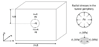
The following stress states were simulated as constant in the models: the vertical stress a1 and two horizontal stresses a2 = a3, as obtained from the geostatic conditions of the material. Vertical stress a1 was obtained as a product of multiplying the depth from the ground surface to the center of the tunnel (Ho) and the soil unit weight (y). The isotropic state (Is) considers the same magnitude for vertical and horizontal stresses (a1 = a2 = a3) and the anisotropic state (An), a coefficient of lateral earth pressure (K) (AASHTO, 2012; NCMA, 2010) equal to 0,6 was selected (Tamez-González et al., 1997). Soil radial stresses in the tunnel periphery (Pa) of 609 and 300 kPa were analyzed. These values were selected based on Equihua-Anguiano et al. (2018). Figure 1 shows the employed nomenclature. Three pressure conditions were considered from Pa = 0 kPa in order to evaluate the elastic theory, despite the fact that the deformations obtained are higher the actual ones. Pa = 609 and 300 kPa were the numerical artifices that allowed considering the presence of the lining system.
Table 1 lists the studied tunnels. Two modeling phases can be observed: in the first modeling phase, the influence of the geometry of the cross-tunnel sections was evaluated for soils with the same characteristics; in the second phase, the consequences of varying some parametric soil conditions were studied, as well as the stress state in the soil, and complemented for a third phase; and the last phase allowed elaborating the graphs proposed in this work.
In this Table, General Information indicates the descriptive nomenclature used to identify the results.
Table 1 Several studied cases and nomenclature used for the parametric study
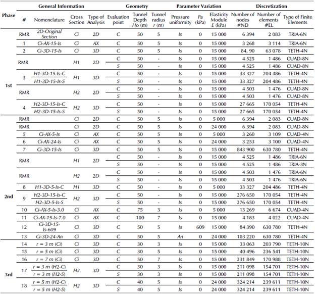
Note: 2D = Two-dimensional; AX:
Note: 2D = Two-dimensional; AX = Axisymmetric; 3D = Three-dimensional; Is = Isotropic; An = Anisotropic; Ci = Circular; C = Tunnel key; S = Tunnel floor; (-) = Not applicable; RMR = Reference models for results; CUAD-4N = Quadrilaterals-4 nodes; TRIA-6N = Triangular-6 nodes; TETH-4N = Tetrahedrons-4 nodes; TETH-10N = Tetrahedrons-10 nodes.
Source: Authors
The Geometry column mentions the two points where deformations were analyzed: the tunnel key (C) and the floor (S) (Figure 2), as well as the radii (r) of the circular sections that were modeled and the depth (Ho). In addition, the Parameter Variation column presents the stress state conditions (Is and An). The Pa shows the normal pressure applied in the tunnel periphery, as well as the elastic modulus (E) used in each simulation. Finally, the discretization details of the characteristics of the continuous medium are presented, namely the number of nodes and the number and type of finite elements.
Source: Authors
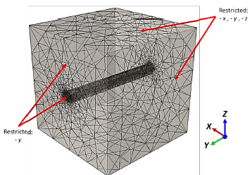
Figure 1 Stress state, geometry, convention axes (-x, -y, and -z), and nomenclature used in the 3D-RS3 numerical models
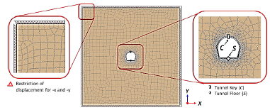
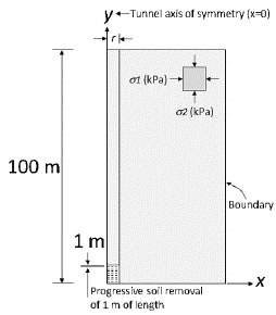
The 2D models were simulated in two stages: the in situ conditions without material removal in the tunnel section, and material removal to simulate the excavation. The excavation of the AX and 3D tunnels was simulated in stages based on in situ conditions. Afterwards, a progressive soil removal of 1 m of material length was considered, for a total of 101 excavation stages (Figure 3). The boundaries of the models were restricted as follows: the rims of the model were restricted in all directions (-x, -y, and -z), and the border of the excavation was restricted in the direction of the longitudinal axis (-y, i.e., the direction in which the excavation advanced) (Figure 4).
Source: Authors
Figure 2 Geometry, boundary conditions, convention axes (-x and -y), and nomenclature used in the 2D-RS2 numerical models
Source: Authors
Figure 3 Geometry, convention axes (-x and -y), and nomenclature used in the AX-RS2 numerical models
Source: Authors
Figure 4 Mesh 3D model, axes convention, and boundary conditions, with FEM tetrahedron elements
Tunnel sections
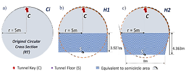
For the elastic study, three tunnel sections were analyzed, as indicated in Table 1, whose geometries are presented in Figure 5. The proposal was to form the models by matching the position of the tunnel key (C) of the different sections (Figure 6). To regard them as equivalent sections, the same transversal area was considered. The transversal area of the circular sections was obtained, and, from it, two equivalent horseshoe sections named H1 and H2 were calculated. The parametric conditions of the soil and the stress states were similar to those assigned to the original circular tunnels.
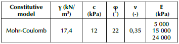
Geotechnical parameters
The soil parameters considered are shown in Table 2. The constitutive model was the Mohr-Coulomb one regarding the elastic and elastic perfectly plastic behavior. The elastic modulus (E) was varied to study the influence of different soil rigidities with three different values. The soil parameters were taken from typical material found in Morelia, Mexico, as a reference for this study.
Source: Authors
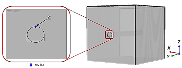
Figure 6 Coincidence of the key (C) of the tunnels with different crc sections (Ci) for r = 5 m and the horseshoe equivalent section (H1)
Elastic mesh validation
Via Equation (1) (Deere et al., 1969), the radial displacements of a circular tunnel were obtained and compared with the results obtained from the 2D and 3D models.
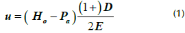
Where:
u = elastic displacement in the tunnel periphery
Y = soil unit weight
Ho = depth from the ground surface to the center of the tunnel
Pa = soil radial stress in the tunnel periphery
v= Poisson ratio
D = tunnel diameter
E = soil elastic modulus
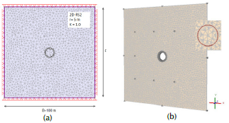
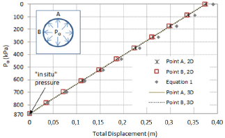
The results of the 2D models served as a reference for an approximation of the expected results in 3D. Figure 7 presents the mesh sizes for the 2D and 3D analyses. The mesh dimensions were 100 x 100m and for the 3D model, and a thickness of 1 m in the y-axis was modeled. Figure 8 shows the results obtained from the analytical Equation (1) and the numerical results of 2D-RS2 and 3D-RS3. The radial stress (Pa) in the tunnel periphery was varied, starting from the in situ stress condition (Pa = 870 kPa) until it reached zero. The analytical displacements, which are represented in Figure 8 with rhombuses, and the 2D displacements in points A and B (stars and squares, respectively) of the tunnel periphery, are very similar to each other. In the same way, the results obtained from the 3D numerical model (dashed line) are similar to the 2D results. Based on the above, the thickness of the 3D mesh was extended in length (L) in order to analyze the effect of the excavation.
Source: Authors
Figure 7 Equivalent meshes in a) 2D-RS2, 100 x 100 m, r = 5 m, 2 750 triangular elements and 1 418 nodes; and b) 3D-RS3, 100 x 100 x1 m, r = 5 m, 500 triangular elements and 10-node tetrahedron
Results
First modeling phase - elastic behavior
In this phase, the deformations were evaluated while considering an isotropic medium with the soil characteristics shown in Table 2, as well as with an elastic modulus of E = 15 000 kPa. The influence exerted by the use of different cross-sections (circular and horseshoe) was studied for 2D, AX, and 3D conditions.
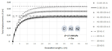
First, the analyzed tunnel section had a circular (Ci) shape with r = 5 m. To obtain the relationship between the deformations for the different geometries, the deformations (5) were evaluated in the key (C) and in the floor (S) for the horseshoe sections H1 and H2. In Figure 9, it can be seen that, for all models, the trend of the deformations describes the same behavior, and the maximum deformation is always the 2D response, as shown by 2D H1-S, 2D H1-C, and 2D H2-C show. The continuous line describes deformations for the reference tunnel (Ci 3D-15-Is). From this line, it is possible to observe the influence of the change in tunnel geometries. The measured points C and S are shown, and it can be noted that the S point exhibits the most unfavorable deformations (cross and square void symbols). Furthermore, the H1 section exhibits greater displacements. On the other hand, the C point reports virtually the same deformations as the reference tunnel. The analyzed behavior shows that the S point is the critical deformation in design, and it moves in a similar proportion depending of the geometry H1 or H2. It is concluded that the trend is similar in the key (C) of the three numerical results.
Source: Authors
Figure 9 Comparisons between the total displacements (i) and length of excavation (L) of the original tunnel (Ci, r = 5 m), E = 15 000 kPa, Pa = 0 kPa in the H1 and H2 sections
In Figure 9, the results correspond to a Pa = 0 kPa. This simulation is only valid as a theoretical reference and as a starting point for this study. In practice, its condition will never occur, given the lining system that is placed in tunnels. In this sense, the displacements observed in the floor of the H1 and H2 sections have a difference of approximately 10 cm and are greater in section H1 because the difference in the length floor is 2 m.
Second modeling phase - elastic behavior
For the second phase, the soil geometry and parametric conditions were varied in accordance with Table 1. The total displacements (5) vs. excavation length (L) graphs were obtained for the models in AX and 3D dimensions, and they were normalized as shown in Figure 10. The normalization was carried out based on the deformations (5i) taking place along of the length (L) with respect to the maximum deformation (5i max) in ten cases. The graphs describe a similar trend to those of the first modeling phase, and the separation observed between the lines only shows the influence of r on the deformations; a greater r causes greater displacements in shallower excavation lengths, as seen with the filled square symbols. It can also be noted that there is an interval for the r = 5m (Ci), as well as in its corresponding equivalent horseshoe sections (H1 and H2), where the trend shows a very good match. In Figure 10, it can be seen that the normal pressure of Pa = 609 kPa, described with triangles (Ci-3D-15-Is-609), agrees with the results of the models with Pa = 0 kPa (e.g., Ci-3D-15-Is void circles and H1-3D-5-Is-C dashed symbols).
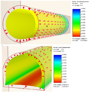
In the same way, the anisotropic and isotropic conditions were compared, as well as the variation of the E and the simulated conditions (3D and AX). This means that, by modifying Pa, the cross-section, E, K, analysis type, and the two evaluated points (C and S), the trend of deformations is not affected when normalizing the lines while considering the same radius (r = 5m). The lines with a similar behavior are Ci-3D-15-Is, Ci-AX-24-Is, H2-3D-15-Is-C, H2-3D-15-Is-S, Ci-3D-24-An, H1-3D-5-Is-C, and Ci-3D-15-Is-609. Figure 11 shows the 3D kinematics of the deformation, obtained for the conditions of Ci-Is in a circular tunnel and an H1 tunnel section. In the same Figure, the displacements tend to zero, as observed via the blue area. This happens when the simulated excavation length is next to the end of the progressive soil removal of 1 m in length of the material (L = 18 m in Figure 11). Nevertheless, when the excavated length is the total simulated one, the displacements in the tunnel periphery correspond to the same deformations in the entire tunnel periphery.
Source: Authors
Figure 10 Normalized graph of deformations (5i) along of the length of excavation (L) with respect to the maximum deformation (5i max) for different tunnels and parametric conditions
Displacement graphs and polynomial expressions -elastic behavior
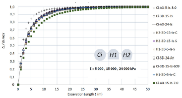
The displacement graphs were elaborated based on Figure 12. The trend lines Ci-AX-24-Is, Ci-3D-15-Is, Ci-3D-15-Is-609, Ci-3D-24-An, H1-3D-5-Is-C, and H2-3D-15-Is-C represent the FEM results obtained for r = 5m in the key (C) of the tunnel, in which the displacements 5 were normalized with respect to y, Ho, Pa, E, and the maximum elasticity modulus considered for rigid soil (Emax = 24 000 kPa). The lines are very close to each other; thus, it is possible to consider the same behavior. On the other hand, the separation observed in the H1-3D-Is-5-C and H2-3D-Is-5-S lines is attributed to the automatic building of the mesh refinement. As a result, it is determined that parameters such as E, Pa, Is, An, and the shape H1 and H2 do not have a great influence on the normalized displacements of the C point for all tunnel sections. Greater displacements take place at the S point in the H1 and H2 sections with respect to the C point, and they can be obtained from this graph. From these results, it is concluded that this normalization works for every numerical simulation performed in FEM (3D and AX).
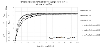
Another normalization was performed for the three radii studied, adding rmax/r multiplication (rmax = 7 m) to the normalization shown in Figure 13. Note that the three radii have the same maximum normalized value, and only the first meters of the excavation length have different displacements, with greater displacements for longer radii (r=7m). In this way, the results show the possibility to obtain the displacements by using any radius between 3 and 7 m (Figure 14).
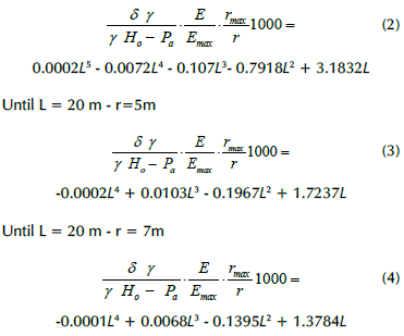
Based on the above-presented analyses, the polynomial expressions (2), (3), and (4) were calculated by polynomial interpolation (Teodorescu et al., 2013; Stoer and Bulirsch, 1993; Hamming, 1987; Conte and de Boor, 1972) using the Mathematica software (Wolfram Research, 2020), which provides a simple and good way to estimate the analytical expression -which is essentially a function- over the range of the measured points. These polynomial expressions are presented to obtain the displacements 5 in the tunnel periphery for r = 3, 5, and 7 m, respectively. Figures 14apresents the adjustment.
Where:
δ = total displacement in the tunnel periphery
γ = soil unit weight
Ho = depth from the ground surface to the center of the tunnel
Pa = radial stresses in the tunnel periphery
E = Elastic modulus of the soil
Emax = maximum elasticity modulus (24,000 kPa)
r = radius of the tunnel
rmax = maximum radius used (7m)
L = length of the excavation
Source: Authors
Figure 12 Excavation length (L) vs. normalized elastic displacements for r = 5 m, Ci, H1, H2, E = 5 000, 15 000, and 24 000 kPa under isotropic Is and anisotropic An conditions, considering models in AX and 3D and for different Pa
Source: Authors
Figure 13 Excavation length (L) vs. normalized elastic displacements for r = 3, 5, and 7 m for the circular section Ci
Deformation factors (Fi)
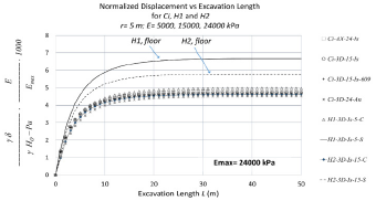
Figures 14a, 14b, and 14c present the average of the lines of the deformations б for all reported simulations. Note that the trends are the same for all simulations, with similar values for all lines. From the maximum displacement obtained from the AX-FEM simulations, a relationship was proposed by comparing these results against the displacements (6imax) obtained from the two horseshoe sections.
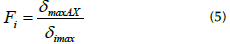
Where:
Fi = deformation factor
δmaxAX = maximum deformation in AX FEM model δimax = maximum deformation in FEM models for H1 and H2
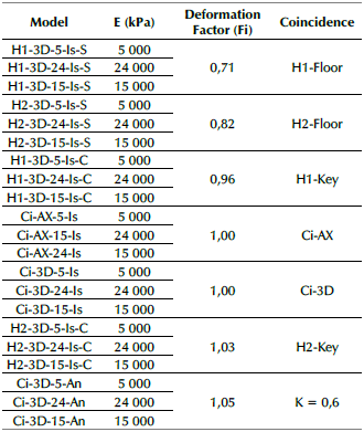
This relationship allows obtaining the maximum displacements in the key (C) and in the floor (S) of a horseshoe section (H1 or H2) from axisymmetric (AX) simulations while using the equivalent criterion is proposed in this article. The deformation factors (Fi) obtained are presented in Table 3.
Elasto-plastic behavior
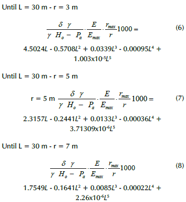
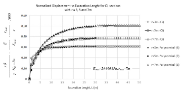
In this section, the steps followed for the elastic study were emulated, and the normalization curves were obtained in the same way. The numerical models were replicated according to Table 1, and, in order to obtain a perfectly elasto-plastic behavior, the shear parameters c and ф were duplicated according to RS3. In this case, a Pa = 300 kPa was modeled. Even though this pressure is low, this value allows soil to go from its elastic interval to its plastic interval. Figure 15 presents the normalized curves for the three radii studied, considering only circular sections, as well as the adjustment obtained from the proposed polynomial expressions (6), (7), and (8). For the case of the r = 3m (Ci), a leap is observed in the first meters of the excavation length, which is due to the fact that, for this radius, the Pa is high, so it decreases the displacements in the first meters, although there is an L where de maximal displacement is reached.
The polynomial expressions proposed to obtain elasto-plastic displacements 5 in the tunnel periphery for r = 3, 5, and 7 m respectively are as follows:
Comparisons with other works
Comparisons with the results reported by other authors were conducted by applying the expressions proposed in this work and the displacements and data informed in the following papers: Arnau and Molins (2012) studied the 3D structural response of segmental tunnel linings, and their results constitute the obtained displacements in isolated rings and joints; Katebi et al. (2015) studied the influence of ground stratification and tunnel and surface building specifications on shield tunnel lining loads using FEM; Miro et al. (2014) presented the study of a global sensitivity analysis for subsoil parameter estimation in mechanized tunneling; Xing-Tao et al. (2019) presented a three-dimensional stress transfer mechanism and soil arching evolution as induced by shield tunneling in sandy ground.
Source: Authors
Figure 15 Excavation length (L) vs. normalized elasto-plastic displacements for r = 3, 5, and 7 m, circular section Ci
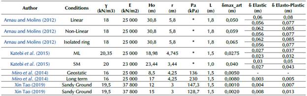
Table 4 shows a summary of the parameters collected from the papers, with the purpose of comparing them with the results obtained using the expressions (2), (3), (4), (6), (7), and (8). The displacements selected from the papers are labeled with δmax_art, and those obtained with the polynomial expressions are labeled with δ Elastic and δ Elasto-Plastic for the elastic and elasto-plastic displacements, respectively. The parameters substituted in equations correspond to those found in the papers. The L considered is the excavation length corresponding to one day or to the ring thickness placed in the tunnels.
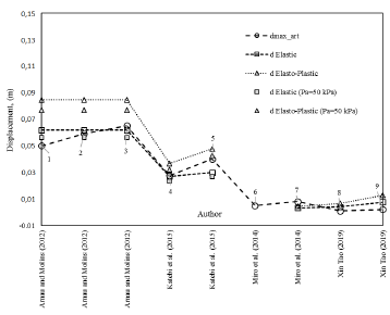
Figure 16 shows the displacements calculated with the polynomial expressions vs. the displacements reported by other authors. For the five first cases, the Pa was not reported. For said cases, two values (Pa = 0 and 50 kPa) were considered, and the displacements obtained are presented in Table 4 and Figure 16. The results for the three cases mentioned by Arnau and Molins (2012) -which consider a Pa = 0 kPa- are lower than those reported in this paper. As expected, if Pa = 50 kPa, the displacements decrease and are closer to the displacements found by Arnau and Molins (2012). In general, it can be noted that all of the calculated displacements follow the same trend and are very close to those found by other authors. In the case where the Pa applied is greater than the geostatic conditions, the polynomial expressions are not applicable, as in case 6 (Miro et al., 2014)
For cases 6, 7, and 9, the displacements obtained with the proposed equations and those of other papers are very similar. In all cases, the elasto-plastic response is greater that the elastic displacements obtained, so this is a conservative way to evaluate displacements before the design phase.
Source: Authors
Figure 16 Comparisons between the displacements obtained from the polynomial expressions proposed in this work and those reported by other authors
Conclusions
This study presents polynomial expressions and graphs to obtain 3D deformations in the periphery of different tunnel sections. These were obtained from the numerical simulations of a parametric study carried out in RS2 and RS3. This approach reduces the time required to obtain said deformations and evaluate them for different excavation lengths in the face of unexpected geotechnical changes encountered during drilling, as well as when a rapid evaluation of deformations is required.
The polynomial expressions were obtained from numerical 3D results and through an interpolation with the Mathematica software. As a complement of the polynomial equations, deformation factors (Fi) were obtained, which can be applied to predict deformations in the key or floor of two horseshoe tunnel sections. Fi relationships depend on the maximum displacements obtained from an axisymmetric simulation (AX).
In the numerical simulations, different displacements were observed in the first meters of the 3D excavation, and there was a distance at which the maximum displacement takes place depending on the tunnel characteristics. Thus, the application of the graphs supersedes the use of a 3D-FEM analysis, and it is possible to evaluate 3D displacements for different excavation lengths until the displacement reaches its maximum value.
Despite the fact that elastic theory is a classical and a relatively simple design method, it provides reliable designs for the case of tunnels that are based primarily on displacements in the tunnel periphery. 2D analysis provides the maximum displacement in a tunnel. If this value is used in design, it can cause an overdesign of the infrastructure, i.e., if it is considered for an excavation length greater than L = 13 m for r = 3 m and L = 20m for r = 5 and 7 m.
In the same way, a first elasto-plastic approximation is presented, along with polynomial equations considering a low internal pressure, aiming to ensure that the soil is in its elasto-plastic interval.
The influence of the variation in parametric conditions and the stress state of the tunnels were studied. It was observed that soil rigidities do not have an influence on the normalized results, unlike radii, as larger displacements are caused in smaller excavation lengths for larger tunnel diameters of the tunnels. Shorter diameters result in lower displacements. In this regard, the displacement is not proportional to the radius.
At higher normal pressures, there are lower deformations. Nevertheless, when this is normalized, there is no influence on the displacements. The polynomial expressions or graphs presented herein can be used to obtain displacements for different Pa values, determined as a function of the value taken for the tunnel lining while considering the length of the tunnel excavation.
For the case of the anisotropic conditions, it can be stated that the average is very similar. Graphs including the results obtained from the representative models of the parametric variations normalized with the maximum deformation were presented in order to understand the impact of modifying them. It was observed that the same deformation tendency was maintained.
The displacements obtained by other authors are very close to those of this study (elastic and elastoplastic). However, the elasto-plastic response is higher that the elastic one, which makes this a conservative way to evaluate displacements before the design phase.
Finally, this is the beginning of other considerations that need to be made, such as the determination of the displacements along the construction length and the possibility of a three-dimensional understanding of the effect on the internal pressure, with the aim to determine the time to place the lining or to improve tunnel design. It is necessary to carry out more studies that allow understanding displacements under plastic conditions in order to provide better estimations according to the real soil behavior.

