


 Inglés (pdf)
 Articulo en XML
 Referencias del artículo
 Enviar articulo por email
 Citado por SciELO
  Citado por Google
  Similares en
SciELO
Similares en
SciELO  Similares en Google
 Permalink
Introduction
Developing technologies, increasing population, and growing industrialization have increased energy consumption and the amount of required energy (Ayaz et al., 2020). In addition, due to the gradual decrease in the use of fossil fuels and the damage they do to the environment, environmentally friendly practices have taken an important place in our lives. CO2 emissions are regarded as the source of the most serious damages caused by fossil fuels to the environment. According to the reference values of 1990 under the Kyoto Protocol, the European Union (EU) aims to reduce its greenhouse gases (GHG) emissions by 80-95% as of 2050. Similarly, road, rail, sea, and air transport should contribute to this aim by reducing the 1990 emission levels by 60% as of 2050 (de Gennaro et al., 2019). In this context, electric vehicles (EV) are an effective solution to reduce CO2 emissions (Cai and Zhao, 2021).
EVs, which constitute the best alternative for an environmentally friendly transportation vehicle, are also an ideal solution to the problems experienced regarding urban air quality (Hooftman et al., 2016). Especially in recent years, the production and development of electric or hybrid vehicles has been increasing due to energy and environmental issues (Jang et al., 2015). By using electric vehicles (EVs) or hybrid electric vehicles (HEVs) instead of conventional fuel vehicles, substantial reductions in carbon emissions will occur, and improvements in urban air quality will be achieved. This is also very important for reducing cases of respiratory diseases (de Gennaro et al., 2019).
Today, EVs, which have significant positive effects on the quality of life, consist of various parts, namely the electric machine, the battery group, the on-board charger, and the electric power control unit. Research and development (R&D) studies continue for all these parts in parallel with developing technologies. EV-related technologies such as electric motor drive design and selection, power converter topologies and control algorithms, and power supply and system configuration are under extensive development (Cai and Zhao, 2021). One of the common target points of these studies is minimal energy consumption. Within this framework, electrical machines are of great importance for EVs. There are many different studies in the literature in the field of electrical machines for EVs.
Electrical machines are also widely used in industrial applications (Jang et al., 2015). The use of copper (Cu) in windings, which are an important part of electrical machines, is common since this element is a good conductor (Ayaz et al., 2020). Cu is widely used, especially in the windings of high-performance electrical machines. This is due to a high electrical conductivity, enabling high current density machine designs that minimize DC winding losses (Widmer et al., 2016). In addition, the high strength and increased electrical conductivity of Cu alloys are highly desirable for many wire and cable applications (Islamgaliev et al., 2014).
Sullivan, in his study in 2007, stated that the prices of Cu would be both high and variable in the future, and, therefore, products with a large amount of Cu, such as power electronics and transformers, should be reassessed in terms of cost. He also indicated that it is not a preferred method to reduce the efficiency of the machine in order to increase the amount of Cu, and Cu windings can be completely removed by using Al windings (Sullivan, 2007). In this context, in recent years, Al materials have been used as an alternative for copper windings in transformers and electrical machines.
The most important reason for this is that Al materials have good conductivity and are abundant and cheap around the world (Hergul et al., 2020). In addition, the cost of an Al conductor of the same resistance and length is significantly lower than the cost of a Cu conductor. Al has a cost approximately 30% of copper per unit mass, or 10% per unit volume (Sullivan, 2007; Widmer et al., 2014, 2016). Furthermore, recycling is very important nowadays: while Al can be recycled with steel, Cu is a major pollutant in the steel recycling process (Widmer et al., 2014, 2016). This is one of the disadvantages of using Cu.
The weight of electrical machines is of great importance according to their use areas. A low mass is particularly important in the design of 'mobile' electric motors used in applications ranging from electric vehicles to electric aircraft (Widmer et al., 2014). At this point, Al is one step ahead of copper. Al has a mass density of 30% that of Cu. Therefore, it is an attractive conductor in applications where low mass is important (Widmer et al., 2014, 2016). The most important feature to be considered at this point is that the cross-sectional area of an Al conductor is 56% larger than that of Cu for the same current carrying capacity (Pryor et al., 2008). Therefore, the material cross-section conditions must be taken into account when selecting the material.
In this study, the winding structure of a SRM, which is one of the electrical machines that is preferred for EVs and will have an even more important place in the future, as it does not contain rare-earth magnets in its structure, was defined as Al and Cu, and transient analyses were carried out. As a result of the analysis, the performance of the machine and the weight of the winding were compared.
Switched reluctance machines (SRMs)
Conventional SRMs have one of the simplest structural configurations among electrical machines (Gupta et al., 2021). SRMs that do not have windings or magnets in the rotor have only stator windings. Rotor rotation and energy conversion take place according to the principle of minimum reluctance (Sahin et al., 2012; Sun et al., 2021). In other words, SRMs convert electrical energy into mechanical energy with reluctance force (Omaç et al., 2018).
SRMs are strong candidates for EV and HEV applications due to their simple structure, low cost, flexible control, strong environmental sustainability, high fault tolerance capability, and high starting torque (Cai and Zhao, 2021; Haque et al., 2021; Li et al., 2015; Wang and Li, 2020). In particular, their high fault tolerance capability enables SRMs to work reliably and efficiently in harsh environments, such as automotive and aviation applications (Haque et al., 2021). Compared to permanent magnet (PM) machines, SRMs are in a more advantageous position to be used in EVs due to these features (Li et al., 2015). PM machines are widely used for wind energy generation due to their high efficiency and high power density (Jiang et al., 2021).
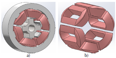
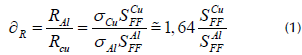
Additionally, since SRMs use iron cores in magnetically fully saturated regions, they have a much higher power density when compared to other machines such as induction motors and brushless DC machines. Therefore, the machine size is much smaller than that of other machines (Yoon, 2020). This feature constitutes an advantage for the aviation and automotive sectors. In addition to all these advantages regarding SRMs, these electric machines have the ability to work for a long time under high temperature and high speed conditions (Gan et al., 2021). Figure 1a presents the sample model of a 6/4-pole SRM, and Figure 1b shows the machine phase windings.
High-speed SRMs that face increasing power density requirements in diverse applications such as EV and HEV have a limited area to improve torque and power. The performance improvement of high speed SRMs is basically divided into two stages: the first is to increase the motor torque and the other is to improve the loss distribution. The most direct method of increasing the torque is to improve the winding structure and current density, given that, in high speed SRMs, only stator windings are energized. Therefore, windings are very important in SRMs.
Nowadays, flat copper wire, hairpin windings, and similar improved winding structures are used in various machine types (Chai et al., 2020). According to the winding structure to be applied to the machine, the selection of the material to be used is also important, as it directly affects machine losses. In addition, one of the important points to be considered in loss distributions is the control parameters of the machine. Control parameters directly affect the iron and Cu (winding) losses of the machine and therefore affect its efficiency (Yan et al., 2020).
Materials and method
The design of electrical machines is particularly challenging for electric or hybrid vehicle applications. In the design process, an optimization based on the evaluation of the different losses that occur in the machine is required for each operating point (Boumesbah et al., 2021). A highperformance SRM design, on the other hand, is usually handled in a two-step process. In the first stage, preliminary design analyses are carried out. At this stage, various options, such as stator/rotor pole combinations, inner and outer rotor topologies, winding configurations, and different materials, among others, are examined via finite element analysis (FEA). Thus, the proposed design options are compared to obtain a start-up design. In the second and final stage, optimization techniques such as a heuristic approach or a genetic algorithm are used (Rocca et al., 2020). This study involves the first stage of machine design. The winding configurations of the proposed SRM model were evaluated (Cu and Al) at equivalent resistance values, and FEA analyses were performed. The results obtained were compared, and a start-up model was proposed for the phase winding material. Coils for electrical machines are traditionally handmade components and are a limiting factor for machine operation. Studies on issues such as the fabrication and modulation of the coils are also an important step in production (Silbernagel et al., 2019).
Comparison of Al and Cu winding materials
One of the important components of an electrical machine is its windings, which consist of coils. Coils consist of wires made of conductive material surrounded by resistive insulating material. A conductive core is desired to have a low electrical resistance and minimize the Joule losses. These materials are generally copper, silver, gold, and aluminum. Table 1 presents the electrical resistance and density of metals and alloys commonly used in electricity at room temperature (Silbernagel et al., 2018).
Table 1 Metals and alloys commonly used in electrical applications
| Main element | Electrical resistivity (μΩ-cm) | Density (g/cm3) |
|---|---|---|
| Pure copper (Cu) | 1,7241 | 8,94 |
| Pure aluminum (Al) | 2,6548 | 2,688 |
| Aluminum 1350 (1350 Al, electrical alloy) | 2,82 | 2,705 |
| Pure silver (Ag) | 1,586 | 10,492 |
| Pure gold (Au) | 2,192 | 19,37 |
Source: Silbernagel et al. (2018)
Among the elements and alloys given in Table 1, Cu and Al are the two most commonly used materials for conductors and bus bars in electrical equipment. The Cu used in electrical equipment has a pure 98% conductivity, according to the International Annealed Copper Standard (IACS) (Pryor et al., 2008). Pure Al, on the other hand, has good conductivity, but it is too soft to be processed for the manufacture of electrical wires (Pryor et al., 2008; Silbernagel et al., 2018). For this reason, 1350 Aluminum (1350 Al) alloy was developed for electrical purposes. The 1350 Al alloy is categorized as EC (Electrical Conductor) class aluminum, with 99,50% Al content. Although 1350 Al was developed for electrical purposes and has 61,2% the conductivity of Cu, it is still soft when compared to Cu in terms of mechanical properties (Pryor et al., 2008; Silbernagel et al., 2018).
In addition, in recent years, both automotive and electrotechnical applications require innovative materials that can be used to replace expensive and heavy Cu conductors. Therefore, there are transitions to complex, gradient, multiphase, and composite materials with tailored microstructures and properties for specific functionalities (Kunčická et al., 2022).
Metallic clad composites (MCCs), which typically consist of two or more separate components with different physical or chemical properties, show superior behavior and properties than the components used, given the combination of the components used. In the literature, there are various MCCs (e.g., Al/Mg, Al/Ni, Al/Sn, Cu/Ni, CuAi, Cu/Zr, Al/Cu/Mg, Al/Cu/Sn, Al/Cu/Zn, Al/Cu/steel, AlAi/Mg, AlAi/Al, Cu/Al/ Cu, etc.). However, the Al/Cu system is among the most popular, as it is very promising for both automotive and electrotechnical applications (Kunčická et al., 2022).
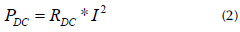
Since the electrical conductivity of Al windings is lower compared to those of Cu, the resistance value per unit winding length is higher, as shown in Equation (1) (Widmer et al., 2014, 2016).
where R is the resistance, σ is the electrical conductivity of the winding material, and S FF is the slot fill factor. The electrical conductivities of Al and Cu at 20 °C are σ Cu = 58,0x10⁶S/m and σ AI = 35,4x10⁶S/m (Widmer et al., 2014, 2016).
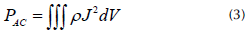
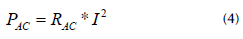
Cu losses in a fixed area are calculated using the Ohmic DC (direct current) resistance (R DC ) and current (I), as given in Equation (2) (Schenk and de Doncker, 2013).
In general, the total losses are calculated with the specific resistance ( P) and the current density (ρ) as given in Equation (3) (Schenk and de Doncker, 2013).
Additionally, Equation (3) can be rewritten as given in Equation (4) with an equivalent AC (alternating current) resistor ( R AC ) according to Equation (2) (Schenk and de Doncker, 2013).
As seen in Table 1, the electrical resistances and densities of Cu and Al are different. In order for their resistances to be equal, the expression in Equation (5) must be fulfilled.
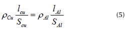
In Equation (5), ρ is the specific resistance (Ωm), l is the winding length (m), and S is the winding cross-section ( m 2).
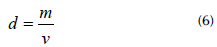
When the lengths, cross-section diameter, and specific weights of the conductors used in both winding models are substituted into Equation (6), the weight of the winding used for a 3pole is found. In Equation (6), d is the density ( kg / dm ), m is the weight ( kg ), and v is the volume ( dm 3 ).
In addition to all these, when compared to Au and Ag, Cu is widely used in electrical components, given its low electrical resistance and average price balance (Silbernagel et al., 2019). However, Al is less costly than cu. Thus, it can carry more current per kilogram or dollar. With this feature, it provides great advantages in automotive and aviation applications, among others where weight and cost are important (Silbernagel et al., 2018). When the prices per kg of Al and Cu are compared, it is observed that, while aluminum was $2,35/kg in 2021, Cu was $9,04/kg (London Metal Exchange, n.d.).
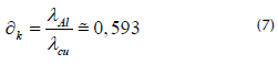
The thermal conductivities of Al and Cu are 381,1WmT 1 K 1 and 230Wm-1K-1, respectively. The ratio for their thermal conductivities is given in Equation (7) (Widmer et al., 2016).
They Al and Cu both oxide when exposed to the atmosphere. Al oxidizes easily when exposed to air, and a strongly bonded, hard outer layer of electrically insulating oxide quickly forms around the metal. Cu also oxidizes when exposed to air, but the oxide formed is relatively soft and conductive, although not as conductive as the base metal (R. F. Frank and Morton, 2005, 2007).
Aluminum and copper windings for SRMs
A SRM is a rotating electrical machine with nonlinear materials (Boumesbah et al., 2021). It also has a nonlinear electromagnetic structure that is highly dependent on changes in phase current and rotor positions (Alharkan et al., 2021). Because of these features, when creating a SRM model, it must include the non-linear behavior of the machine and the rotation features, as this affects its behavior. Within this context, the use of the Finite Element Method (FEM) provides a high precision (Boumesbah et al., 2021). In addition, when the results obtained from numerical methods are compared to those from analytical methods, they can be seen to have a higher accuracy. Therefore, numerical methods are preferred by users, among which finite element analysis is one of the most widely used (Alipour-Sarabi et al., 2020). Due to all these advantages, the proposed SRM model was analyzed using 2D modeling. To this effect, the Cu winding was first assigned, and then the Al winding. Afterwards, transient analyses were carried out using the FEA. The general parameters and geometric dimensions of the proposed SRM model are given in Table 2.
Table 2 General parameters and geometric dimensions of the proposed SRM
| General dimensions | General dimensions | General electrical | |||
|---|---|---|---|---|---|
| of stator | of rotor | parameters | |||
| Outer diameter | 100 mm | Outer diameter | 40 mm | Rated speed | 1 750 rpm |
| Inner diameter | 41 mm | Inner diameter | 14 mm | Rated voltage | 50 V |
| Number of the poles | 6 | Number of the poles | 4 | Rated output power | 1 000 W |
| Yoke thickness | 10,6 mm | Yoke thickness | 5 mm | Operating temperature | 75 cel |
Source: Authors
Finite element analysis
Finite element analysis (FEA) is a computer simulation technique used for analysis in engineering. In this technique, a numerical strategy called the Finite Element Method (FEM) is used (Kumar and Isha, 2008). By using the FEM, approximate solutions of partial differential equations (PDE) such as electrical, magnetic, or temperature distribution equations are found (Son-In and Amornsawatwattana, 2022). FEA is generally divided into three stages. The first one is pre-processing, in which the FEM and the environmental factors to be applied to it are defined. The second is the analysis solver stage, where the solution of the finite element model is carried out, and the last stage is the post-processing of results, where visualization tools are used (Kumar and Isha, 2008).
FEM analysis is essential because of the double salient structure of SRMs and the intense saturation effects that occur at partially aligned stator-rotor poles (Kumar and Isha, 2008). In this study, 2D FEM analysis was performed via the Ansys/Maxwell software. For the analysis, the modeling and assignment of material properties, the determination of boundaries, the definition of excitations, the creation of the mesh structure, and the assignment of setup properties are first performed. At this point, one of the important issues to be considered is the mesh structure. The quality of the FEM analysis results depends on the density within the global mesh structure. In high-precision studies, a denser mesh structure can be used at the points where high reliability is desired (ManâaBarhoumi et al., 2015). In the analysis of this study, the Backward Euler method was selected among the time integration methods. The basic governing equations used for simulation were Maxwell's equations. In FEA, profiles such as torque, magnetizing, self-inductance, and mutual inductance, required in the analysis and modeling of SRMs, are obtained depending on the change of phase current and rotor position via Maxwell's equations. They can be calculated from the flux density B (Tesla or Wb/ m2) and the field intensity H (Nguyen and Ta, 2011).
The differential form of Maxwell's equations, which can be written in differential and integral forms, is given in Equations (8)-(11), as Faraday's law of induction, Gauss's law for magnetism, Ampere's law, and Gauss's law for electricity, respectively (Ansoft, n.d.).
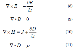
In Equations (8)-(11), E is the electric field intensity (V/m), B is the magnetic flux density (Tesla or Wb/m2), H is the magnetic field strength (A/m), D is electric flux density (C/ m2), t is time (s), ρ represents the electrical charge density (C/m3), and J represents the current density (A/m2).
For SRMs, the magnetic potential vector equations in each direction are used to calculate electromagnetic issues, as shown in Equation (12) (Son-In and Amornsawatwattana, 2022; Torkaman and Afjei, 2009).
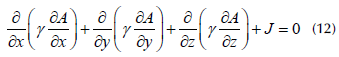
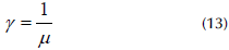
where A represents the magnetic vector potential (Wb/m) and γ represents magnetic reluctivity. The relationship between magnetic reluctivity γ and magnetic permeabilitiy μ (H/m) is expressed in Equation (13). In addition, m = μ 0 xμ r (Son-In and Amornsawatwattana, 2022).
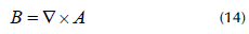
Considering appropriate boundary conditions, Equation (12) is solved to obtain the magnetic vector potential A . Moreover, the magnetic flux density B can be expressed in terms of A, as given in Equation (14) (Torkaman and Afjei, 2009).
The relationship between the magnetic field strength H and the magnetic flux density B can be expressed as shown in Equation (15) (Kim and Doh, 2016).
Results and discussion
All other analysis conditions were kept the same, except for the winding material type of both models, whose transient analysis was performed using FEA. Here, the effects of many factors such as air gap width, pole head, and yoke properties on motor output performance can be examined. However, since the main point of the study was the effect of the winding material on the output performance, all other geometric and material properties were kept the same. The induced voltage, torque, flux, and loss graphs obtained from the analyses are given in Figures 2-5.
Figure 2 presents the induced voltage graphics of the Cu- and Al-wound SRM model, Figure 3 presents the torque curves of the two models, Figure 4 shows their magnetic flux lines, and Figure 5 presents their loss curves.
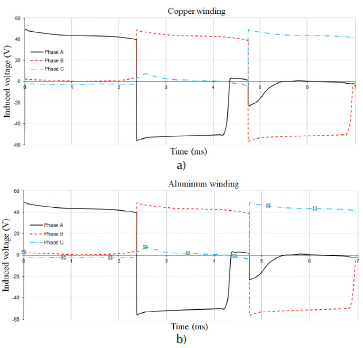
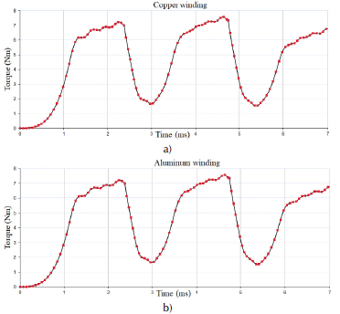
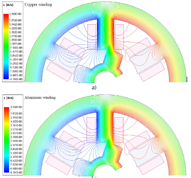
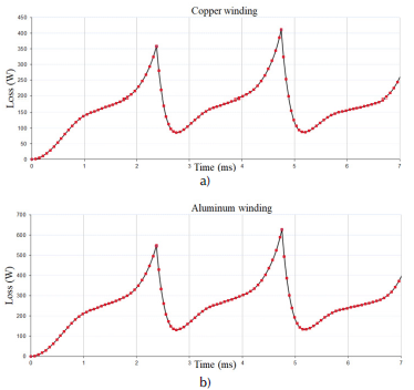
As can be seen in Figures 2-4, both models were induced with the same voltage, and similar flux distributions and similar torque plots were obtained. However, the important point to be considered here is the losses in the windings. As it can be seen in Table 1, since the electrical resistivity values of Cu and Al used in the windings are different, the losses in the windings are accordingly different. The loss curves of both models are shown in Figure 5. The losses in both models are similar in characteristics but different due to the winding resistance. When the average losses in the Cu and Al winding models were calculated by taking the average of the graphs given in Figure 5, they were obtained as P ioss-cpo = 167,2W and P ioss-alu = 255,1W. In order to calculate the output power of both models, the power-torque relationship given in Equation (16) was used.
where P is the motor power, T is the torque, ω r is the angular velocity, and n r is the rotor rotation speed in rpm. In both models, n r = 2100 rpm was analyzed. The average output torque of both models was obtained as 4,6 Nm by taking the average of the graph given in Figure 3. By writing the average torque and rotational speed into Equation (16), the average output power of both models was obtained (1 011,08 Watts). However, since the losses are different in both models, the input power is also different. Therefore, their efficiency is accordingly different. The efficiency of both models can be calculated via the expression given in Equation (17).
where ƞ represents the efficiency, P out represents the output power, and Pn represents the input power (P out + P loss ). When Cu winding was used in both models with the same output power, P jn = 1 178,28 W was obtained, and it was obtained as P = 1 266,71W when Al winding was used. Therefore, the efficiency was obtained as ƞ cop 85,81% for the Cu winding model, and as ц а1и = 79,86% for the Al winding model. However, the important point to be noted here is that the improvement or protection of the motor performance is essential in the studies carried out in electric motors. In addition, both models must have the same efficiency, and therefore the same losses, in order for them to be compared. The absolute condition for this is that the winding losses in both structures must be the same. In other words, the winding resistance of both proposed models should be the same.
As seen in Equations (2)-(4), the main element in the losses occurring in the machine windings is the winding resistance. Therefore, in order for the windings made of different materials (such as Cu and Al) not to have a negative or different effect on the machine output performance, the resistance values must be equal.
When Cu winding was used for the proposed SRM model in this study, Cu wire with a length of approximately 26 m and a wire diameter of 0,5 mm was used for one pole. In this case, the resistance of one pole copper winding was calculated as 2,36 O. In this case, the pole winding resistance of the second proposed model with Al winding should be 2,36 O. To this effect, considering the motor depth and the winding filling factor, the length of the Al conductor was kept constant, and the cross-sectional area was increased. When the necessary expressions in Equation (5) are replaced, the diameter of the Al conductor wire to be used is approximately 0,63 mm.
By replacing the necessary expressions in Equation (6), it can be stated that 45,87 g of Cu should be used for a pole in the Cu-wound SRM, while 21,96 g of Al should be used for a pole in the Al-wound SRM. In this case, a 43,40% reduction in winding weight occurs, with the same performance. Although there are changes in the geometrical properties of the SRM, such as diameter and depth, among others, when the Al winding is used, there is a significant decrease in the weight of the winding. Therefore, the Al-wound machine will be lighter than the Cu-wound one. This will provide a significant advantage in mobile robots used in EVs, and especially in the aviation industry.
Conclusions
In this study, copper and aluminum materials were compared in terms of the winding structure of SRMs, which are widely used in electric land and air vehicles. One of the most important parameters of electrical machines is their windings. In recent years, fluctuations in Cu prices have adversely affected electrical machinery manufacturers, as well as end users. Therefore, Al has been widely used due to its features and price-benefit balance. In this study, the winding structures of the proposed SRM model were examined with both Cu and Al, and transient analyses were carried out. It was seen that the obtained torque and flux results were quite close. In order for the results obtained in the comparison to be realized in practice, the losses in the winding, and thus the winding resistances, must be equal. Considering the winding filling factor, the sections were changed while keeping the same winding length. Winding weights were calculated after obtaining the winding cross-section and length with equal resistance. When Cu winding is used, 45,87 g of copper should be used for one pole, while, in the case of Al, the pole winding weight should be 21,96 g. As a result, it has been calculated that Al implies 43,40% lighter windings with equal resistance. Thus, it is concluded that aluminum is a conductor that could be easily preferred as a winding material in applications where the total mass of the machine is important.
As a continuation of this study, the thermal behavior of the Al and Cu winding structures of the SRM applied in this study could be examined. In addition, the aging of the windings could be evaluated by observing the effects of the phase currents on the winding when the power switches used in the driver circuit operate at different frequencies (such as 5, 10, and 15 Khz).

