


 Inglés (pdf)
 Articulo en XML
 Referencias del artículo
 Enviar articulo por email
 Citado por SciELO
  Citado por Google
  Similares en
SciELO
Similares en
SciELO  Similares en Google
 Permalink
Introduction
Non-conventional renewable energy sources (NCRES) are necessary for modern electricity systems, both in the National Interconnected System (NIS) and in non-interconnected zones (NIZ). This type of energy is indispensable for sustainable economic development, the reduction of greenhouse gases (GHG), and the energy security of the system. The latter has great relevance in countries of the Pacific and Caribbean Region, as the El Nino phenomenon and the effects of climate change tend to be increasingly relevant elements for the planning and operation of electrical power systems. Likewise, renewable energies contribute directly to Goal 7 of the Sustainable Development Goals (SDGs), which is related to Affordable and Clean Energy (Swain and Karimu, 2020).
Several reviews on AC and DC microgrid operation, applications, modeling, and control strategies have been presented in the literature Shahgholian (2021); Dragičević and Li (2018); Quintero-Molina et al. (2020); Gao et al. (2019). An advantage of using these networks is that they provide more reliability to the system, since they allow power generation to take place closer to the load centers. In addition, this increases the quality of the energy supplied. Likewise, microgrids can operate in two modes: island and normal (connected to the network). Considering the vulnerability of electrical power systems, the island mode provides safety Lunaef al. (2020).
DC microgrids have additional benefits, and they include reduced stages in the AC-DC interfaces required for residential loads. Both AC and DC microgrids operate autonomously, controlling parameters within the established limits. However, DC microgrids have a complex control architecture, mainly due to instantaneous power balance. The most important factors in their design are the generation-load power balance and the battery's state of charge (SOC) Hernandez et al. (2021).
NCRES such as wind and solar photovoltaic (PV) generation could serve as a backup during El Nino events. There is a complementarity between hydroelectric resources and NCRES during drought periods. However, the massive implementation of NCRES constitutes drawbacks for operating electrical power systems according to their power and distribution levels, given the randomness of these primary resources. For a massive expansion of these distributed energy resources (DERs), it is essential to develop novel control functionalities that mitigate the large-scale impacts of these technologies Luna et al. (2020). In Hernandez et al. (2021), an islanded microgrid for a rural area was designed and simulated in PSCAD/EMTDC. This design considered a battery to store energy when solar irradiance is low. In this research work, the SOC of the battery design uses the incremental conductance algorithm.
Rajanna (2022) designed a system consisting of a PV system with maximum power point tracking (MPPT), a battery storage system, and an improved three-level neutral point clamped (NPC) inverter. The NPC inverter accurately generates the required AC voltage via a modulation method for a three-level vector, particularly in the face of unbalanced DC voltages. This work evaluated the performance of the NPC inverter in different configurations, considering the SOC characteristics under varying solar irradiance levels.
Srikanth Goud and Sekhar (2023) presented a PV system connected to a DC-DC converter, which was then connected to a DC-link bus and converted to AC using an inverter before being fed into the grid. An optimization technique called cuckoo search optimization (CSO) MPPT maximized the generated power. The system was simulated in MATLAB/Simulink. The results indicate that the CSO approach outperforms the perturb and observe (P&O) and particle swarm optimization (PSO) approaches.
A Buck-Boost configuration with inductors coupled to the current control loop of a hybrid fuel cell system was shown in Ramirez-Murillo (2015). Despite the slow dynamics of proton-exchange membrane fuel cell (PEMFC) systems, this article is relevant because it considers the same scheme as DC-DC modular converters.
Restrepo et al. (2011) and Restrepo et al. (2012) presented the small-signal model and the experimental closed-loop transfer functions of the selected modular Buck-Boost converter. These works ease the simulation model by providing the gains and bandwidths for its inner current loops.
The main contribution of this research is a series hybrid (SH) topology design based on Buck-Boost converter modules, considering a PV source while implementing an MPPT algorithm based on the P&O method, synthesizing several linear PI controllers for the inner loops of a distributed generation system. These topology and control designs are validated through simulations on PSIM and SISOTOOL/MATLAB. The process is carried out on a 48 V and 768 W regulated DC distribution bus, designing a control loop for power-sharing to the AC grid while employing a three-phase inverter. The simulation model obtained for this microgrid is validated through the most relevant scenarios, testing the tracking and robustness properties of each loop.
This article is organized as follows. The Methodology section shows the DC-DC and DC-AC converters and the selected hybrid topology and the auxiliary storage device (ASD). Moreover, a design criterion is proposed for the energy management algorithm, and a linear state-space model for the converter is defined. In the Results section, a simulation is performed for a set scenarios, testing whether the state variables are suitable operation points. Then, a discussion regarding the results is presented. In the final section, the conclusions and future works of this research are summarized.
Methodology
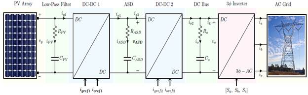
This section shows the design of the controllers that allow for energy management in the proposed microgrid (Figure 1). It consists of modular Buck-Boost converters and an ASD device, supervised via a master control. The control strategies for the solar array, the voltage regulation in the DC bus, and the control loops of the ASD system were tuned using SISOTOOL/MATLAB, whose design parameters are based on a minimum gain margin of 6 dB and a phase margin in the [30, 60]° range Ramirez-Murillo (2015).
To regulate the DC bus, this study considered the SH topology described in Ramirez-Murillo et al. (2014). Unlike that work, this research used an array of solar panels as a primary source, in which an MPPT algorithm was applied in order to ensure maximum power extraction. It is essential to highlight that the development of an on-grid-type microgrid requires the design of DC voltage control loops, in conjunction with controlling the active power injected into the grid via an inverter.
Modular converter
A Buck-Boost converter is a switched-mode converter whose output voltage can be higher, lower, or equal to the input voltage, as it can operate in three different modes: 1) Buck mode, where the input voltage is higher than the output voltage (V g > V o); 2) Boost mode, where the input voltage is lower than the output voltage (V g < V o); and 3) Buck-Boost mode, where the input voltage is approximately equal to the output voltage (V g ≈ V o) Ramirez-Murillo (2015). Among the advantages of this type of converter are a high power conversion efficiency and the capability to control input/output currents.
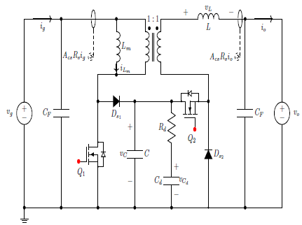
The converter consists of a Boost stage in cascade, connected with a Buck stage with magnetically coupled inductors, with an included damping network. The scheme of a Buck-Boost converter with current sensors is shown in Figure 2. The damping branch consists of a series of resistances R d and a capacitor CF connected in parallel to the capacitor CFBendib et al. (2015).
The averaged model of the converter is represented by a set of differential equations that consider the damping network and the turns ratio n = 1, as described in Erickson and Maksimovic (2007), where d1 and d2 correspond to the cycles of the switches Q
1
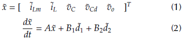
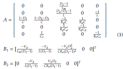
and Q2. Likewise, the overline in the variables corresponds to the average during a switching period. Likewise, linearizing the set of differential equations, in conjunction with the small-signal state vector given by Equation (1), the dynamic model is shown in Equation (2), where A is the state matrix, and B1 and B2 are the input vectors corresponding to  1
and
2
. The state matrices are presented in Equation (3) Restrepo et al. (2011).
1
and
2
. The state matrices are presented in Equation (3) Restrepo et al. (2011).
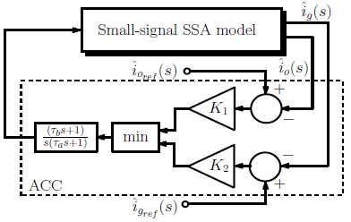
The transfer functions of the small-signal converter from the current control to the input/output current loops are presented in Figure 3. The corresponding parameters are Ta = 3, 3 μs, ть = 33 μs, K1 = 590 (sA)-1, and K2 = 1298 (sA)-1Restrepo et al. (2012).
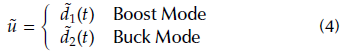
The control variable ũ shown in Figure 3 refers to the duty cycles of the MOSFETs of the modular converter, as seen in Equation (4).
DC bus voltage control loop design
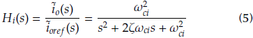
In addition to the small-signal current control loop described in the previous subsection, it is necessary to add a voltage control loop to regulate the converter input/output voltages in each module. The closed-loop transfer function is presented in Equation (5), where ω ci is the natural frequency, whose value is 2ϖ8 krad/s; and ζ is the damping factor, which corresponds to 0,44 Ramirez-Murillo (2015). These values were selected while aiming for the lowest damping factor and bandwidth values Restrepo et al. (2011).
The European Cooperation for Space Standardization (ECSS) provides an output impedance mask for the DC bus criterion, which allows for a 1 % variation in the voltage vo with a 50 % load disturbance io. This impedance is presented in Equation (6) Mourra et al. (2008).

The value of Co is calculated using Equation (7).
Here, ω 0 corresponds to the bus voltage loop cutoff frequency, where a small ESR value is obtained. A parallel capacitor array was proposed in order to obtain a capacity of 2,35 mF, with a series resistance of 11,8 mΩ. In addition, voltage regulation in the DC bus is performed by the voltage control loop shown in Figure (Figure 4).
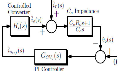
In the block diagram of Figure Figure 4, there is an algebraic simplification multiplying the numerator of the impedance Co by the additional pole of the controller G CVo (s). The DC bus impedance's closed-loop was adjusted on SISOTOOL with a bandwidth of 1, 29 kHz, obtaining a proportional gain of 20, 894 kAs/V and a time constant т equal to 890 μs.
Auxiliary storage device
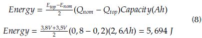
A simplified lithium-ion battery (LIR18650, 2, 6 Ah model) was used in this work EEMB (2010). This model took into account only the nominal region of the discharge capacity, from Q top to Q nom values. Here, the energy management algorithm always works between the voltage ranges of E top and E nom . The main advantage of this model is that it is easy to obtain the parameters from the datasheet provided by the manufacturer. In the linear region, the battery model can be modeled as an RC series branch with a SOC in the [20, 80] % range, where the C-value models the charging and discharging behaviors. The discharge behavior in the nominal region is required in order to size the energy storage. The area under the curve was obtained through Equation (8).
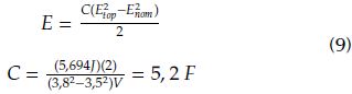
The value of the capacitor for one cell was calculated via Equation (9).
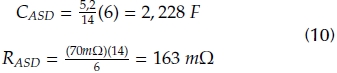
However, to obtain the reference voltage of 48 V, an array of six branches connected in parallel was proposed. Each branch contains 14 cells connected in series. The capacitor value was obtained from Equation (9) while the series resistor value comes from the datasheet provided by the manufacturer EEMB (2010). The equivalent RC series branch for the selected ASD is presented in Equation 10.
ASD control loop design
The battery impedances were calculated for the following loops: 1) a nominal or reference SOC (20 %), 2) a minimum SOC (4 %), and 3) a maximum SOC (80 %). This is presented in Equation (11), considering the criteria established by the ECSS.
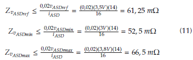
The controller parameters were obtained according to the previously mentioned DC bus impedance mask. The nominal and minimum SOC loops were adjusted while considering a bandwidth of 0, 00307 kHz, a proportional gain of 11,488 As/V, and a time constant т of 2,9 s. The maximum SOC loop was set with a bandwidth of 0, 00318 kHz, a proportional gain of 6,9632 As/V, and a time constant т of 5 s.
Maximum power point tracking loop
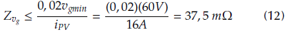
The panel filter has the same RC parameters C0 = C PV and Ro = R PV as the DC bus. However, the value of the impedance mask changes, as seen in Equation (12).
The PI controller parameters were adjusted via SISOTOOL with a 0, 903 kHz bandwidth, given a proportional gain of 11, 802 kAs/V and a time constant т of 1,1 ms. On the other hand, the MPPT control loop was tuned considering the P&O algoritm, where, if ΔV > 0, then the voltage is increased by 0, 1 V. On the other hand, if ΔV < 0, then the voltage is decreased by 0, 1 V Mohan et al. (2003).
Power sharing algorithm
A three-phase inverter is a key device for interfacing a DC system with an AC grid. The switching of the insulated-gate bipolar transistors (IGBTs) is performed by comparing each of the three current and voltage sine waves, which are obtained after the pulse-width modulation (PWM). These waves have a 120° phase shift, with the same triangular carrier signal and switching frequency of 15 kHz. Likewise, the output amplitude is determined by the ratio of the signal carrier to the modulator. The inverter output voltage requires a step-up transformer with a Delta-Star connection and a grounded neutral wire. Thus, the inverter will be able to inject any current level into the grid. On the other hand, the 230 V line's voltage regulation is achieved by modulating the pulse width to obtain the switching signals [Sa, Sb, Sc]. The design criteria are described below.
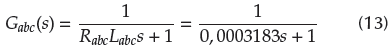
A series RL first-order low-pass filter is required to eliminate the transmission line current ripple. Its transfer function is presented in Equation (13). These parameters correspond to R abc and L abc .
The Park transform allows converting the sinusoidal values in time into steady-state values, and it is applied to both the filtered currents and the grid voltages. It is important to consider that the phase of the grid starts at t = 0 s. Likewise, this transform reduces the harmonic content of the output voltage in the inverter.
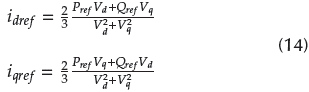
Active power control is carried out by calculating the reference currents through the network voltages in a steady state. The current references for the PI regulator are obtained via Equation (14) from the active and reactive power reference values, which corresponds to P (16)(48) W = 768 W and Q ref = the voltage references vd and vq.
The PI controller was adjusted using the SmartCtrl tool of PSIM. The GM of the PI controller and the BW were set to 45,33° and 478,63 Hz, respectively.
Results
Constant load under variations in the irradiance profile
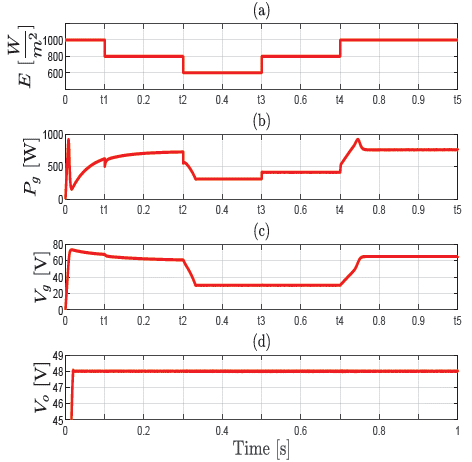
In this subsection, three control loops are designed and validated: first, the DC bus voltage is regulated at V oref = 48 V using a reference current i oref2 ; second, the panel minimum voltage is regulated at V gmin = 30 V through i gref1 and the MPPT algorithm; finally, the ASD VASDref = 48 V nominal voltage is also controlled by applying the i gref1 signal. These control input currents regulate the voltages vg and vo in the distribution system shown in Figure 5. In this simulation, a constant commercial load value of 3, 3 Ω, 698 W was obtained.
In Figure 5a, an amplitude-varying irradiance profile is depicted, considering values of [600, 1000] W/m2. During the interval from 0 to t1, the PV array fully supplies the power demand, as shown in Figure 5b. However, when the irradiance decreases at t 1 = 100 ms, the array cannot supply all the power required. Therefore, the ASD supplies the power shortage demand. This system continues supplying power from t1 to t2, while the power demand increases. Subsequently, in the intervals from t2 to t3 and from t3 to t4, the PV array power is set to a reference, at 310 and 414 W, which corresponds to irradiance levels of 600 and 800 W/m2, respectively. Finally, from t4 to t5, once the system reaches the maximum irradiance value of 1000 W/m2, the PV array power stabilizes at a constant power demand. It is observed that, from 0 to t4, the maximum PV power is supplied. Moreover, from t4 to t5, the total power required by the load is delivered by the ASD, and the energy management algorithm prioritizes the ASD nominal voltage control loop at V ASDref = 48 V.
In Figure 5c, once the irradiance decreases, the voltage also decreases, until it stabilizes at V gmin = 30 V, as shown for the time interval from t2 to t4, which regulates the PV array voltage at the minimum operating value. On the other hand, from t4 to t5, when the irradiance increases to 1000 W/m2, the panel voltage reaches 65 V in order to provide the total demanded power. In Figure 5d, the DC bus voltage behavior is shown at the reference value of V oref = 48 V and under a 3, 3 Ω constant load, maintaining this state regardless of variations in demanded power and irradiance.
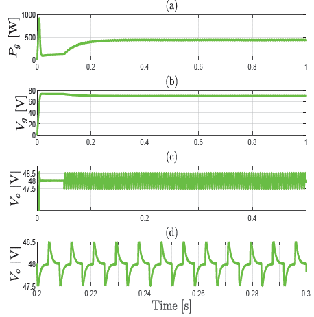
Impedance-varying load profile under a constant irradiance condition
In this scenario, two control loops are validated: first, the DC bus voltage regulation loop at V oref = 48 V through I oref2 ; and second, the ASD nominal voltage regulation at V ASDref = 48 V using I gref1 and the MPPT algorithm. These control loops are tested while considering a constant impedance load of 20 Ω, adding a variable impedance load of 3, 9 Ω.
Figure 6a shows that, under a constant irradiance of 1000 [W/m2], the input power is stabilized at 410 W. Moreover, in Figure 6b, the output voltage Vg is stabilized through the MPPT algorithm, reaching the maximum power point and with no significant increases or decreases in the input voltage. Figure 6c validates the DC bus voltage regulation loop. Finally, in Figure 6d, there are DC bus voltage ripples of 1 V throughout 0, 1 s. This disturbance in the load represents a demanding scenario, with 76, 92 % of the maximum power, which corresponds to 768 W.
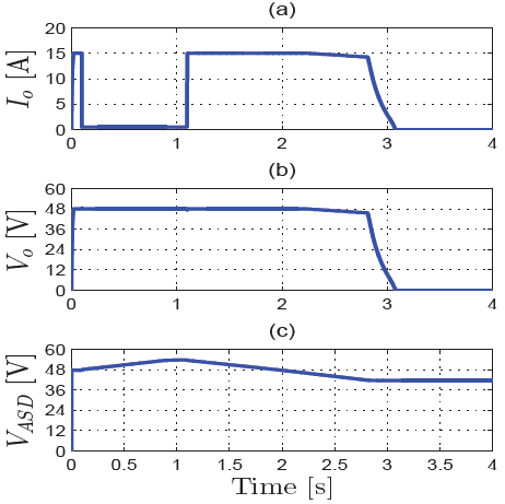
ASD loops scenario test
In this scenario, three control loops are validated: the DC bus voltage, which has been widely considered in the previous subsections; the ASD minimum voltage at V ASDmin = 42 V using I gref2 ; and the ASD maximum voltage at V ASDmax = 53, 2 V using I oref1, which implies an MPPT algorithm failure.
Figure 7a shows a saturation of the current reference 7gref1 = 16 A, with an initial constant load of 3, 2 Ω until t = 0, 1 s. Then, from t = 0, 1 to t = 1, 1 s, the maximum ASD voltage VASDm„x exhibits the required performance, while a load shedding is deployed, considering a constant load of 100 Ω. On the other hand, from t = 1, 1 s onward, the load is fully reconnected and shows an adequate behavior in the current output. Finally, Figure 7b shows the DC bus voltage drop V oref , while the ASD minimum reference voltage V ASDmin achieves the reference value in Figure 7c.
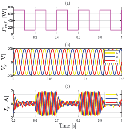
Inverter considering the DC system dynamics
In this scenario, the dynamics of the DC system are included using a square signal, whose maximum and minimum values correspond to 768 and 115, 2 W, respectively. This profile is shown in Figure 8a, whuch includes the active power control loop mentioned in the previous section. Figures 8b and 8c illustrate the three-phase voltages (Vg = [va, vb, vc]T) and currents (Ig = i a , i b, i c ]T) after considering the DC dynamics.
Discussion
In the previous section, the results obtained for the microgrid were compared with the findings of another study Rajanna (2022), where it was observed that the maximum and minimum SOC of the ASD were not regulated, thus requiring the incorporation of additional protection loops. Furthermore, another recent work Srikanth Goud and Sekhar (2023) highlighted the absence of an ASD. To address these limitations, this study focused on establishing parameters for the protection and operation loops of the ASD. Additionally, an energy management algorithm with an increased number of control loops was designed, using a versatile modular Buck-Boost converter. To regulate the voltages of the buses while considering the power variations, the design of the control loops in the DC stage employed the impedance mask criterion. Moreover, the injection of active power into the AC grid was regulated through the dq model of the inverter. As a remark, the P&O algorithm was integrated into the control loop that regulates the voltage Vg.
Other recent works Zhou et al. (2022); Shang et al. (2020) explored the optimization of ASDs in microgrids. These studies proposed a novel approach that integrates machine learning techniques with power management algorithms to enhance the efficiency and performance of ASD. Reinforcement learning techniques proved to be effective through simulations and experimental validations, exhibiting significant improvements in energy management and system performance Ali et al. (2021).
Conclusions
The main contribution of this research is the design of a series hybrid (SH) topology for a PV distribution system, using two modular Buck-Boost converters.
Source: Authors
Figure 8: (a) Reference power from DC dynamics, (b) three-phase voltages, and (c) three-phase currents
These converters allow designing an energy management algorithm, where MPPT, nominal SOC, and maximum ASD SOC control loops are considered for the first module. Likewise, the second stage ensures the minimum SOC and the DC bus voltage reference, as shown in the simulation results. Four test scenarios were proposed to validate the correct operation of the system control loops.
The ASD simplified model drives a suitable transient and shows a steady-state behavior. As a result, when the microgrid is connected to the AC grid (on-grid), the designed energy management scheme allows supplying the demand under irradiance variations. The power injected into the AC grid is controlled using a three-phase inverter, but its waveform is distorted. Therefore, it is recommended that a harmonic compensation device be introduced, such as passive or active filters, line reactors, and hybrid filters, among others.
The impedance mask criterion allows appropriately designing classical controllers for voltage regulation in DC buses, wherein the impedance is modeled. Likewise, the modular converter used in this research facilitates voltage regulation, as it allows for input/output current control with a higher bandwidth. The interaction between these loops does not entail any conflict, given that their control hierarchy goes hand in hand with the lowest energy consumption in the system.

