Serviços Personalizados
Journal
Artigo
Indicadores
-
 Citado por SciELO
 -
 Acessos
Links relacionados
-
 Citado por Google
 -
 Similares em
SciELO
 -
 Similares em Google
Compartilhar
Revista Facultad de Ingeniería Universidad de Antioquia
versão impressa ISSN 0120-6230versão On-line ISSN 2422-2844
Rev.fac.ing.univ. Antioquia n.37 Medellín jul.set. 2006
Revista Facultad de Ingeniería N.o 37. pp. 115-128. Julio, 2006
Abstract
The fixation of bone replacement implants to the hosting tissue can be improved if the implants have a bioactive surface that can precipitate hydroxyapatite in vivo. Titanium alloys, despite their desirable mechanical and nontoxic properties, are not bioactive and, therefore, do not bond directly to the bone. One of the ways to change a bioinert metallic surface is to coat it with a bioactive material. This work presents the evaluation of the fatigue behaviour by Hertzian (spherical) indentation of a glass coating on Ti6Al4V. This coating belongs to the SiO2-CaO-MgO-Na2OK2O-P2O5 system and, despite it can be used for corrosion protection, it has been specifically designed to be used as the inner layer of a bioactive bilayer coating with an outer layer of lower SiO2 content to ensure bioactivity. Hertzian monotonic tests allowed to obtain a damage sequence starting with three brittle damage events (ring, cone and radial cracking) followed by coating delamination associated to the plastic deformation of the substrate. The first brittle damage, ring cracking, was used as criteria for the evaluation of the stress-corrosion and cyclic loading cracking behaviour in air and in distilled water environments. Results showed sensitivity of the coating to degradation under both static and cyclic loadings which was considerably larger in distilled water due to the corrosion susceptibility of this glass. Delamination damage was also sensitive to Hertzian cyclic loading showing two different mechanisms depending of the maximum applied load.
---------- Key words: Hertzian indentation; Cyclic contact fatigue; Sintered glass coating; Biomedical applications.
Comportamiento a la fatiga de un recubrimiento de vidrio en Ti6AL4V para aplicaciones biomédicas
Resumen
La fijación al tejido receptor de implantes para el reemplazo de hueso puede ser mejorada si poseen una superficie bioactiva con la capacidad de precipitar hidroxiapatita in vivo. Las aleaciones de titanio, a pesar de sus buenas propiedades mecánicas y comportamiento no-tóxico, no son bioactivas y, por tanto, no se enlazan directamente al hueso. Una de las maneras de modificar una superficie metálica bioinerte es recubriéndola con material bioactivo. En este trabajo se presenta la evaluación del comportamiento a fatiga mediante indentación hertziana (esférica) de un recubrimiento de vidrio sobre Ti6Al4V. Este recubrimiento pertenece al sistema SiO2-CaO-MgO-Na2O-K2O-P2O5 y, a pesar de que puede usarse para protección contra la corrosión, ha sido específicamente diseñado para ser utilizado como capa interna de un recubrimiento bicapa bioactivo con una capa externa de bajo contenido en SiO2 para garantizar la bioactividad. Los ensayos hertzianos monotónicos permitieron obtener una secuencia de daños comenzando con tres eventos de daño tipo frágil (agrietamiento tipo anillo, cono y radial) seguidos por la delaminación del recubrimiento asociada a la deformación plástica del substrato. El primer daño frágil, el agrietamiento tipo anillo, fue usado como criterio para la evaluación del agrietamiento por corrosión bajo tensión y por carga cíclica, en aire y agua destilada. Los resultados mostraron la sensibilidad del recubrimiento a la degradación bajo ambos tipos de carga, estática y cíclica, siendo esta degradación considerablemente mayor en agua destilada debido a la susceptibilidad del vidrio a la corrosión. La delaminación fue también sensible a la carga cíclica hertziana presentando dos mecanismos diferentes dependiendo de la máxima carga aplicada.
---------- Palabras clave: indentación hertziana, fatiga cíclica por contacto, recubrimiento de vidrio sinterizado, aplicaciones biomédicas.
Introduction
Several important characteristics associated with Ti and Ti-based alloys —especially the balance between mechanical properties, chemical resistance, and nontoxicity— make these alloys one of the most important materials for hard tissue replacement [1]. However, once implanted, they become encapsulated by a dense fibrous tissue, which can result in an interfacial failure and loosening of the implant [2]. A surface modification of the metallic implants using a bioactive material as synthetic hydroxyapatite (Ca10(PO4)6(OH)2) has been proposed to solve this problem [3]. Several studies investigating the performance of these coatings have revealed good short-term adhesion to the bone with a poor long-term interfacial stability between the coating and the substrate [4]. An alternative method is to coat the metallic implants with a bioactive glass that can precipitate hydroxyapatite in vivo, optimizing at the same time the adhesion to the substrate. The first attempts to obtain a bioactive glass coating on Ti6Al4V by enamelling, immersion in molten glass, or plasma-spray were unsuccessful because of cracking caused by stresses associated with thermal expansion mismatch between the substrate and the coating [5]. A simple technique for applying improved bioactive coatings on Ti-based alloys, using glasses of the SiO2-CaOMgO-Na2O-K2O-P2O5 system, was successfully developed at Lawrence Berkeley National Laboratory (LBNL) [6-8]. The chemical composition of the glasses is based on the Bioglass® developed by Hench et al. [9], with increased SiO2 content, and partial substitution of the original K2O and MgO with Na2O and CaO, respectively.
These changes were done in order to reduce the coating thermal expansion coefficient so that it would be closer to that of the substrate.
The evaluation of the intrinsic mechanical properties of a coating is a very difficult task by traditional methods. The Hertzian (spherical) indentation method has inherent advantages for mechanical characterization of coatings because of its simple test configuration with small specimens required and also because its suitability for studying pure elastic contact following the evolution of damage modes as a transition to full plasticity [10]. Previous works have shown that the Hertzian indentation is a powerful tool to simulate some biomechanical loading conditions, specifically the basic elements of occlusal [11] and part of the hip function [12] . It is also well known that concentrated loads, static and cyclic, of characteristic radius are responsible of the degradation of ceramics once implanted by creating and propagating cracks [13].
Therefore, the aim of this work is to characterize the mechanical response of the glass coating to Hertzian monotonic test and use the damage modes observed as criteria to evaluate the sensitivity to static and cyclic loading. This paper is arranged in the following sequence. A description of the coating preparation, characterization techniques and mechanical testing is presented in Section 2. Microstructural characterization results are showed in Section 3.1. Damages modes produced during a monotonic test are presented in Section 3.2. The sensitivity of this cracking to static and cyclic loads is described in Sections 3.3 and 3.4 respectively. Delamination by cyclic loading is presented in Section 3.5. The paper concludes in Section 4 with a summary of the salient findings of this work.
Experimental procedure
Sample preparation
The coatings were obtained using a conventional enamelling method [6-8]. The starting glasses were obtained by mixing the appropriate reagents (SiO2: 99,5%, Cerac; CaCO3: 99,9%, JT Baker; MgO: 98,6%, JT Baker; K2CO3: 99,0%, Allied Chemical; NaHCO3: 99,5%; JT Baker; and NaPO3: 99,7% Allied chemical) in ethanol using a high-speed stirrer to achieve the desired composition for each glass (table 1). The mixture was first dried at 80 °C for 12 h and then air-fired at temperatures ranging from 1.400 °C to 1.500 °C for 4 h in a Pt crucible. The melt was cast into a graphite mould to obtain glass plates ( ~ 50 x 50 x 5 mm) that were subsequently annealed at 500 °C for 6 h to relieve stresses and then milled in a planetary agate mill. To obtain the coatings, a suspension of the glass powder (particle size < 20 μm) in ethanol was deposited on Ti6Al4V beams (99,0% purity, 45 x 5 x 4 mm), which had been previously polished with diamond (1 μm particle size) and cleaned in ultrasonic baths of acetone and ethanol. Afterwards, the coatings were air-dried at 75 °C overnight and fired at temperatures ranging from 800 °C to 820 °C for a short time (around 1s). Finally, the coatings were quenched in air. The initial beams were sectioned into samples of 5 x 3 x 4 mm
Table.1. Chemical composition of the glass coating.
Microstructural characterization
Coating thickness was measured using optical microscopy by observations of the cross-section. This method was also used to observe the coating microstructure revealed after acid etching (10 ml HNO3, 6 ml HF and 80 ml H2O). SEM and EDS analysis was also performed on the samples surface and cross-sections. Coating porosity was estimated by surface image analysis.
Mechanical testing
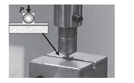
The coating roughness parameters (Ra = profile deviations mean and S = mean space between the profile peaks) were measured with a Surftest SV- 502 bidimensional surface tester with a diamond stylus. According to the measured parameters (Ra = 0,21 μm ; S = 110,60 μm , it was considered that the surface of the substrate, polished with diamond suspension of 1 μm particle size, ensures a coating surface suitable to be indented without polishing. The Hertzian monotonic tests were carried out with WC-Co spheres using an universal electromechanical Instron machine (model 8.562) with a 1 kN load cell. Mechanical set-up is presented in figure 1. The radius of the spheres was 1,25 mm and the monotonic applied load rate used was 2 Ns-1. The stress-corrosion cracking tests were performed in ambient air (relative humidity ~40%) and distilled water by applying constant loads lower than the critical one to produce the first brittle damage (ring crack) during the monotonic test. Afterwards, the critical time for ring crack formation was observed by optical microscopy immediately after the load was removed. The sensitivity of ring cracking to cyclic loading was evaluated by applying the same maximum loads as for the stress-corrosion tests by using a servo-hydraulic Instron machine (model 8500). The cyclic loading was applied in sinusoidal wave-form at frequency, f = 10 Hz. A load ratio (R = Pmin/Pmax) of 0,2 was studied. The number of cycles to produce the ring crack, Nf, was determined by optical microscopy as in the stress-corrosion case. All tests were performed in the same environments as before. The ring cracks generated from the cyclic tests were observed by SEM. Delamination under cyclic loading was studied by applying fractions of the critical load to produce the damage during the monotonic test. The cyclic loading was applied by using the same wave and frequency as for cyclic ring cracking and the load ratio was also 0,2. The damage produced was determined in the same manner as above. Possible residual imprint in the metallic substrate due to the plastic deformation was verified by removing the coating through elastic bending of the specimens.
Results and discussion
Microstructural characterization
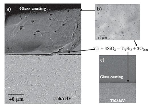
The first physical feature of the coating observed by optical microscopy (figure 2(b)) is a surface porosity of about 5%. These pores are the conse
Figura 1 Mechanical set-up for the Hertzian indentation test
quence of both the oxygen bubbles of the reaction between Ti and SiO2 at the interface to produce an interfacial layer of Ti5Si3 (figure 2(c)), and the air trapped between the glass particles after sintering [14]. The coating cross-section in the same figure shows that the pores are confined at the top of the coating. The microstructure observed by SEM after acid etching of the coatings’ cross-section (figure 2(a)) is the result of preferential etching at the boundaries between sintered glass particles due to the higher dissolution rates in these areas. Previous studies have reported a phosphate, 2,4CaO·0,6Na2O·P2O5, as the crystalline phase in the coating [6-8]. The amount of this phase determined by the diffraction peaks integration method [14] was between 3-6% vol. The microstructure revealed in the substrate (figure 2(a)), is composed by grains of α phase in a matrix of plates of α surrounded by β phase, characteristic of a mill-annealed alloy. The thickness of the coatings, measured by optical microscopy observations of the cross-section, was approximately 40 μm.
Figure 2 Microstructural features of the coating: (a) Cross-section polished and etched; (b) Top view; (c) Crosssection polished with energy dispersive spectrometry (EDS) mapping of Ti
Hertzian indentation damages modes
The damage modes of this porous glass coating on a metallic substrate with a difference of
elasticity such that Ec > Es, are presented in the following sequence (figure 3):
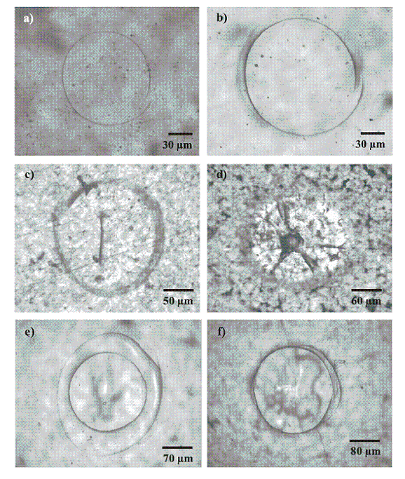
1. Ring cracking at a load for which a pre-existent surface flaw “runs around” to form a shallow ring (figure 3(a)). The surface flaw is located close to the contact perimeter over which acts the maximum stress intensity factor.
Figure 3 Optical micrographs of different damages that appear in the coating for increasing Hertzian monotonic loads: (a) Ring crack, P = 48 ± 2 N; (b) Cone crack, P = 52 ± 2 N; (c) Radial crack from the interface, P = 55 ± 2 N; (d) Delamination, P = 60 ± 3 N; (e) Secondary ring crack, P = 65 ± 5 N; (f) Radial cracks reaching the surface, P = 70 ± 5 N
2. Cone cracking happens when the increasing load reaches a second critical value and the ring begins to flare out into the frustum of a cone (figure 3(b)). The trajectory of this crack follows closely the σ3 one, nearly normal to the principal tensile stress, σ1, in the prior stress field.
3. Radial cracking then appears from the interface on the central contact axis due to the maximum biaxial bending stress that acts over this axis which is induced due to the plastic deformation of the substrate (figure 3(c)). In fact, this later damage is actually the first one of the coating/substrate system and it happens for a load of around 10 N which is observed from the shear stress distribution inside the indented specimen [15].
4. For higher loads, it appears a pattern of decomposed spectra of white light when the interface is focused with the microscope (figure 3(d)). This event corresponds to the delamination of the coating which is the consequence of the shear stress induced by the plastic deformation of the substrate and enhanced by the presence of the radial cracks in the coating.
5. Secondary cone crack is generated outside the first cone for higher loads, because the expanding contact circle engulfs the previous cracks (figure 3(e)). For increasing loads some radial cracks can reach the outer surface of the coating (figure 3(f)).
The mechanism of ring and cone cracks formation is already well characterized in the literature [16, 17] as well as the corresponding to radial cracks [18, 19]. Hertzian delamination was observed by Fisher-Cripps et al [20} in a Al2O3:40 wt% TiO2 coating on an steel substrate. They found that delamination occurred during the unloading part of the test because of the plastic deformation of the substrate. Here it is presented a situation in which delamination takes place in a glass/metal system, which has not been reported yet. In this case, plastic deformation of the susbtrate is also the responsible of the coating delamination as was confirmed by post-indentation elastic bending of an indented beam. However, according to the interference pattern observed at the interface in figure 3(d)(Newton´s rings) and its evolution for increasing loads, the shear stress induced at the upper points of the residual imprint in the substrate has the main role in delamination process.
Stress-corrosion cracking
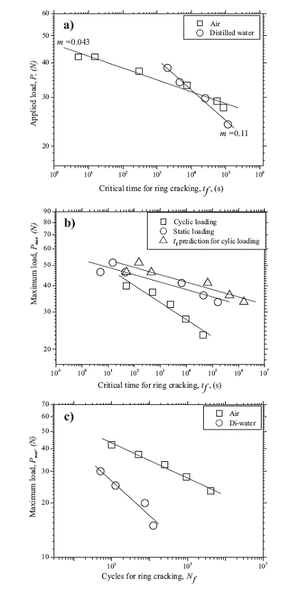
Figure 4(a) presents the plots of constant applied loads in terms of the time to produce the ring crack in air and distilled water. Degradation of the coating under static loading is evidenced as the ring crack is formed for loads lower than the critical one determined during the monotonic test.
It is clear that lower applied loads require longer contact times to cracking and, as it was expected, static loading degradation is stronger in distilled water as can be drawn from the steeper slope of the curve. Glass degradation under static load in presence of moisture is a well-known phenomenon especially in high silica glasses [21]. It is normally attributed to the hydrolysis reaction in which silicon-oxygen bonds ahead of a crack tip are broken by water molecules enhanced by the straining due to the stress field induced there
[22]. This degradation is strongly dependent of the active specie concentration that can access to crack tip [23]. This explains the stronger effect in distilled water observed in figure 4a. The different ring crack morphology produced in each environment confirms this influence (figure 5). From figure 4ais evident that the relationship between the constant applied load, Pmax, and the time to failure (ring crack), tf, is given by:

where m is the exponent of the ring crack formation which is the slope of the curves in figure 4(a). This is the typical relationship which describes the degradation under static loads in many ceramics and glasses [24]. Note that the ratio between the experimental values of m in water and in air is mH2O/mAir 3. This value is consistent
Figure 4 Set of curves of ring cracking under Hertzian static and cyclic loading: (a) Stress-corrosion ring crackingin air and in distilled water; (b) Comparison between cyclic and static loading in air, including the predicted time to failure under cyclic loading; (c) Comparison between cyclic loading cracking in air and in distilled water
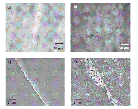
Figure 5Ring cracks morphologies from Hertzian static loading tests: (a) and (b) optical micrographs from tests in air and distilled water, respectively; (c) and (d) SEM micrographs with a detail of the cracks in (a) and (b)
with that one which can be calculated from the conventional crack velocity exponents reported in the literature: nAir = 30 - 40 [25] and nH2O = 10 - 15 [23]. Note that the higher conventional crack velocity exponent implies a lower subcritical crack growth rate.
Ring cracking by Hertzian cyclic loading
Figure 4(b) presents the comparison between the time to ring cracking in air under static loading due to the stress- corrosion and due to the cyclic loading. It is also presented the curve corresponding to the prediction of time to failure under cyclic conditions, based on the knowledge of the crack velocity under stress-corrosion. This curve was plotted by assuming that failure under cyclic as well as static loading is caused by the same flaw population and that is dominated by the same crack growth mechanisms [26].
Indeed, with the above assumptions it can be demonstrated that:

where tc and ts are the times for crack growth up to certain length (ring crack formation) under cyclic and static loading and h is a function which depends on the shape of the cyclic loading waveform, static loading crack velocity exponent, n, and the load ratio during the cyclic test, R. Then, for R = 0,2, the Pmax range used and the crack velocity exponent under static loading, n h 0,1. It can be noted in figure 4(b)that the coating under cyclic loading presents ring cracking much faster than under static loading, by calculating the failure time under cyclic loading from the expression t = N/f, indicating the existence of a cyclic fatigue effect. This cyclic degradation is also confirmed by comparing with the curve for the predicted time to failure under cyclic loading (tc 10 ts) which shows that the expected time is much longer than the time calculated from the experimental data.
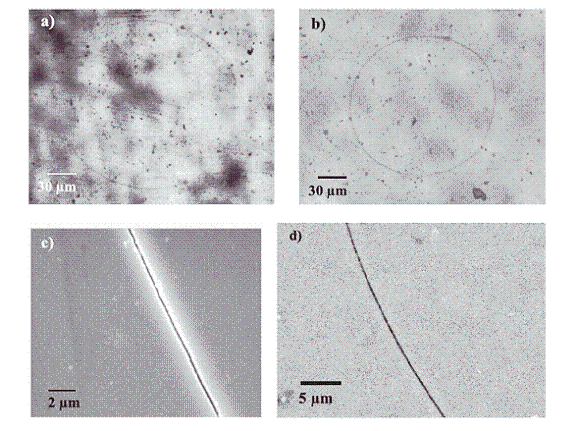
Therefore, despite this coating is glass-based, there is a stronger degradation under cyclic loads, indicating that the degradation effect is not due to stress-corrosion solely. This result implies mechanisms which are at least partially different from those which act under static loading. By looking in detail at the ring crack produced under static loading (figure 5(c)), it can be appreciated that the crack is sharp and “clean” which is a typical feature of a stress-corrosion crack in a common glass. By contrast, figure 6(c)shows that the cyclic ring crack path is more tortuous with debris between the crack wake surfaces.
These debris particles indicate the presence of a microcracked tip damaged zone [27]which is the consequence of the microfracture of the necks between the glass sintered particles (figure 2(a)). The debris particles are produced because of the oscillating shear stress which generates a frictional wear sliding. They act against the shielding mechanism initially present due to the microcracks and, therefore, the crack tip will be under a larger “effective” stress intensity factor, Keff, locally reaching the critical value for the crack growth, KIc. This growth becomes subcritical because the stress intensity factor at the
surface ring crack, KIB, decreases.
Figure 6 Ring cracks morphologies from Hertzian cyclic loading tests: (a) and (b) optical micrographs from tests in air and distilled water, respectively; (c) and (d) SEM micrographs with a detail of the cracks in (a) and (b)
The above allows establishing the difference in degradation mechanisms of the sintered glass coating under static and cyclic loading: in the former, the sharp and straight crack is “transgranular” following the path of the Si-O-Si strained bonds which are located preferentially at the bulk of the glass particles. By contrast, the crack path from cyclic loading is mostly “intergranular” due to the effect of debris between microcraks (located at the sintered particles boundaries). The difference in the mechanisms can be observed more clearly by comparing the rings crack morphology from cyclic loading in air and in distilled water (figures 6(c) and 6(d)).
Delamination due to the Hertzian cyclic loading
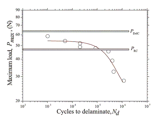
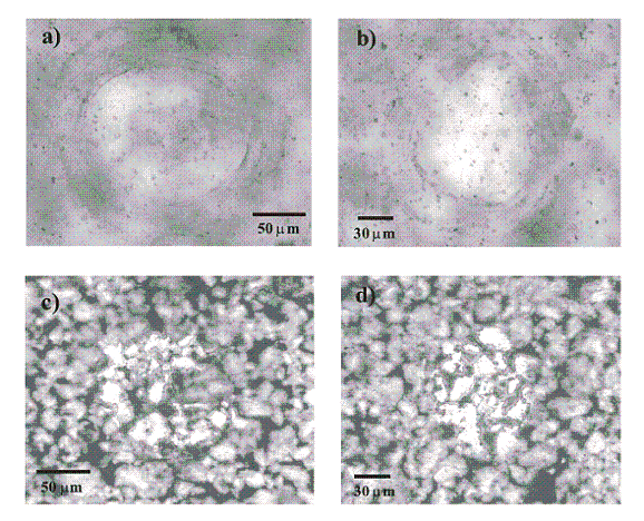
The maximum applied load, Pmax, as a function of the number of cycles to produce the first delamination for a constant load ratio, R = 0,2, is shown in figure 7. This curve illustrates that delamination is sensitive to Hertzian cyclic loading. Note that the curve shows peculiar fatigue behaviour, having two different slopes, with the steeper one occurring at larger number of cycles, with an inflexion point (“knee”) close to the critical load for radial cracking, PRc. Pictures of the top and of the interface of the coating after delamination in each regime of the curve are depicted in figure 8. The top views show that the surface damages are similar with the exception that the corresponding to the lower slope regime (Pmax > PRc) present cone cracking because Pmax is also higher than the critical load for this damage, Pcc. With respect to the delamination morphology, for Pmax > PRc, it is similar as under a monotonic load with the presence of radial cracks. However, the delamination for Pmax < PRc it is not accompanied by any radial crack and the colour pattern is mostly white. This indicates that the separation film between the coating and the substrate is very thin. Post-indentation bending showed that in both regimes there was plastic deformation of the substrate. Therefore, from the fatigue curve of figure 7and the associated delamination morphologies (figure 8) it can be inferred the following:
Figure 7 Maximum applied load, Pmax, in terms of the cycles number to delaminate during a Hertzian cyclic test for R = 0,2
Figure 8Damage morphology produced due to cyclic loading of the coating: (a) and (b) Top views for Pmax = 52 N (Pmax > PRc) and Pmax = 32,5 N (Pmax < PRc), respectively; (c) and (d) Interfacial (delamination) views for Pmax of (a) and (b), respectively
1. For the load range where Pmax > PRc, cyclic delamination takes place because the plastic deformation of the substrate is large enough to allow acting the shear stress at the outer area of the substrate imprint, enhanced by the presence of the radial cracks.
2. For Pmax < PRc, the responsible of the delamination appears to be the plastic deformation of the substrate (no radial crack) and the subsequent elastic recovery of the coating during unloading. It is not clear yet if delamination within this load range is the result of a cyclic interfacial crack growth or it simply occurs during the unloading part for a certain critical size of the substrate plastic deformation.
Conclusions
According to the mechanical response of the coating to Hertzian indentation the following conclusions can be drawn:
1. Hertzian monotonic tests allowed to obtain a damage sequence starting with three brittle damages (ring, cone and radial cracking) followed by delamination associated with the shear stress induced by the plastic deformation of the substrate and the presence of radial cracks.
2. Hertzian static loading tests showed that the coating presents the typical stress-corrosion
cracking behaviour of a common high silica glass. The sensitivity in air and distilled water determined by this method was consistent with results reported in literature.
3. Despite being a glass coating, comparison between static and cyclic Hertzian loading tests revealed that it suffers cyclic fatigue degradation. The mechanism of this degradation is mainly the reduction of the microcracking shielding which was confirmed by the presence of debris between the crack wakes. This indicates the existence of crack tip damaged zone which is the result of the microcracks associated with the sintered character of the glass coating.
4. Delamination damage is sensitive to Hertzian cyclic loading. The different delamination morphology depending of the maximum load has allowed to propose two different mechanisms: when the maximum load is larger than the critical one to radial cracking the damage is caused by the shear stress due to the substrate deformation and facilitated by the radial cracks; while for lower maximum loads, without any radial crack, the damage is the consequence of the elastic recovery of the coating after the plastic deformation of the substrate.
5. The above results demonstrates that the Hertzian indentation method can be used satisfactorily for the mechanical characterization of the coating and also for life prediction under static and cyclic contact loads which is an important feature for biomedical applications.
Acknowledgments
This work is supported by the Spanish Ministry of Science and Technology through Grant No. MAT202-00368 and the National Institutes of Health/National Institutes of Dental and Craniofacial Research through Grant No. IR01DE11289. J. Pavón wishes to thank Colciencias-Colombia for financial sponsorship of his Ph.D. studies.
References
1. H.S. Dobbs. “Fracture of titanium orthopaedic implants”. J. Mater. Sci. Vol. 17. 1982. pp. 2398-2404. [ Links ]
2. L. L. Hench. “Bioceramics: from concept to clinic”. J. Am. Ceram. Soc. Vol. 74. 1991. pp. 1487-1510. [ Links ]
3. W. Suchanek, M. Yoshimura. “Processing and properties of hydroxiapatite-based biomaterials for use as hard tissue replacement implants”. J. Mater. Res. Vol. 13. 1998. pp. 94-117. [ Links ]
4. W. R. Lacefield. Hydroxilapatite coating. In An Introduction to Bioceramics, ed. Hench, L.L. and Wilson, J. World Scientific, Singapore, 1993, pp. 223-238. [ Links ]
5. T. M. Lee, E. Chang, B. C. Wang, Y. C. Yang. Characteristics of plasma-sprayed bioactive glass coatings on Ti6Al4V alloy: an in vitro study. Surface Coatings Technology. Vol. 79. 1996, pp. 170-177. [ Links ]
6. J. M. Gómez-Vega, E. Saiz, A. P. Tomsia. “Glass-based coatings for titanium implant alloys”. J. Biomed. Mater. Res. Vol.46. 1999. pp. 549-559. [ Links ]
7. A. Pazo, E. Saiz, A. P. Tomsia. Silicate glass coatings on Ti-based implants. Acta. Mater. Vol. 46. 1998.pp. 2551-2558. [ Links ]
8. A. Pazo, E. Saiz, A. P. Tomsia. Bioactive coatings on Ti and Ti6Al4V alloys for medical applications. In Ceramic Microstructures: Control at Atomic Level, ed. Tomsia, A.P. and Glaeser, A.M. Plenum Press. Berkeley. 1998. pp. 543-550. [ Links ] 9. L. Hench, R. J. Splinter, W. C. Allen, T. K. Greenlee. Bonding mechanism at the interface of ceramic prosthetic materials. Part 1. J. Biomed. Res. Symp. Vol. 2. 1971. pp.117-141. [ Links ]
10. B. R. Lawn. “Indentation of ceramics with spheres: A century after Hertz”. J. Am. Ceram. Soc. 81. 1998. pp. 1977-2071. [ Links ]
11. R. DeLong, W. H. Douglas. “Development of an artificial oral environment for the testing of dental restoratives: biaxial force and movement control”. J. Dent. Res. 62.1983. pp. 32-36. [ Links ]
12. A. W. Eberhardt, J. L. Lewis, L. M. Keer. “Normal contact of elastic spheres with two elastic layers as a model of joint articulation” ASME J. Biomed. Eng., 113. 1991. pp. 410-417. [ Links ]
13.I. M. Peterson, A. Pajares, B. R. Lawn, V. P. Thompson, E. D. Rekow. “Mechanical characterization of dental ceramics using Hertzian contacts”. J. Dent. Res. 77. 1998. pp. 589-602. [ Links ]
14. J. Pavón, E. Jiménez-Piqué, M. Anglada, S. López-Esteban, E. Saiz, A. P. Tomsia. “Stress-corrosion cracking by indentation techniques of a glass coating on Ti6Al4V for biomedical applications” J. Eur. Ceram. Soc., in press (on-line). [ Links ]
15. J. Pavón, E. Jiménez-Piqué, M. Anglada, E. Saiz, A. P. Tomsia. “Delamination under Hertzian cyclic loading of a glass coating on Ti6Al4V for implants” J. Mat. Sci. (Special Issue 6th Int. Workshop on Interfaces), submitted. [ Links ]
16. F. C. Frank, B. R. Lawn. “On the theory of Hertzian fracture” Proc. R. Soc. Lond., A 299. 1967. pp. 291-306. [ Links ]
17. P. D. Warren. “Determining the fracture toughness of brittle materials by Hertzian indentation”. J. Eur. Ceram.Soc. 15. 1995. pp. 201-207. [ Links ] 18. H. Chai, B. R. Lawn, S. J. Wuttiphan. “Fracture modes in brittle coatings with large interlayer modulus mismatch” J. Mat. Res. 9. 1999. pp. 3805-3817. [ Links ] 19. Y. W. Rhee, H. Kim, Y. Deng, B. R. Lawn. “Contact induced damage in ceramic coatings on compliant substrate: fracture mechanics and design”. J. Am. Ceram. Soc. 84 2001. pp. 1066-1072. [ Links ] 20. A. Fischer-Cripps, B. R. Lawn, A. Pajares, L. Wei. “Stress analysis of elastic-plastic contact damage in ceramic coatings on metal substrate”. J. Am. Ceram. Soc. 79. 1996. pp. 2619-2625. [ Links ] 21. S. M. Wiederhorn. In: Fracture Mechanics of Ceramics, Bradt RC, Hasselman DPH and Lange FF, editors. New York: Plenum, 1974. pp. 613. [ Links ] 22. Michaelske, T. A., Freiman, S. W. “A molecular mechanism of stress corrosion in silica” J. Am. Ceram. Soc. 66.1983. pp. 284. [ Links ] 23. B. R. Lawn. Fracture of brittle solids, 2nd Ed., Cambridge University Press, Cambridge, 1993, p. 249. [ Links ] 24. H. Mould, R. D. Southwick, “Strength and static fatigue of abraded glass under controlled ambient conditions” J. Am. Ceram. Soc. 42. 1959. pp. 582-592. [ Links ] 25. C. Barry, P.S. Nicholson. “Stress-corrosion cracking of a bioactive glass”. Adv. Ceram. Mater. 3. 1998. pp. 127-130. [ Links ] 26. A.G. Evans, E.R. Fuller. “Crack propagation in ceramic materials under cyclic loading conditions”. Metall. Trans. 5. 1974. pp. 27-33. [ Links ] 27. R. Dauskardt, R. O. Ritchie. “Cyclic fatigue of ceramics”. In: Proc. Of the Eng. Foundation Conf. on fatigue of Adv. Mat. 1991. pp.133. [ Links ] * Autor correspondencia: teléfono: +34+ 934010712, fax: +34+ 934016706, correo electrónico: Juan.Jose.Pavon-Palacio@upc.edu


