


Services on Demand
Journal
Article
 English (pdf)
 Article in xml format
 Article references
 Send this article by e-mail
Indicators
-
 Cited by SciELO
 -
 Access statistics
Related links
-
 Cited by Google
 -
 Similars in
SciELO
Similars in
SciELO -
 Similars in Google
Share

 Permalink
Revista Facultad de Ingeniería Universidad de Antioquia
Print version ISSN 0120-6230On-line version ISSN 2422-2844
Rev.fac.ing.univ. Antioquia no.50 Medellín Oct./Dec. 2009
Analytical model of wheel-rail contact force due to the passage of a railway vehicle on a curved track
Modelo analítico de la fuerza de contacto ruedacarril debida al paso de un vehículo ferroviario en un tramo curvo
Jesús Otero Yugat , Jordi Martínez Miralles, María De los Santos
Universidad Politécnica de Cataluña. Departamento de Ingeniería Mecánica. Avenida Diagonal, 647. C.P. 08028. Barcelona, España.
Abstract
The relationship between the displacements of the wheel contained within the plane of wheel-rail contact and present during the movement of a train on curved tracks is one of the most important problems of the dynamic railway, modeling through a complex and nonlinear physical phenomenon. In order to analyze the dynamics of a coach that moves along a curve, a global model has been developed which includes the characterization of the track and the fixations, stiffness and damping of the bogie and the identification of global conditions in the wheel-rail contact area. The present article describes an analytical formulation that allows the estimation of the dynamic state due to the passage of a railway vehicle, summarizing the results and simulations derived from the application of that model, under the consideration that the contact between wheel and rail is constant, and thus the turn of the wheelset is due to the path tread.
Keywords: Wheel-rail contact, curved tracks, characterization of the track.
Resumen
La relación entre los desplazamientos de la rueda contenidos dentro del plano de contacto rueda-carril y presentes durante la circulación de un tren en tramos curvos, constituye uno de los problemas más importantes de la dinámica ferroviaria, modelado mediante un fenómeno físico complejo y no lineal. Con el propósito de analizar la dinámica de un vehículo ferroviario que se desplaza a lo largo de una curva, se ha desarrollado un modelo global que incluye la caracterización de la vía y de la fijación, las propiedades de rigidez y amortiguamiento de la suspensión del bogie y la identificación de las condiciones globales de la zona de contacto rueda-carril. El presente artículo describe una formulación analítica que permite estimar el estado dinámico debido al paso de un vehículo ferroviario, resumiendo los resultados y simulaciones derivadas de la aplicación de dicho modelo, bajo la premisa de que el contacto entre la rueda y el carril es constante, y por tanto, el giro de los ejes del coche es debido al camino de rodadura.
Palabras clave: Contacto rueda-carril, tramos curvos, caracterización de la vía.
Introduction
When a rail vehicle moves through a curve, its dynamic behavior is significantly affected by the wheel-rail interaction forces, which depend of the adherence, the slipping and characteristic wear. The type of wheel-rail contact in a curved track can be studied by means the behavior of two elastic solids rotating one over the other, under the action of normal and tangential loads to the surface of contact, producing a relative motion between them. Accordingly, a composition of movement occurs with a small elastic deformations associated with those regions close to contact area, resulting in a equivalent displacement which depends of rolling movements and an apparent slip or creepage. This slip is called apparent because it is produced by the elastic deformation of the bodies in contact, without really causing a landslide in such area. In this way, during the circulation on curved tracks the wheel-rail contact zone can be divided into two different regions:
Adhesion area between the two solids or macroscopical adherence.
Sliding zone between the two solids in a microscopical level, in which the wheel as well as the rail change their tensions and deformations during the interaction.
There have been diverse theories and formulations aimed at assessing the adhesion and sliding areas within the contact area. Carter [1] approached the contact surface to a rectangular and uniform strip, tangential to the rail, taking into account the longitudinal creepage. This theory has been extended into the two-dimensional analysis, whereas a circumferential contact area and longitudinal and transverse apparent slips [2]. Additionally, there are approximate formulas and correlations for the case of elliptical contact areas with pure longitudinal creepage [3, 4], based on the division of contact area into strips parallel to the direction of the rolling, and the use of the Carter theory in each of those strips. For the analysis of them, did not consider the interaction of each with the others, that is, the solution provided by the Carter theory in a strip did not affect the neighboring stripes. These investigations have been validated experimentally using photoelasticity techniques, which showed that the shape of the area was closed to the value provided by the modeling. This model is known as the Theory of the Bands, and is used in cases where there is only longitudinal creepage. Despite a limited use in the study of the dynamic railway because it believes areas of close contact, it is of particular interest because it shows the true shape of the adhesion and sliding areas. Kalker [5] developed a theory which considers linearity relations and expressions between the tangential contact forces and creepages. This hypothesis is valid only when the lateral, longitudinal and spin creepages are very small. When this happens, the sliding region into the area of contact is small and it is assumed that covers the entire contact area. Additionally, the radiuses of curvatures of the two bodies are considered as being constant through the width of the contact patch. This approximation permits the use of Hertz’s solution for two contacting bodies. The contact pressures between the bodies are calculated used the Hertz theory, in which the tangential forces do not affect the normal pressures of the hertzian distribution. However, it has developed a precise, three-dimensional and nonlinear formulation [6], which includes lateral, longitudinal and spin creepages, but has the limitation that needs a high computational burden.
Nonlinear hertzian contact theory
Part of the analysis of wheel-rail contact, refers to the normal force that occurs due to the interaction between the two bodies. Following this contextual framework, several investigations [7, 8] have used the of nonlinear hertzian contact theory based on the following assumptions: the behavior of interacting bodies is elastic, the radius of curvature are significantly larger than the size of the area of elliptic contact, and the bends within the contact zone are constant. Based on these assumptions has been formulated by the force of wheel-rail contact through what was expressed in the Equation 1.
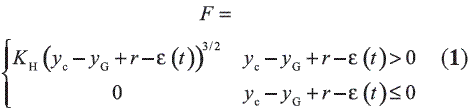
Where yc is the rail vertical displacement, yG is the wheel vertical displacement, r is the radius of the wheel and ε is the wheel profile irregularities.
The research developed by Yan and Fischer [9] have revealed the versatility and feasibility of applying this theory of contact. This investigation includes different relative positions between wheel and rail, with their respective contact areas caused agree to such positions. Through the use of computational resources and the finite element method, numerical calculations were made of the contact pressure distributions, concluding that he theory of Hertz offers performance close to reality, if the contact area is framed within the rail profile.
Wheel-rail contact creepages
According to classical mechanics, the relative motion between two solids is classified in two ways: the first one is based on pure rolling without slipping, while the second refers to the pure slippage in which the force between the tangential two bodies reached the limit of friction, highlighting the fact that below this limit is not slipping. However, there is an intermediate state where the elasticity of body contact, can divide the interaction area in an adhesion area and sliding region, which have a geometry elliptic response to chart in Figure 1 [10]. It is appreciated that the axial axis of the elliptical adhesion zone, coincides with the axial axis of the contact ellipse, and both ellipses coincides at their most extreme point.
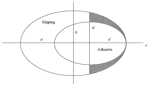
Figure 1 Adhesion and slipping in a elliptical area according to [10]
Below the level of the limiting value of friction there is a finite amount of slip between the two bodies. The magnitude of this slip can be determined by analyzing the elastical and frictional properties of the two bodies. Such slipping below the limiting value of friction is known as creepage which can be calculated from the following velocity relationships showed on Equation 2:
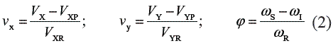
Where VX is the real longitudinal velocity, VXP is the pure longitudinal rolling velocity, VXR is the longitudinal velocity originated by rolling, VY is the real lateral velocity, VYP is the pure lateral rolling velocity, VYR is the lateral velocity derived by rolling, ωs is the angular velocity of the upper body, is the angular velocity of the lower body, and ωR is the nominal rolling velocity.
Theory of Kalker
Kalker proposed a first formulation based on linear relationships between creepage and tangential contact forces [5] according to Equation 3:
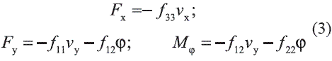
Parameters fij represents creepage coefficients, which depend on rail and wheel shear modulus G, creep coefficients cij, and elliptical contact area dimensions a and b. These parameters and coefficients can be calculated by means of equations 4, 5, 6 and 7, where c33 is a given function of the ratio of the elliptical contact area, whose typical values are tabulated on the literature [6].
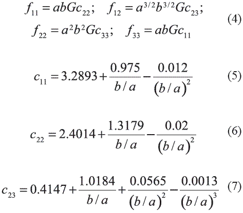
The simplified formulation of Kalker can be used in case of contact closer to nonlinear hertzian contact theory, and interaction bodies with similar characteristics. This simplification takes into account the state of longitudinal, lateral and spin creepages, and considers the wheel and the rail are two rigid solids, whose contact area is modeled by a set of springs located at discrete points on both surfaces. In this way, the displacement zone is represented by a single point of traction which depends only on its surface, causing a status of forces Fx and Fy obtained according to the Equation 8 due to creepages, where s1, s2 and s3 are elasticity contact coefficients defined by Equation 9.
Model of a railway coach on a curved track
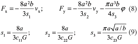
According to the stated in the previous section, when a rail vehicle traveling along a curved track, a dynamic state in the longitudinal and lateral directions due to the wheel-rail interaction is presented. With the aim of study the effects of such state, many investigators have proposed various models of half vehicle [11-13], taking into account that each coach is supported by two bogies containing two axes of wheel individually, and that is symmetric with respect to the vertical axis. Under this context, it has been designed the dynamic rigid model showed in figure 2. This system symbolizes the front of the car and was defined from the assertion that half of the model vehicle is symmetrical with respect the longitudinal axis. Additionally, considering that the behavior of an axis of the bogie is similar to that of the remaining axles that constitute the rail coach, it is assumed that the same is sufficiently characterized by the fourth model vehicle.
Damping and stiffness system characteristics correspond to the bogie suspension and a conventional ballasted track. Mc is the coach mass associated with the weight of the vehicle that hovers over the suspension. In addition to analyzing the vertical translation presented during the movement along straight and curved tracks, it has been included the coach rotation around the longitudinal axis Φc, considering the corresponding moment of inertia. In the same way, the rotation Φw y Φs respect to such axis and referring respectively to the wheel and the sleepers have been taken into account. θc is the rotation of the equivalent vehicle mass around the side axis. The system is described by means four generalized coordinates zc, zw, zr and zs associated with vertical movements of the coach, the wheelset, the rail and the sleepers. Reference level is related with the instant referred to the track with no load, situation in which it is compressed under its own weight.
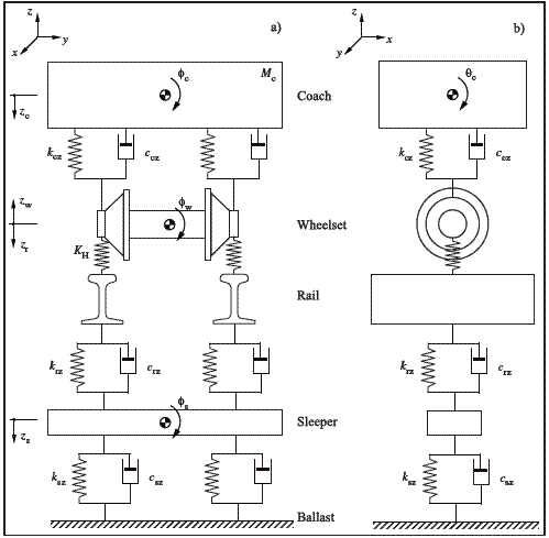
Figure 2 Fourth model vehicle on a curved track. a. Frontal view. b. Side view
Hypothesis of the model
Before defining the equations of motion that describe the dynamics of the proposed system, concrete scenarios and assumptions have been detailed in order to concrete governing fundamentals of the model. These approaches and hypothesis are:
The rail as well as the wheel have similar characteristics and hertzian behavior. Therefore it is possible to estimate the normal contact force and the geometry of the elliptical area of interaction, in an independent form of the longitudinal and lateral forces in the wheel-rail contact area.
The two solid in contact were modeled as a subspace elastic charged on a flat, elliptical and small region; so that it can be possible the identification of local deformations between wheel and rail, presenting a statement of loads within its elastic limit.
The axes of the bogie are located correctly on the curve and the average position of the coach is located on the axis of the track. Therefore, there is no slip of the wheels with the rail and the bogies maintain a constant position on the track, which does not affect the slack side between the axles and the frame of the bogie, and the slack side between the latter and the structure of the vehicle.
The geometric displacement caused by the inscription on the curve of the vehicle is kept constant during movement. Then, the longitudinal and lateral movements of railway equipment are negligible.
The raising of the curve associated with the elevation of the outer rail, is the right and proper to cause a rotation of the different elements of the railway system around the longitudinal axis. Additionally, it is not considered closer tabs of the wheels on the rail, or sideways movement of the coach originated by the action of the centrifugal force.
Being a fourth vehicle model, it does not consider the inclination of the railway vehicle around its center of swinging in the longitudinal direction, besides the transverse forces parallel to the rolling plane are not inclined to the suspension of the bogie’s chassis, hence the rotation around the axis of the coach around the side axis θc is unimportant.
The coach has a balanced distribution of its load, which presents no asymmetry or inclination with respect to the perpendicular of the rolling radius. In addition, due to the high inertia of the railway vehicle, it is possible to disregard the rotation θc around the longitudinal axis.
The instant t = 0 represents the moment at which the coach begins to move through the curved track. Also, the train speed v and the curved track radius R0 are constant.
Equations of motion
Under the assumptions set out and established, the expressions of motion governing the dynamics of the fourth vehicle model have been developed. In the case of the front axle, equations 10, 11 and 12 take into account the problem of normal contact through the nonlinear hertzian theory:
Mw is the wheelset mass, Iwx is the wheelset moment of inertia around the longitudinal axis, kcz y ccz are the stiffness and damping parameters of the suspension, a0 is the half distance between the nominal rolling circles of a wheelset, ds is the half distance between the suspensions of the bogie, dc is the distance between the wheel-rail contact points, FA is the contribution of the coach static load through the left wheel, FB is the contribution of the coach static load through the right wheel, Φw is the rotation of the wheelset around the longitudinal axis, zwL is the vertical displacement of the left wheel, zwR is the vertical displacement of the right wheel, while zw0L and zw0R are the position of equilibrium of the latter two generalized coordinates. Additionally, due to the fourth vehicle model passing through the curved track, the wheels of the same bogie interact with the two rails according to equations 13 and 14:
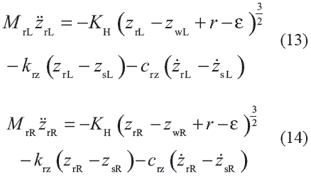
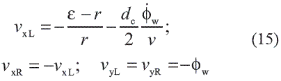
MrL y MrR are respectively the effective mass associated with the left and the right rail, krz y crz are the stiffness and damping parameters of both rails, zrL is the vertical displacement of the left rail, zrR is the vertical displacement of the right rail, zsL is the vertical displacement of the sleeper left side, and zsR is the vertical displacement of the sleeper right side. In order to study the dynamic interaction at the wheel-rail contact area, linear approach of the Kalker theory has been used in the determination of lateral and longitudinal contact forces, considering the normal forces and the creepages calculated according to Equation 15.
These creepages allow to determinate tangential contact forces on the left and right wheels, by means of Equations 16 and 17:
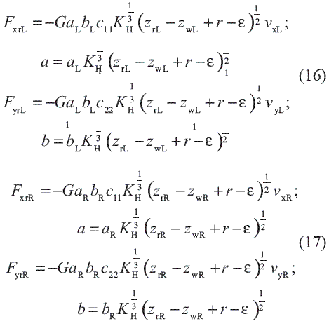
aL and bL are formally defined as the semiaxis elliptical contact area on the left side of the track, related with a normal force equivalent to 1 N. Also, aR and bR describe the geometry of interaction on the right side for the same load conditions. Finally, it should be pointed out the formulations of motion associated with the sleepers and represented by means of Equations 18, 19 and 20:
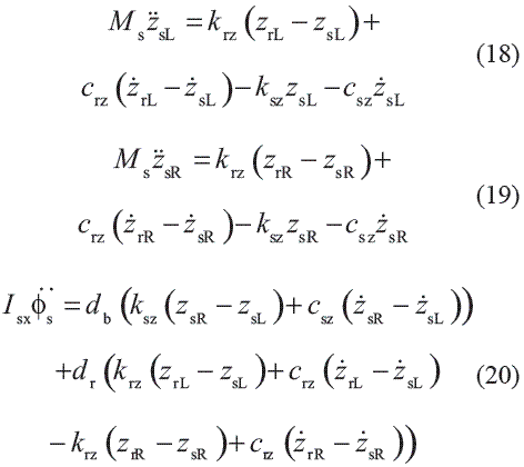
Ms is the mass of the sleeper, Isx is its moment of inertia around the longitudinal axis, ksz y csz are the stiffness and damping parameters between the ballast and the sleeper, and Φs is the sleeper center of inertia rotation around the longitudinal axis. Additionally, as shown in Figure 3, db is the half distance between the sleeper supports on the ballast, dr is the half distance between the rail supports on the sleeper, and bs is the height of the each sleeper.
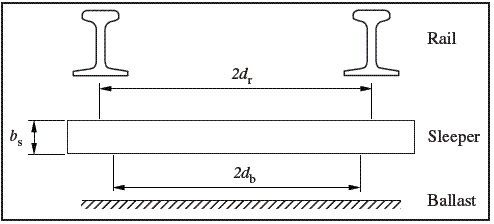
Figure 3 Situation of the supports associated with the sleepers
Results and discussion
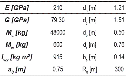
The following discussion refers to a numerical simulation of the described model based on the inclusion of the wheel profile irregularities detailed in figure 4, which has been measured experimentally by means of a linear variable differential transformer [14, 15], and corresponds to a real wheel of a train from the metropolitan network in Barcelona. In addition, the numerical analysis includes the railway system parameters described in table 1.
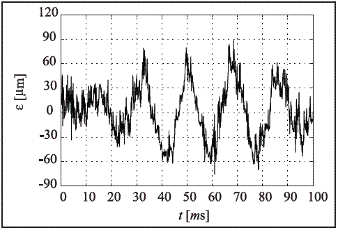
Figure 4 Wheel profile irregularities
Table 1 Railway system parameters
Considering a situation where the coach enters on a curved track oriented to the left, it has been obtained the displacements, the rotation and the dynamic evolution of the railway equipment, by means of the integration of the equations with the fourth order Runge-Kutta method. For example, the graphs presented in figure 5 show that while the coach was moving along a curved track, the displacement in the left wheel is similar to that existing on the right one. Unimportant appreciative variations of the rotation angle of the wheelset, are also observed.
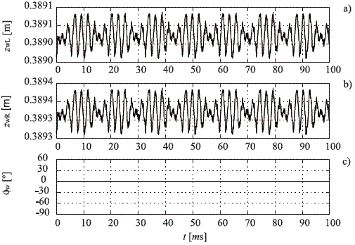
Figure 5 Displacements and rotations related with the wheelset. a. Vertical displacement of the left wheel. b. Vertical displacement of the right wheel. c. Rotation of the wheelset
On the other hand, figures 6 and 7 summarize the vertical displacements and rotations associated with the rails and the sleepers, while figures 8, 9 and 10 present respectively the normal, lateral and longitudinal contact force in both interaction zones.
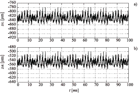
Figure 6 Vertical displacements of the rails. a. Left rail. b. Right rail
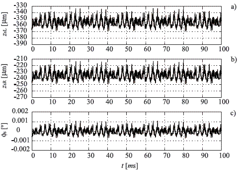
Figure 7 Displacements and rotations related with the sleepers. a. Vertical displacement of the left section. b. Vertical displacement of the right section. c. Rotation of the sleeper
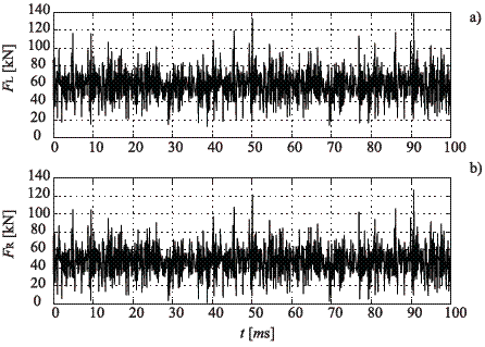
Figure 8 Wheel-rail normal contact force. a. Left side. b. Right side
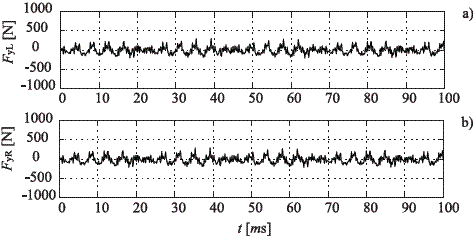
Figure 9 Wheel-rail lateral contact force. a. Left side. b. Right side
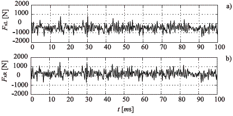
Figure 10 Wheel-rail longitudinal contact force. a. Left side. b. Right side
The numerical simulations have been performed for parameters characterizing the spanish ballasted track. For this average stiffness and damping of the track and the suspension, the most severe system dynamic response was obtained in form of normal contact force. In the train speed studied a maximum force of 138 kN is observed in the left wheel-rail interaction zone. Nevertheless, such force does not produce a very significant vertical displacement on the left rail. In this case, the influence of the excitation represented by means of the wheel profile irregularities is important in the vertical direction of the railway equipment, but does not play a predominant role in the temporary histories of the rotations, as well as the longitudinal and lateral forces.
As shown, there is a good agreement with the dynamic forces calculated during the flange contact that occurs on a curve. From the beginning to the end of the temporary history, several oscillations on the forces are observed, which are around the static load contribution in the case of normal forces, and around no load in the case of lateral and longitudinal forces. These oscillations are a direct result of the excitation in form of wheel profile irregularities, and due to the bogie stable running on both tangent track segments for the forward speed.
The results also show that the dynamic state obtained is analogue in both wheel-rail interaction areas. In the case of study of straight tracks there are no important lateral and longitudinal forces, and the normal problem is equal in both zones. Thereby, in such situation is enough to analyze the generation of normal forces on a single wheel of the train, in order to estimate the dynamic performance derivative of the passage of the wheel. Finally, it must be also pointed out that for the cases studied here, the most important normal contact mainly occurs on the inner wheel of the wheelset. Consequently, when studying the wheel- rail contact forces, the leading wheelset of the coach should always be focused.
Conclusions and final remarks
Through the review for important published papers and investigations on wheel-rail contact, many progresses in this field have been made in the past. These studies are mainly based on numerical procedures and laboratory experiments. Nevertheless, it is very necessary advanced numerical methods in order to predict dynamic interaction efficiently in a short period of time.
In this paper, an analytical model of the railway vehicle interacting with a curved track is presented. Using this model it has been possible to investigate the evolution in the time domain of the contact forces in the wheel-rail interaction zone. The proposed model is characterized by simple equations of motion for the wheelset, the suspension of the bogie, the rails and the sleepers, including the effects of nonlinearities at the contact area by means the hertzian theory, the excitations due to the profile of each wheel and the tangential problem modeled by the theory of Kalker.
The purpose of this investigation was to search about the primary sources of a specific dynamic state due to the passage of a railway vehicle. The most severe system dynamic response, for the real wheel profile studied here, has been the fluctuation amplitude of wheel-rail normal contact force, which is the source of the vertical displacements presented in both rails. In addition, it has been observed that the influence in the lateral and longitudinal directions is not significant.
On the other hand, it is very important to understand the mechanism of the contact force generation in a curved track, in order to study several dynamic phenomena such rail wear, wheel-rail rolling-sliding contact, roughness growth or vibrations generated due to the passage of a train. The present numerical procedure can be further improved in the analysis of these phenomena, and in the optimizing wheel and rail profiles in order to reduce the contact stresses, the generation of vibrations and the wear.
References
1. F. W. Carter. On the action of a locomotive driving wheel. Proceedings of the Royal Society of London. Series A. Vol. 112. 1926. pp. 151-157. [ Links ]
2. K. L. Johnson. The effect of a tangential force upon the rolling motion of an elastic sphere upon a plane. Journal of Applied Mechanics. Vol. 25. 1958. pp. 339- 346. [ Links ]
3. E. Ollerton, R. Pigott. Experimental determination of adhesion and slip areas in rolling contact. The Journal of Strain Analysis for Engineering Design. Vol. 5. 1970. pp. 193-199. [ Links ]
4. F. Al-Bender, K. De Moerlooze. A model of the transient behavior of tractive rolling contacts. Advances in Tribology. 2008. pp. 1-17. [ Links ]
5. J. J. Kalker. On the rolling contact for two elastic bodies in the presence of dry friction. PhD Thesis. Delft University of Technology. Netherlands. 1967. [ Links ]
6. J. J. Kalker. Three dimensional elastic bodies in rolling contact. Ed. Kluwer Academic, Dordrecht, 1990. pp. 50-99. [ Links ]
7. T. X. Wu, D. J. Thompson. A hybrid model for the noise generation due to railway wheel flats. Journal of Sound and Vibration. Vol. 251. 2002. pp. 115-139. [ Links ]
8. J. Otero, J. Martínez, M. A. De los Santos, S. Cardona. Modelo global de la dinámica de contacto rueda-carril para determinar la vibración de un punto del carril al paso de un tren. Scientia et Technica. Vol. 13. 2007. pp. 207-212. [ Links ]
9. W. Yan, F. D. Fischer. Applicability of the Hertz contact theory to rail-wheel contact problems. Archive of Applied Mechanics. Vol. 70. 2000. pp. 255- 268. [ Links ]
10. P. J. Vermeulen, K. L. Johnson. Contact of nonspherical bodies transmitting tangential forces. Journal of Applied Mechanics. Vol. 31. 1964. pp. 338- 340. [ Links ]
11. T. Szolc. Medium frequency dynamic investigation of the railway wheelset-track system using a discretecontinuous model. Archive of Applied Mechanics. Vol. 68. 1998. pp. 30-45. [ Links ]
12. T. Szolc. Simulation of dynamic interaction between the railway bogie and the track in the medium frequency range. Multibody System Dynamics. Vol. 6. 2001. pp. 99-122. [ Links ]
13. X. Jin, Z. Wen, X. Xiao, Z. Zhou. A numerical method for prediction of curved rail wear. Multibody System Dynamics. Vol. 18. 2007. pp. 531-557. [ Links ]
14. S. Cardona, E. Fernández-Díaz. Programa para monitorizar las vibraciones producidas por los trenes de Ferrocarriles Metropolitanos de Barcelona, para estimar el estado general de mantenimiento de los bogies. Convenio FCMB - UPC. 1996. pp. 2-20. [ Links ]
15. E. Fernández-Díaz, Contribución al estudio de la detección y el análisis de las vibraciones producidas por los bogies de un ferrocarril. Tesis Doctoral. Universidad Politécnica de Catalunya. 2000. [ Links ]
(Recibido el 8 de octubre de 2008. Aceptado el 26 de mayo de 2009)
*Autor de correspondencia: teléfono: + 34 + 61 + 888 33 28, correo electrónico: jesus.otero-yugat@upc.edu (J. Otero).

