Services on Demand
Journal
Article
Indicators
-
 Cited by SciELO
 -
 Access statistics
Related links
-
 Cited by Google
 -
 Similars in
SciELO
 -
 Similars in Google
Share
Revista Facultad de Ingeniería Universidad de Antioquia
Print version ISSN 0120-6230On-line version ISSN 2422-2844
Rev.fac.ing.univ. Antioquia no.59 Medellín July/Sept. 2011
Design, modeling, control and implementation of a fuel cell generation system
Diseño, modelado, control e implementación de un sistema de generación basado en una pila de combustible
Carlos Andrés Ramos-Paja*1, Andrés Julián Saavedra-Montes1, Roberto Giral2, Julián David Vega Hincapié1, Ramón Armando Rios Angel1
1Universidad Nacional de Colombia, Carrera 80 N.° 65-223, Medellín, Colombia
2Universitat Rovira i Virgili, Avda. Paísos Catalans 26, 43007 Tarragona, España.
Abstract
This paper proposes analytical expressions to support the design, modeling, control, and implementation of a fuel cell generation system based on power electronics. The system has been designed to ensure safe operating conditions for the fuel cell. The system protection constraints have been obtained by analyzing a detailed fuel cell model. The paper also proposes analytical expressions for designing a DC bus and its regulation system, which have been designed to ensure a voltage deviation between performance limits defined by the application. Finally, the analytical expressions, design procedures and control strategies have been implemented and experimentally validated interacting with the 1.2 kW NEXA Power Module, which is representative of the state of the art in fuel cell prototypes.
Keywords:Fuel cell, DC/DC switching power converter, safe operation conditions.
Resumen
Este artículo propone expresiones analíticas para el diseño, modelado, control e implementación de un sistema de generación basado en una pila de combustible y una interfaz de electrónica de potencia. El sistema fue diseñado para garantizar condiciones seguras de operación de la pila de combustible. Las restricciones de protección del sistema fueron derivadas a partir del análisis de un modelo detallado de la pila de combustible. El artículo también propone expresiones analíticas para el diseño de un bus DC y su sistema de regulación, los cuales fueron diseñados para garantizar una desviación de voltaje dentro de los límites de desempeño definidos por la aplicación. Finalmente, las expresiones analíticas, procedimientos de diseño y estrategias de control fueron implementadas y validadas experimentalmente interactuando con el sistema "1.2 kW NEXA Power Module", el cual es representativo del estado del arte en prototipos de generación basados en pilas de combustible.
Palabras clave: Pila de combustible, convertidor de potencia DC/DC conmutado, condiciones de operación segura.
Introduction
Fuel cells (FC) are efficient electric energy sources that produce minimal pollutant emissions, and therefore are called low emission power sources. Fuel cells transform chemical energy into electrical energy as long as reagents and appropriate conditions are provided [1]. Unlike batteries, in fuel cells the reagents are stored outside the system providing higher autonomy [2]. The main drawback of fuel cells compared with batteries is their low safe bandwidth, which is mainly due to mechanical restrictions in the fuel cell and ancillary devices, thus requiring an additional energy storage device to supply high- frequency electrical loads [3].
Different types of fuel cells use different technologies, electrolytes and/or membranes, being polymer electrolyte membrane (PEM) fuel cells an interesting option due to its high efficiency, low operating temperature, high power density, solid electrolytes, relatively low corrosion and fast start-up compared with other generation systems and fuel cell types [1].
The main fuel cell damage sources are the current ripples and high frequency load transients produced in its operation without any type of control [4]. Those situations generate degradation in the fuel cell membrane and electrodes, it mainly caused by starvation of the reactants required to produce the current requested by the load. Such phenomenon is discussed in the following section.
Those topics have been addressed by using power electronics devices with over-dimensioned input filters, which are commonly designed by considering static electrical characteristics of the fuel cell [5] instead of important dynamics such as oxygen excess ratio [6]. To deal with this topic, analytical expressions for designing a power electronics system to ensure its safe operation are proposed. The constraints in the system design are obtained by analyzing a detailed fuel cell model. Similarly, its control strategy is designed to ensure a safety operation according to the restrictions imposed by the model analysis.
The remains of the paper are organized as follows. The next section describes a dynamic fuel cell model used to define the power electronics constraints. Furthermore, the paper presents the generation system, describing the circuital design and mathematical modeling of the switching DC/DC power converter used to protect the fuel cell, and also the control systems and protection routines involved in the system operation. Finally, the experimental validation of the system by using a benchmark fuel cell prototype is described. Subsequently, the conclusions of the work are given.
Fuel cell model analysis
The fuel cell model used in this paper for the analysis and design is control-oriented and considers experimentally measurable inputs and outputs in order to fit it to the real prototype. The model interacts with the electrical load (DC/DC converter, battery charger, etc.) through electrical equations that model the fuel cell output impedance. The thermal effects on the stack voltage are also taken into account, and the main internal state predicted in the model is the oxygen excess ratio λ02, which is an important variable in FC control and safety [1].
PEM fuel cells consume hydrogen and oxygen to produce electricity; the hydrogen and oxygen flows consumed in such electrochemical reaction for supplying the required stack current (Ist) are given by the following equations (1) and (2), respectively.

where MH2, M0, n, and F are the hydrogen and oxygen molar masses, the number of cells in the stack and the Faraday constant, respectively.
The relation between the oxygen flow provided to the stack and the one required to supply the current demand is normally expressed by the oxygen excess ratio λo2[1] defined in (3).

Here, Wo2,ca,in represents the cathode oxygen flow available in the air flow Wca,in in supplied by the FC compressor, and Wo2,reac represents the oxygen flow consumed in the reaction, which depends on the stack current (2).
High oxygen excess ratio, and thus high oxygen partial pressure, improves the power of the stack; however, after an optimum value is reached, a further increase of its value causes an excessive increase in air compressor losses, thus degrading the system efficiency [2].
The control of the oxygen flow is critical because an oxygen concentration lower than the one required to supply the stack current generates the oxygen starvation effect (OST), which leads to the FC degradation [7]. Therefore, to prevent the OST phenomenon, the oxygen excess ratio must be regulated within λ02 ≥ 1. In [8, 9] the authors propose to track λ02= 2 because this value provides a safe margin against the OST effect.
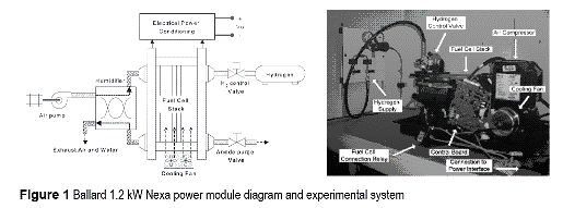
The applied modeling procedure uses experimental data for identifying physical relations and for simplifying complex equations derived from the involved models [3]. The model, then, includes physical and electrochemical equations as well as behavioral relations obtained by interpolating experimental data. The experimental setup used is the Ballard 1.2 kW NEXA Power Module (NEXA), which is composed of a stack of 46 cells with membranes of 110 cm2 surface area. The physical configuration of the fuel cell NEXA module can be seen in figure 1, which shows the interaction between the stack, the air compressor, the humidifier, the cooling system, the hydrogen supply and the anode purge valve.
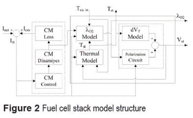
The model inputs are the load current Inet and the ambient temperature Tca,in. Its main outputs are the oxygen excess ratio λO2 and the stack voltage Vst. The stack temperature Tst is calculated in a thermal model used to estimate the voltage deviation caused by stack temperature changes, but it can be also used for prediction purposes.
The thermal model can be obtained by energy balance as described in (4) [10].

The FC-load interaction is modeled by a non-linear relation, where the voltage at the FC terminals dependents on λ02 and Ist. Finally, the stack voltage deviation dVT caused by changes in the stack temperature is also modeled, reproducing in this way the non-linear fuel cell electrical impedance. The model structure is given in figure 2, which shows the compressor dynamics, its losses, and the structure of the control board, where the effective stack current depends on the load current and on the compressor consumption.
The model of the air compressor is based on a Laplace representation of its dynamic behavior, requiring a low computational load and, at the same time, providing a good accuracy. Such transfer function, given in (5), has been identified from the NEXA experimental data,

where Vcp is the compressor control signal (0 % - 100 %) and Wcp is the air mass flow supplied to the FC stack. The compressor control law implemented in the NEXA control board has been experimentally identified as given in (6).

In order to account for the power consumption due to FC system ancillaries, and especially to the air compressor, the stack current Ist must be calculated by the sum of the net current Inet requested by the load and the compressor current Icm. The consumption and losses of the ancillaries have been identified experimentally from the NEXA system as equation (7). Wcp (5), Vcp (6) and Icm (7) identification processes have been performed by following the traditional reactioncurve method.

In the polarization curve modeling by circuital equations, the effects considered are: the activation of both electrodes vA, which corresponds to the voltage contributions of each electrode depend on species and electrode materials; the charge transfer from electrode to electrode vD according to Fick's first law of diffusion [10, 11], related to the carrier concentration; and the voltage drop vR due to the resistive parts of the cell.
The equivalent electric equation that considers these three effects, and therefore describes the same υ(i) characteristic of the cell at any time t, is given in (8),

where ∆E0 is the open circuit voltage, it representing the difference of the standard potentials of the electrodes.
In the case of a stack consisting in the series connection of m cells, some parameters in the equivalent circuit multiplies by m. Finally, the stack impedance model is presented in (9),
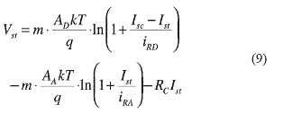
where m = 46 for the NEXA, RC= m·rc stack resistance (rC is a singe cell resistance), AD and AA are parameters experimentally obtained, k is the Boltzmann constant, q the electron charge, and T the stack temperature in Kelvin.
The short-circuit current Isc depends on λ02, and the equation coefficients have been experimentally obtained from polarization curves with λ02 values between 3.0 and 6.5. The identified short- circuit current equation is given in (10).

To consider the effect of the temperature on the stack voltage, the deviation of the polarization curve dVT depending on the changes of the stack temperature from the reference temperature (T0=35°C) has been experimentally identified as (11 ),

where {![]() Tst >To, kdV=0.138} ^ {
Tst >To, kdV=0.138} ^ { ![]() Tst ≤ T0, kdV =0.250}. Finally, from the model equations, it is concluded that fast positive changes in Ist generate fastnegative changes in λ02, and therefore it is necessary to regulate the stack current and air flow compressor to avoid OST. In particular, the stack current and stack power slopes must be in agreement with the maximum air flow slope that ensures a λ02 > 1 condition, which can be obtained from equation (5) and experimental current and power measurements. In the 1.2 kW NEXA power module, the maximum admisible fuel cell power slew-rate is equal to SRfc=250 W/s.
Tst ≤ T0, kdV =0.250}. Finally, from the model equations, it is concluded that fast positive changes in Ist generate fastnegative changes in λ02, and therefore it is necessary to regulate the stack current and air flow compressor to avoid OST. In particular, the stack current and stack power slopes must be in agreement with the maximum air flow slope that ensures a λ02 > 1 condition, which can be obtained from equation (5) and experimental current and power measurements. In the 1.2 kW NEXA power module, the maximum admisible fuel cell power slew-rate is equal to SRfc=250 W/s.
Experimental
Fuel cell generation system
The design of a fuel cell-based power generation system to provide a regulated DC bus with safe fuel cell operation must to consider power conversion circuits and protection systems. The proposed fuel cell generation system considers an unidirectional power flow from the system to the load. In order to design a generic bus supply system, it has been considered a voltage regulated unidirectional DC bus, but it can be easily extended to bidirectional applications for regenerative loads.
In this paper is proposed to regulate the fuel cell current using an input current controlled DC/DC switching converter [6], and an auxiliary storage device is required for transients supply. In this aspect, the interaction of supercapacitors and fuel cells has been analyzed in [12, 13], whose results are also valid for high capacitive-low resistance capacitor banks.
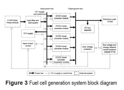
The block diagram of the proposed fuel cell generation system is depicted in figure 3. It considers a DC/DC power converter and an input filter in series with the fuel cell NEXA module, which regulates a capacitive DC bus to supply the load. Also, there are considered the power converter input current control and bus overvoltage protection.
The NEXA user manual [14] reports maximum operating limits for stack voltage of 22 V at short current transients (60 A - 70 A for 10 ms - 1 ms, respectively) and 50 V for null stack current. In this paper it is considered a real, and experimentally measured, safe stack voltage range between 26 V and 46 V. Also, considering the common use of 48 V (or above) DC buses (telecom, aerospace, electric vehicle, etc.), a boost DC/DC switching converter topology has been selected. In addition, the boost topology has the inductor in series with the power supply, allowing in this way to constrain the input current ripple, which is not possible in buck converters due to its discontinuous input current, requiring therefore a high input filter for this issue. The designed switching converter has a nominal power of 1.2 kW to support the NEXA requirements, but in order to make it robust, redundant and scalable, it was developed using four power conversion modules, each one of them with a maximum power of 300 W. The converter structure is also flexible to support lower or higher power systems using different number of modules. This is showed in figure 3, where input and output power buses allow the connection of multiple power conversion modules.
Considering the negative impact of high frequency components of the current-ripple into the FC health [4], this scheme allows to reduce those current components by shifting the phase of inductor current waveforms. Such procedure generates that parallel modules exhibit opposite current slopes for fractions of the switching period producing a partial cancellation between the corresponding current ripples.
DC/DC boost converter modules design
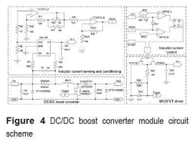
The circuit scheme of each DC/DC boost converter module is depicted in figure 4, where it is observed the boost converter, inductor current sensing and conditioning, inductor current control, and MOSFET driving circuit. The core of the converter module is the DC/DC boost converter, whose basic elements are the inductor L, MOSFET N-channel and SCHOTTKY diode, and also a Rsense shunt resistor was introduced to measure the inductor current.
This switching converter can operate in two modes [15, 16]: Continuous Conduction Mode (CCM), when the inductor current exhibits a continuous waveform; and Discontinuous Conduction Mode (DCM), when the inductor current exhibits a discontinuous waveform. In this implementation, the converters operate in CCM, and each module supports up to 300 W and its inductor was designed for a nominal current of 10 A.
Inductor design
Since the inductor current waveform is triangular, the equation (12) is used to select the in ductor value L to obtain a desired ∆iL value [16],

where Vg is the DC input voltage, V is the DC output voltage, f is the switching frequency, and D is the duty cycle given by D=(V-Vg)/V for this boost topology. The parameters considered in this design are Vg=34 V, V=48 V, f=50 KHz, ∆iL=3.5 A and D=0.2917. The calculated inductor value was L=56 µH, and the values measured using a QUADTECH LCR 1910 inductance analyzer [17], at the nominal conditions, are: L=56 µH, RDC=12 mΩ, ESR20kHz=145 mΩ, ESR50kHz=175 mΩ and ESR100kHz=300 mΩ .
Input and output capacitors, and protection diodes
Since the output capacitor voltage waveform is triangular, equation (13) is used to select the capacitance C to obtain a given output voltage ripple magnitude ∆v [16].

In equation (13), RL is the nominal load calculated by RL=V/Iout=6.85 Ω. Iout=Vg ·Inom/V=7 A is the maximum output current, Inom =10 A is the converter nominal current, and ∆v=0.5 V is the desired voltage ripple. From those parameters a 41 µF output capacitor was calculated, where the selected commercial value was C = 44 µF. The same value is used for the input capacitor. Additionally, the capacitors were localized near to the inductor and diode, and the selected capacitor technology was EPCOS MKT (100 V, 10 % tolerance), both to reduce the electromagnetic radiation generated by the converter. Also, an anti-parallel STTH12R06D diode was introduced to allow the inductor discharge and to avoid negative capacitor voltages. Another anti-parallel diode was introduced in the converter output to avoid negative voltage conditions in the capacitive bus, i.e. in suddenly disconnection of inductive loads.
In addition, the series resistance of a MKT technology capacitor can be calculated from (14),

where Q is the quality factor, which for MKT capacitors is Q=160. For the nominal operating frequencies: ESR20kHz=17.28 mΩ, ESR50kHz=43.19 mΩ and ESR100kHz=86.39 mΩ.
DC bus capacitor design and voltage regulation
A capacitive storage was selected to supply power transients due to its high-frequency capabilities, easy state of charge (SOC) estimation and low serial resistance in contrast to battery-based systems. In order to provide a regulated DC bus, the bus capacitor dimensioning and energy regulation must ensure a system behavior into admissible voltage limits and power transients restoring times. In the power interface, the relations between the switching converter, capacitor bus and load currents and powers are given by (15),

where idc/dc and Pdc/dc correspond to the output of the switching converter, icb and Pcb to the bus capacitor, and iLoad and PLoad to the load. Also, it is necessary to take into account the switching converter losses, which are represented by a power conversion efficiency ηdc/dc considered constant in all the power range.
In a power transient, the bus capacitor initially supplies the power to the load, and then the fuel cell operating point is moved to the new steady state constraining its maximum power slope to the defined slew-rate limit. If the load current has a high-frequency ripple, this one is supplied by the bus capacitor and the fuel cell provides the low-frequency components.
In order to dimensioning the bus capacitor, the following DC bus parameters were defined: maximum load power transient considered ∆PL [W], maximum admissible fuel cell power slew- rate SRfc [W/s], and maximum acceptable bus voltage deviation Kvb (%). Due to the power converter efficiency, the effective slew-rate limit that affects the power delivered to the capacitor and load is SR = ηdc/dc · SRfc [W/s].
The most critical load transient case is reached in a power step of ∆PL, in which the fuel cell power will be changed with a slope SRfc until it reaches the new steady-state power point at ∆td=∆PL/SR [s]. Therefore, the power Pcb(t) supplied by the capacitor in this time interval can be expressed as (16),

and the energy ETcb exchanged between the bus capacitor and the load is given by (17).

Also, this energy difference produces a bus voltage variation of (Kvb/100)·V0bus from its steady-state value V0bus. This voltage change can also be expressed as a function of the capacitor initial and final energies, when the power exchange with the load has ended, as (18).

Finally, from (16), (17), and (18) can be calculated the capacitance that ensures the maximum bus voltage change and restoring time desired, at the given load transient, as (19).

Considering the parameters of the experimental system ηdc/dc = 85 %, Vobus = 48 V, Kvb=5 %, ∆PL = 300 W and SRfc= 250 W/s, the required bus capacitance is Ccb= 1.9 F.
The power conditioning input current must be controlled to regulate the fuel cell stack current, and therefore the converter modules are controlled in current mode. In this way, the inductor current was controlled by using the sliding mode control technique [18], which provides a fast transient response with a small overshoot, and guarantees a very low sensitivity to external perturbations.
DC/DC Boost converter modules modeling and control
The scheme of the selected DC/DC boost converter can be observed in figure 4. By applying the average modeling technique, the bilinear system [16] given in (20) is obtained,

where u represents the state of the MOSFET (u = 1 for ON, u = 0 for OFF) and diode (u). For the converters sliding mode control [18], the desired sliding surface is described by (21),

where IBRef represents the average inductor current reference imposed to the boost converter, being it considered constant in the cycle and in the middle of the hysteresis band of the comparator [19]: IBRef = (IMAX+IMIN)/2, where IMAX and IMIN correspond to the maximum and minimum admissible current values, respectively.
To ensure a sliding trajectory around S(x), and therefore to achieve the control objective, it is necessary to satisfy the conditions given by (22) and (23).


From (22), S(x)=0=IL-IBRef, therefore IL=IBRef, i.e. the control objective. Also, from (23), it is derived  . From this equation, and using the sliding mode equivalent control technique for switching converters [18], equation (24) is obtained,

where ueq represents the percentage of switching period when the MOSFET is ON. The conditions to ensure the equivalent control are: 0 < ueq < 1↔1> 1-ueq > 0, which being applied to (24) leads to:

Inequality (25) constrains the derivative of the reference between the inductor current charge and discharge slopes, which define the conditions for existence of the sliding-mode.
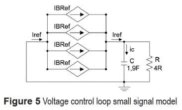
Considering the modules current control, the closed loop modules can be modeled by ideal current sources, and therefore the voltage control system can be expressed as given in figure 5. The equations that describe the voltage dynamics are: ic=Iref - Vc /R =C dvc /dt and Iref = Pref /vc , which leads to dvc /dt = Pref /vcC - v c/RC.
Defining the new state vector x = [v ], the voltage dynamics can be expressed by x=Ax+Bw, where  and w = [Pref]. In the nominal operating point, where the system is linearized, the steady state values are vc=48 V and Pref =530 W.
The bus voltage model depending on the overall input current is given by (26),

and the controller designed to ensure a damping factor ξ=0.707 and a settling time ts=2.7s is given by (27), which provides an infinite gain margin and a phase margin PM=66.9.

Results and discussion
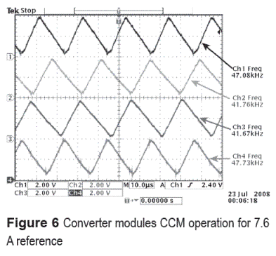
In the implementation of the current controllers, a window comparator was used to detect when the current reaches its maximum and minimum allowed values, where it triggers the RESET or SET signals of a S-R flip-flop, respectively, as depicted in figure 4. This flip-flop reduces the circuit noise sensibility and it stores the switching state applied to the MOSFET driver. Figure 6 shows the experimental inductor currents of the four converter modules operating in CCM, where each module is controlled by its own local current control which reference IBRef is defined to obtain the desired average input current IRef.
The inductor currents in the converter modules exhibit triangular waveforms, but due to the small differences in the inductors, capacitors, diodes and MOSFET drivers, the triggering times are not equal, causing in this way partial current ripple cancelation [20] as depicted in figure 6. The experimental switching frequencies of the sliding-mode converters are between 40 kHz and 50 kHz.
The amount of canceled ripple depends on the inductor currents phase differences, which depend on the electric elements discrepancies. In this way, the four-module power system gives a natural partial input current ripple cancelation.
Input filter
To reduce the high frequency components injected to the fuel cell, an input filter was designed to absorb the remaining current ripple not cancelled by the parallel operation of the converter modules, which in normal operating mode, is constrained to [0 A, 14 A]. The probability of experimenting the 14 A worst case, four modules in perfect phase, is minimum due to the electric elements differences, but for fuel cell safety it has been considered. The input filter consists in the L-C network (Lf, Cf1) observed in figure 7, which cut-off frequency is given by (28), and in the implementation is equal to Fco=3.5 kHZ.

This frequency is a decade under the minimum switching frequency, being it enough to remove the high frequency components from the fuel cell current. If a higher load power is required, the current capacity of the filter must be increased, but keeping the same cut-off frequency, and therefore the same inductance and capacitance values.
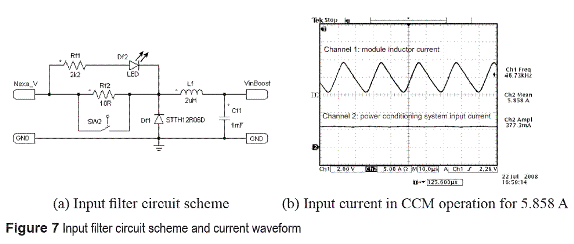
The circuit scheme of the implemented input filter, depicted in figure 7(a), has an additional network Rf2-SW2 used to charge the capacitive bus and input filter with a constrained current slope to respect the fuel cell dynamics, and to avoiding damages in the start-up of the system.
The power conditioning experimental current, and therefore fuel cell current, is depicted in figure 7(b). The measured input current ripple is approximately 377.3 mA, being this ripple almost constant due to the low variation of the hysteresis band.
Such current ripple is acceptable because it represents less than 10 % of the nominal fuel cell current [21], being a 0.82 % in this experiment. Also, in the experiment presented in figure 7(b), the current ripple corresponds to 6.4 % of the DC current, it being under the maximum recommended 30 % limit for high and low frequency current ripples in fuel cells [14, 22]. Finally, figure 7(b) also shows the current of one phase to illustrate the switching frequency.
Control board and overvoltage protection
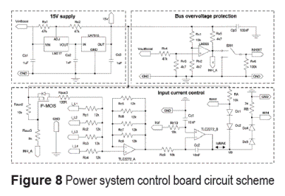
The supervisory controller of the converter modules includes the average input current control and overvoltage protection, which ones must be applied to all the modules at any time. Those control strategies were implemented in a single control board described in figure 8.
The control board includes a 15 V voltage source, which allows supplying the ancillary devices using the fuel cell power without additionally supplies.
The average input current regulation strategy was implemented using a voltage average operational amplifier, which calculates the average input current value from the inductor current sensing signals of the converter modules. Next, the error of the average current from the reference Iref is processed by an integrator operational amplifier that closes the control loop. The resulting control signal defines the average current reference for the sliding mode current controllers, where the relation between RA and RB resistances in the scheme of figure 8 defines the maximum and minimum values of the hysteresis band.
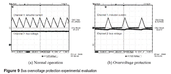
The control board also implements the bus overvoltage protection, which consists in a comparator network that evaluates the bus voltage in front to a preset maximum allowed voltage of 55 V. The comparator generates an INHIBIT signal that forces the MOSFET shutdown in the converter modules, reactivating the MOSFET switching control when the overvoltage condition is over. An additional P-MOS MOSFET and resistors network has been introduced to minimize the current peaks in converter MOSFET reactivation, which is activated by the comparator output, INH_A in figure 8, forcing the fast drop to zero of the integrator output. This condition disappears when the overvoltage condition ended because the P-MOS is inhibited and the integrator recover its control inputs. This generates a burst mode (BM) [23] behavior of the converter, where the converter absorbs in DCM the required average power in each cycle without incrementing the switching frequency in small current conditions. BM is used because to limit the output voltage, and therefore to prevent the destruction of the bus capacitor, it is required to reduce the converters current.
The experimental evaluation of the overvoltage protection is depicted in figure 9, where figure 9(a) experiment shows a normal operation with the bus voltage under the restriction of 55 V, being 47.9 V in this case. Figure 9(b) presents the effect of the protection when the bus voltage arrives the 55 V limit, reporting a satisfactory behavior. It is observed the BM caused by the overvoltage protection, which generates a DCM inductor current.
Transient response of the fuel cell generation system
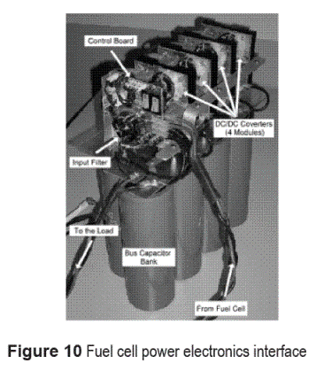
The experimental fuel cell power electronics interface is depicted in figure 10, where it is observed the 1.9 F bus capacitor bank, the four controlled DC/DC converter modules, the control board, and the input filter.
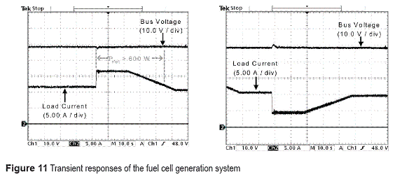
Finally, the experimental behavior of the developed power electronics system interacting with the 1.2 kW Nexa power system is presented in figure 11, where the load current exhibits high and low frequency transients that are compensated by the voltage controller, regulating in this way the bus voltage in the desired performance, where the maximum allowed deviation Kvb = 5% from desired bus voltage V0bus = 48 V is achieved. The maximum time interval when the bus voltage is deviated from V0bus inside Kvb band is calculated from the capacitor differential equation to 5.4 s for a load transient equal to 300 W. A first high power step-up transient (Pnet > 600 W) generates a small voltage reduction that is satisfactorily compensated by the voltage regulator. Similarly, a second step-down transient is applied, and the power electronics systems behave properly for the bus regulation. In both cases the fuel cell current slope is constrained to avoid damages, and the restoring time fulfills the performance criterion, and in particular in the higher load transient of 289.6 W such time is 3.4 s, being therefore satisfactory. Additionally, the slow slew-rate power transients (12 W/s) are rejected, which allows achieving a negligible deviation from the nominal DC bus voltage.
Conclusions
This paper proposes analytical expressions to design power electronics systems intended to safely supply electronic loads using fuel cells. Experimental results show the satisfactory regulation of the load bus with safe fuel cell operation, validating the analytical expressions.
The proposed approach consisting of an array of four DC-DC converters in parallel to reduce the current ripple in contrast to traditional singlestage converters, which has been evidenced in the comparison of a single module and the overall system current waveforms. This system is regulated to constrain the slope of the fuel cell current into security limits. Additional filter design has been discussed to provide an extra margin on the safety conditions.
With the objective of supplying electronic loads, it has been provided analytical expressions to DC bus design according to performance specifications. Besides, control structures were designed to regulate both the converter and the DC bus. Additional overvoltage protection was designed to avoid damages on the DC bus, load and converters. Experimental results show the correct operation of protection systems in presence of load transients, validating the power structure.
Finally, the use of advanced techniques for switching converters design and control, such as interleaving, would optimize the cancellation of current ripples to reduce significantly the size of the input filter, which allows a future improvement of the proposed system.
Acknowledgments
This work was supported by GAUNAL and GITA research groups of the Universidad Nacional de Colombia, and the GIT group of the Instituto Tecnológico Metropolitano under the projects DACOGEN-PV and MECOVA-WIND, by Universitat Rovira i Virgil, by the Spanish Ministerio de Ciencia e Innovación under the project TEC2009-13172, and by the Colombian Departamento Administrativo de Ciencia, Tecnología e Innovación (COLCIENCIAS) under the scholarship 095-2005.
References
1. J. T. Pukrushpan, A. G. Stefanopoulou, P. Huei. "Control of fuel cell breathing". Control Systems Magazine IEEE. Vol. 24. 2004. pp. 30-46. [ Links ]
2. J. T. Pukrushpan, A. G. Stefanopoulou, H. Peng. Control of fuel cell power systems: principles, modeling, analysis, and feedback design. Ed. Springer Verlag. London. 2004. pp. 1-61. [ Links ]
3. A. J. del Real, A. Arce, C. Bordons. "Development and experimental validation of a PEM fuel cell dynamic model". Journal of Power Sources. Vol. 173. 2007. pp. 310-324. [ Links ]
4. R. S. Gemmen. "Analysis for the effect of inverter ripple current on fuel cell operating condition". Journal of Fluids Engineering. Vol. 125. 2003. pp. 576-585. [ Links ]
5. D. D. Marquezini, D. B. Ramos, R. Q. Machado, F. A. Farret. "Interaction between proton exchange membrane fuel cells and power converters for AC integration". IET Renewable Power Generation. Vol. 2. 2008. pp. 151-161. [ Links ]
6. C. A. Ramos, A. Romero, R. Giral, L. Martinez Salamero. "Maximum Power Point Tracking Strategy for Fuel Cell Power Systems". IEEE International Symposium on Industrial Electronics. 2007. pp. 2613-2618. [ Links ]
7. C. Bordons, A. Arce, A. J. del Real. "Constrained predictive control strategies for PEM fuel cells". American Control Conference. 2006. pp. 2486-2491. [ Links ]
8. A. Vahidi, A. Stefanopoulou, P. Huei. "Current Management in a Hybrid Fuel Cell Power System: A Model-Predictive Control Approach". IEEE Transactions on Control Systems Technology. Vol. 14. 2006. pp. 1047-1057. [ Links ]
9. S. Kyung-Won, A. G. Stefanopoulou. "Performance Limitations of Air Flow Control in Power-Autonomous Fuel Cell Systems". IEEE Transactions on Control Systems Technology. Vol. 15. 2007. pp. 465-473. [ Links ]
10. C. Ramos Paja, R. Giral, L. Martinez Salamero, J. Romano, A. Romero, G. Spagnuolo. "A PEM Fuel Cell Model Featuring Oxygen Excess Ratio Estimation and Power Electronics Interaction". IEEE Transactions on Industrial Electronics. Vol. 57. 2010. pp. 1914-1924. [ Links ]
11. G. Wang, M. Lee, W. Chen, Y. Chen, M. Chien, M. Yu. "A Metal-Solution Field-Effect-Transistor Enhanced Proton-Motive-Force Driving Photovoltaic". IEEE Transactions on Nanotechnology. Vol. 2. 2011. pp. 191-196. [ Links ]
12. J. Moreno, M. E. Ortuzar, J. W. Dixon. "Energy- management system for a hybrid electric vehicle, using ultracapacitors and neural networks". IEEE Transactions on Industrial Electronics. Vol. 53. 2006. pp. 614-623. [ Links ]
13. M. Ortuzar, J. Moreno, J. Dixon. "Ultracapacitor- Based Auxiliary Energy System for an Electric Vehicle: Implementation and Evaluation". IEEE Transactions on Industrial Electronics. Vol. 54. 2007. pp. 2147-2156. [ Links ]
14. Ballard Power Systems Inc. Ballard Nexa Power Module Users manual. Ballard Power Systems Inc. Vancouver. 2006. pp. 90-100. [ Links ]
15. B. W. Williams. "Basic DC-to-DC Converters". IEEE Transactions on Power Electronics. Vol. 23. 2008. pp. 387-401. [ Links ]
16. R. W. Erickson, D. Maksimovic. Fundamentals of power electronics. Ed. Kluwer Academic Pub. Boston (MA). 2001. pp.107-126. [ Links ]
17. Quadtech Inc. Web page available at http://www.quadtech.com/. Accessed 5 July 2008. [ Links ]
18. R. Giral, L. Martinez Salamero, R. Leyva, J. Maixe. "Sliding-mode control of interleaved boost converters". IEEE Transactions on Circuits and Systems I: Fundamental Theory and Applications. Vol. 47. 2000. pp. 1330-1339. [ Links ]
19. M. Lopez, L. G. de Vicuna, M. Castilla, P. Gaya, O. Lopez. "Current distribution control design for paralleled DC/DC converters using sliding-mode control". IEEE Transactions on Industrial Electronics. Vol. 51. 2004. pp. 419-428. [ Links ]
20. D. J. Perreault, J. G. Kassakian. "Distributed interleaving of paralleled power converters". IEEE Transactions on Circuits and Systems I: Fundamental Theory and Applications. Vol. 44. 1997. pp. 728-734. [ Links ]
21. Y. R. de Novaes, R. R. Zapelini, I. Barbi. "Design Considerations of a Long-Term Single-Phase Uninterruptible Power Supply Based on Fuel Cells". IEEE 36th Power Electronics Specialists Conference. 2005. pp. 1628-1634. [ Links ]
22. C. Huang-Jen, Y. Chun-Jen, L. Yu-Kang. "A DC/ DC converter topology for renewable energy systems". International journal of circuit theory and applications. Vol. 37. 2009. pp. 485-495. [ Links ]
23. M. Budaes, L. Goras, "Burst mode switching mechanism for an inductorless dc-dc converter". International Semiconductor Conference. 2007. pp. 463-466. [ Links ]
(Recibido el 8 de marzo de 2010. Aceptado el 10 de marzo de 2011)
*Autor de correspondencia: teléfono: + 57 + 4 + 425 53 45, fax: + 57 + 4 + 234 10 02, correo electrónico: caramosp@unal.edu.co (C. Ramos)


