Serviços Personalizados
Journal
Artigo
Indicadores
-
 Citado por SciELO
 -
 Acessos
Links relacionados
-
 Citado por Google
 -
 Similares em
SciELO
 -
 Similares em Google
Compartilhar
Revista Facultad de Ingeniería Universidad de Antioquia
versão impressa ISSN 0120-6230versão On-line ISSN 2422-2844
Rev.fac.ing.univ. Antioquia n.59 Medellín jul./set. 2011
Decoupled control for internal combustion engines research test beds
Control desacoplado para bancos de ensayo para investigación en motores de combustión interna
José David López1, Jairo José Espinosa1, John Agudelo2*
1Automation and control group (GAUNAL), Mechatronics School, Faculty of Mines. Universidad Nacional de Colombia in Medellín
2Facultad de Ingeniería, Universidad de Antioquia. Calle 67 N.° 53-108. Medellín (Colombia)
Abstract
This article presents a solid and robust automation model which has been developed and implemented in two different research engine test beds which were instrumented, one for diesel and the other one for spark ignition engines. The model, programmed in Matlab, is based on transfer functions with a decoupled (two single input single output systems) independent proportional and integral action controller that allows setting the desired engine speed and torque under stationary operation conditions. It was implemented in a Freescale HC08 family microcontroller external to the PC in order to avoid the risk of losing control during undesirable communication delays on the computer.
The model has been validated in a wide range of engine operating modes, from low to high speeds and loads showing a good response. The first order transfer functions with delay have proven to be a good approximation even during the nonlinearities caused by turbocharger and electronic control unit incorporated in the engines. This low cost automation system has been tested for the last three years in a university engine laboratory showing a good performance.
Keywords:Engine test bed, automation, transfer function, decoupled controller.
Resumen
En este artículo se presenta un modelo de automatización sólido y robusto, que ha sido desarrollado e implementado en bancos de ensayo debidamente instrumentados, usados para investigación tanto en motores diesel como de encendido por chispa. El modelo, programado en Matlab, está basado en funciones de transferencia con un controlador proporcional e integral desacoplado (dos sistemas de una entrada y una salida) que permite fijar las condiciones de operación estacionarias de régimen y par motor deseadas. El modelo se implementó en un microcontrolador de la familia Freescale HC08 externo al computador, con el objeto de evitar el riesgo de pérdida del control por eventuales retardos en la comunicación con el computador.
El modelo ha sido validado en un amplio rango de modos de operación que van desde bajas hasta elevadas velocidades y cargas mostrando una respuesta apropiada. El uso de funciones de transferencia de primer orden con retardo probó ser una buena aproximación aún en presencia de las no linealidades generadas por el turbocompresor y la unidad de control electrónica de los motores. Este sistema de automatización de bajo costo ha sido probado durante los últimos tres años en un laboratorio de motores universitario mostrando excelente desempeño.
Palabras clave: Banco de ensayo de motores, automatización, funciones de transferencia, control desacoplado.
Introduction
Investigation and development tasks in internal combustion engines (ICE) requires precise and reliable control systems in order to avoid false conclusions, especially when small differences are expected. This is the case when several fuels, blends of fuels, additives, fuel saving devices or postreatment systems (among others) will be compared in an engine test bed. An internal combustion engine is a machine that involves thermodynamic processes, fluid mechanics and chemical reactions and modeling is still subject of discussion [1]. Several authors agree that the dynamic of the combustion chamber is the dominant process of the ICE [2-5], which implies the use of different models according to the engine ignition system (compression or spark). This prevents the use of a generic control model design. On the eddy currents dynamometer the coil inductance is the result of its geometry and material characteristics [6-8]. In absence of manufacturer information, it is possible to retrieve the parameters from experimental data, in order to obtain a proper model since torque is directly proportional to current flowing through the brake and shaft speed as well [9].
The inherent difficult of modeling engine-brake assembly using phenomenological models applied to control systems, such as the mentioned above, has forced some authors to take into account a reduced number of variables. Hopkins and Morris [10, 11] developed models with seven state variables with numerous parameters, later Powers [4] reduced to five state variables and stated that for a digital control, a relatively low order model (quasi-linear and discrete-time) was adequate, due to the restrictions in control implementation, i.e. an approach of transfer functions can be successful in the vicinity of a speed-torque point. Bunker et al. [1] and Cook et al. [12] have followed this approach and have designed models of two inputs and two outputs with transfer functions of first and second order with delay applied to speed and torque control systems.
In this work a decoupled proportional integral control system for engine speed and torque has been developed, it was based on first order transfer functions with delay and it has been successfully implemented and validated in the whole range of operation of a diesel and a spark ignition engine- dynamometer assembly systems. This novel approach is different from those used by Cook et al. [12] and Bunker et al. [1], since the formers included in their model the spark ignition process as a fast dynamic in order to respond to transients in braking torque, so this model could not be used in diesel engines or without private information of the spark system. Bunker et al. [1] used a second order model in the interdependent loops, which was implemented, only on the lineal region of a spark ignition engine, avoiding nonlinearities. The instrumentation and automation of both test bench for ICE were developed and implemented by the authors. Results have proven to be similar in performance to commercial test bench facilities but the financial cost has been reduced more than twenty times.
Methodology
Equipment and systems
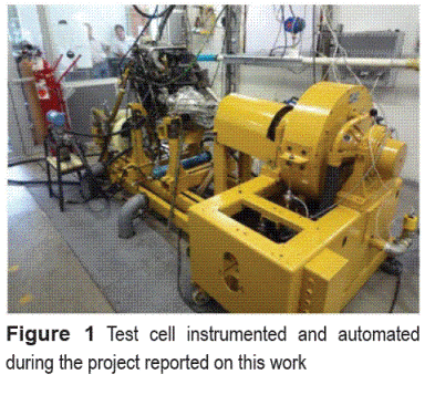
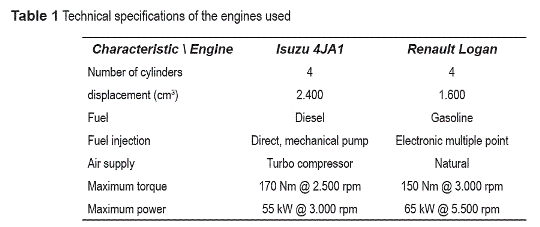
Two engine test beds were instrumented and automated; one was used to research in diesel engines and the other in spark ignition engines. Figure 1 shows one of the two instrumented and automated cells and table 1 presents the technical specification of the engines used in this work. The diesel engine was coupled to a Schenck W230 eddy current dynamometer, while the spark ignition engine was coupled to a Schenck E90 eddy current dynamometer. Both test beds have been instrumented with hot-wire air flow sensors (Magnetrol TA2), K-type thermocouples (ambient temperature, inlet-outlet engine water, oil, hot gases, turbocompressor inlet and outlet temperatures) and strain gage pressure transducer sensors (ambient pressure, turbocompressor inlet and outlet and oil pressures). The diesel fuel flow was measured with an electronic balance, while the gasoline was measured with a Danfoss Masflo 6000 Coriolis-type mass flow sensor.The engine speed sensors were mounted in the electromagnetic brakes. The Schenck E90 brake had an optical sensor, while the Schenck W230 had a magnetic reluctance sensor. A frequency- voltage converter based on the LM2907 integrated circuit was implemented.
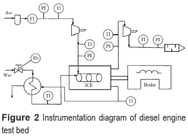
The engine torque was measured with load cells attached to the brake stators. This signal reached few milliamps and it was very sensitive to noise, to solve these problems, a common mode rejection ratio amplifier (CMRR) was implemented. It neglects the noise that enters through the casing and amplifies the signal between 1000 and 5000 times. A low-pass active filter with a cutoff frequency below the minimum engine speed (idle) was implemented in order to avoid undesirable variations provoked by piston movement. Figure 2 schematically shows the diesel engine test bed. In order to obtain detailed thermodynamic information from the engines operating with several renewable and conventional fuels, an in-cylinder piezoelectric pressure transducer (Kistler 6056A) was mounted in cylinder No. 1. The instantaneous signal was converted into voltage with a Kistler 5011B charge amplifier. The instantaneous piston position was determined using an angular encoder with a resolution of 1024 pulses/revolution (Heidennhain ROD 426) coupled to the crankshaft at the opposite extreme of the fly-wheel.
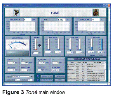
High speed data were acquired using a LabView™ based software with a National Instruments™ data acquisition system (Model PCI-MIO-16E-4 board). The program developed by the authors for real time monitoring and recordering was called Tone (Figure 3). The engine speed system is controlled by the fuel entering the combustion chambers which is strongly governed by the throttle valve position of the acceleration system. The engine speed and torque depend on the fuel entering the engine and on the electric current supplied to the dynamometer, i.e. both variables are interrelated and a change in any of them has a significant effect on the other.
To control the acceleration (degree of throttle valve opening) a direct current stepper motor with an incorporated gearbox was used. A direct current flowing through the brakes coil, similar to those used to control the speed in DC motors was used to generate brake resistance (load). In order to guarantee the appropriate operation mode, it was developed an 80V-20A source with a chopper based on MOSFET transistor, controlled by a pulse width modulation (PWM) at a frequency of 5 kHz.
Automation model description
Multiple inputs and multiple outputs (MIMO) transfer functions model
A test bench for alternative fuel analysis must use commercial vehicle engines without modifications, and the main comparison parameter is the power on different set points of speed and torque. These requirements only allow using the throttle and the brake load as actuators (considering that gasoline commercial vehicle engines do not allow to modify the spark control).Based on the considerations proposed by Powers [4] and the successful works developed by Bunker et al. [1] and Cook et al. [10], the internal combustion engines used in this project were modeled with independent transfer functions [13-15] according to the matrix of eq. (1), where only both actuators and control variables were related reducing the number of parameters that must be calculated:
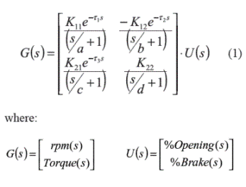
rpm(s):
Engine speed in rpm
Torque(s):
Brake torque in Nm
%Opening(s):
Percentage of throttle opening
%Brake(s):
Electric current entering the brake represented in divisions of PWM
Kij:
Gains
τi:
Delay in seconds
1/a,1/b,1/c,1/d are the time constants of the subsystems.
System inputs are the percentage of throttle opening and current through the dynamometer, and the outputs are the engine speed and torque. After several tests the authors found that the nonlinearities become manifest on gain changes, and less significant changes on pole locations and delays. Because of this the authors implemented this first order transfer functions model.
To find the parameters of the matrix of transfer functions, the following procedure was implemented, covering a wide range of engine operating modes:
A test of acceleration steps (each 5%) without any brake load was carried out from idle to maximum engine speed. With the throttle valve fixed in the maximum engine speed point, current steps (each 5%) were applied on the dynamometer coil, increasing load until engine speed reached the minimum. Alternating the acceleration and load, steps 1 and 2 were carried out until the engine reached its maximum power in order to obtain relevant data from the majority operating modes. The zero load test was detected as the region with higher instabilities because the engine had greater gain with low load. When load was increased the gain was reduced making the system more stable.
The IDENT toolbox of Matlab® was used after obtaining these experimental data in order to find the parameters of each curve, the models were adjusted using sequential quadratic programming, and reducing the mean prediction error with respect to a persistent excitation experiment on the plant. For a better performance, the datasets were normalized before entering the program. 100 curves were acquired and 70 were used on identification, approximately eight curves for each engine located throughout the operating range (speed and torque) were used in order to obtain each subsystem model. All sub-models were validated in operating modes different from those used in the procedure described above.
The first-order models with delay obtained for the engines were:

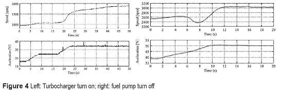
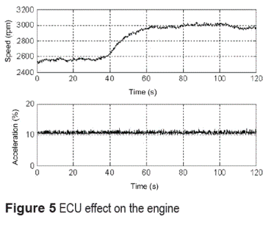
Turbocharger turn-on and fuel pump turn-off were the most significant nonlinearities of the diesel engine. The first is provoked by engine fluid dynamics causing a sudden increase of engine speed, while the second is provoked by the turbocharger turn on and the fuel pump turn engine-fuel pump dynamics [16]. Figure 4 shows the turbocharger turn on and the fuel pump turn off processes for the Isuzu engine. In a spark ignition engine, the main nonlinearities are introduced by the electronic control unit (ECU), which governs the fuel supply in order to guarantee a stoichiometric fuel-air mixture. This means that fuel supply does not depend exclusively on throttle valve (accelerator) position. Other nonlinearities as the temperature effect do not have major impact on the engine and they are not directly considered on this paper. Figure 5 shows the ECU effect at 2.550 rpm (without load) where the engine could not be stabilized, moving it to 3.000 rpm.
Independent proportional and integral action controller
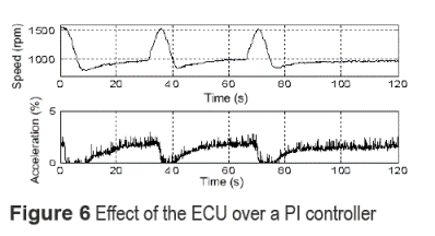
The first strategy explored divided the system into two single input single output (SISO) systems, where engine speed was controlled by the throttle, and torque (or load) by the magnitude of electric current induced in the brake dynamometer. There are different design methodologies of this type of controller, the most common is the Ziegler- Nichols tuning rule [17] for a proportional integral controller (PI), but the damping effect inherent to this type of controller is added to disturbances mentioned above (i.e. turbocharger and ECU), causing unwanted oscillations in engine speed and torque as shown in figure 6. In this case, the independent PI controller could not predict a change in speed produced by the ECU, causing a periodic oscillation.
Decoupled PI action controller
After a couple of tests [18], it was observed that the best control was obtained by compensating the interactions between loops in order to reduce their negative effects. This controller created compensators that cancel interdependent ties of the system by using the matrix of transfer functions described in eq. (1).
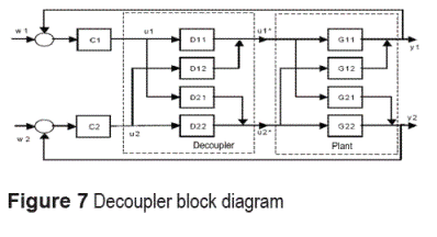
Engine speed was related to accelerator position and torque was related to current in the brake. Those control loops had the highest positive gains. Several procedures to formalize this choice, such as the DC and resonant frequency closed loop gain analysis, were also analyzed [19]. The interdependent loops were the engine speed response caused by electric current in the brake (negative gain), and the torque produced by a change in accelerator. A decoupler used to compensate the effect of the actuator on each variable was designed and implemented. The decoupler consists of a D matrix which converts a multiple input multiple output (MIMO) system into two SISO systems as shown in figure 7. Parameters of the D matrix were obtained experimentally with the procedure described above,resulting: 
Results and discussion
Control system validation
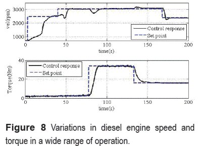
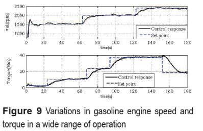
Controller performance was evaluated by setting several engine speed-torque operating modes, including the regions affected by non-modeled dynamics. Figure 8 shows the control response to several set point changes on the diesel engine from 700 to 3.000 rpm and from 2 to 35 Nm. Note the turn on effect of the compressor on the first velocity step and the turn off effect of the fuel pump on the second step, then observe several changes on torque and speed with a good response on the controller. Figure 9 shows the powerful of the control developed in a gasoline engine. The overall stability was not affected even the gasoline engine response is faster than the diesel engine, but the speed presented over damping on the first step due this higher speed response, the next steps did not present over damping because the engine had load. Note that the overshoot in speed due changes in torque is shorter than that of the diesel engine, again this behavior is expected because of its faster response.
Other results
This control system has been used during the last three years in the engine laboratory at the Universidad de Antioquia in Medellín (Colombia). Both engine test beds have been used in order to explore the performance and emissions of diesel and spark ignition engines using several biofuels and its blends with conventional fuels over a wide range of engine operating modes. The use of blends such as E20 (20% ethanol + 80% gasoline) and blends such as B5 and B20 (blends of diesel fuel with 5 and 20% of several indigenous biodiesel fuels have been analyzed using the instrumentation and software herein presented. Those results have been published in several scientific journals [20-24].
When fuels with small concentration of additives are going to be tested, it is very important to assure a very stable engine operation mode, which has been a success with this control system.
Conclusions
A low cost, powerful and robust multivariable control system based on transfer functions was developed, implemented and tested on two internal combustion engines (diesel and spark ignition) test beds. The decoupling matrix D was updated depending on the engine fuel or type, avoiding major changes on the control system. The controller was successfully tested in a wide range of engine operating modes. It could pass through the engine nonlinearities such as turbocharger turning on and some ECU points reaching the stabilization in vicinity points.
The process of designing a decoupled PI controller from a matrix of first order transfer functions with delay for engine speed and torque, met the requirements of control for mid range power engine test beds used for research activities.
Acknowledgments
Authors wish to thank the Colombian Ministry of Agriculture and Rural Development, Sofasa- Renault and El Área Metropolitana del Valle de Aburrá for the financial support of project No. 003 2007D3608-67 (Bioethanol E-20 project) and project 001 2007D3347-499 (Biodiesel). Also our acknowledgements to the Comité para el Desarrollo de la Investigación (CODI) from Universidad de Antioquia for their financial support to both projects mentioned above. The authors also would like to thank the "Sostenibilidad" program 2009 of the Universidad de Antioquia for financial support and professor Orlando Carrillo for his valuable help during engine test beds instrumentation and control system development.
References
1. B. J. Bunker, M. A. Franchek, B. E Thomason. "Robust multivariable control of an engine dynamometer system". IEEE transactions on control systems technology. Vol. 5. 1997. pp. 189-199. [ Links ]
2. M. Plint, A. Martyr. Engine testing: Theory and practice. 3rd ed. Ed. Oxford: Butterworth - Heinemann. Oxford. 1997. pp. 45-190. [ Links ]
3. J. B. Heywood. Internal combustion engine fundamentals. 2nd ed. Ed. Mc.Graw Hill. New York. 1988. pp. 435-472. [ Links ]
4. W. F. Powers. "Internal Combustion Engine control system research at FORD". Memories of the 20th IEEE Conf. on Decision and Control. San Francisco (USA). 1981. pp. 1447-1452. [ Links ]
5. L. A. Del Portillo, F.V. Tinaut, A.M. Bachiller, B. Giménez. "Validación de un modelo fenomenológico para el estudio de motores diesel de inyección directa". Octavo congreso iberoamericano de ingeniería mecánica. Cuzco. 23 - 25 de octubre de 2007. Código 1125. pp. 234-246. [ Links ]
6. K. Lee, K. Park. "Optimal robust control of a contactless brake system using an eddy current". Mechatronics. Vol. 9. 1999. pp. 615 - 631. [ Links ]
7. M. I. Gonzales. "Experiments with eddy currents the eddy current brake". European Journal of Physics. Vol. 25. 2004. pp 463 - 468. [ Links ]
8. A. H. Gosline, G. Campion, V. Hayward. "On the use of eddy current brakes as tunable, fast turn-on viscous dampers for haptic rendering". Proc. Eurohaptics. Paris. 2006. pp 229 - 234. [ Links ]
9. S. Anwar. "A parametric model of an eddy current electric machine for automotive braking applications". IEEE transactions on control systems technology. Vol. 12. 2004. pp 422-427. [ Links ]
10. H. G. Hopkins, R. H. Borcherts, "Discrete time modeling of the torque response of a spark-ignited fuel-injected engine". Applications of adaptive control. Ed. Academic Press. New York. 1980. pp. 491-508. [ Links ]
11. R. L. Morris, R. H. Borcherts, M. V. Warlick, H. G. Hopkins, "Spark ignition engine model building-an identification approach to throttle-torque response," Workshop on Adaptive Control. Detroit (USA). 1981. pp 235-240 [ Links ]
12. J. Cook, B. Powell. "Modeling of an internal combustion engine for control analysis". IEEE power control systems magazine. Vol. 8. 1988. pp. 20-26. [ Links ]
13. B. Kuo. Automatic control systems. 6th ed. Ed. Prentice Hall. New Jersey. 1995. pp 77-117. [ Links ]
14. R C. Dorf, R. H. Bishop. Modern Control Systems. 10th ed. Ed. Pearson Prentice Hall. Upper Saddle River. 2008. pp. 41-142. [ Links ]
15. C. T. Chen. Analog and Digital Control System Design: Transfer-Function, State-Space, and Algebraic Methods. Saunders College Publishing. Philadelphia. 1993. pp. 93-115. [ Links ]
16. ISUZU. Technical manual of the diesel engine ISUZU 4JA1. Tokyo. 1991. pp 65-67. [ Links ]
17. J. G. Ziegler, N. B. Nichols "Optimum settings for automatic controllers". Trans. ASME. Vol. 64. 1942. pp. 759-768. [ Links ]
18. J. D. López. ICE test bed automation. Master thesis (available in Spanish). Universidad de Antioquia. 2009. pp. 21-61. [ Links ]
19. J. J. Espinosa. Control lineal de sistemas multivariables. Ed. Corporación Universitaria de Ibagué. Ibagué. 2003. pp 25-38. [ Links ]
20. P. Benjumea, J. Agudelo, A. Agudelo, "Effect of altitude and palm oil biodiesel fuelling on the performance and combustion characteristics of a HSDI diesel engine", Fuel. Vol.88. 2009. pp. 725 - 731. [ Links ]
21. J Agudelo, P. Benjumea, A. Villegas, "Evaluation of nitrogen oxide emissions and smoke opacity in a HSDI diesel engine fuelled with palm oil biodiesel". Rev. Fac. Ing. Univ. Antioquia. Vol. 51. 2010. pp. 62-71. [ Links ]
22. J. Agudelo, E. Gutiérrez, P. Benjumea, "Experimental combustion analysis of a HSDI diesel engine fuelled with palm oil biodiesel-diesel fuel blends. Dyna. Vol. 159. 2009. 103-113. [ Links ]
23. J. Agudelo, A. Agudelo, J. Pérez, "Energy and exergy analysis of a light duty diesel engine operating at different altitudes". Rev. Fac. Ing. Univ. Antioquia. Vol. 48. 2009. pp. 45-54. [ Links ]
24. J. Agudelo, P. Benjumea, A. Agudelo. "Diagnóstico exergético del proceso de combustión en un motor Diesel". Rev. Fac. Ing. Univ. Antioquia. Vol. 45. 2008. pp. 41-53. [ Links ]
(Recibido el 04 de junio de 2010. Aceptado el 10 de marzo de 2011)
*Autor de correspondencia: teléfono + 57 + 4 + 219 85 59, fax: + 57 + 4 + 211 05 03, correo electrónico: jragude@udea.edu.co (J.R. Agudelo)


