Services on Demand
Journal
Article
Indicators
-
 Cited by SciELO
 -
 Access statistics
Related links
-
 Cited by Google
 -
 Similars in
SciELO
 -
 Similars in Google
Share
Revista Facultad de Ingeniería Universidad de Antioquia
Print version ISSN 0120-6230On-line version ISSN 2422-2844
Rev.fac.ing.univ. Antioquia no.60 Medellín Oct./Dec. 2011
A novel graphical and analytical method for thekinematic analysis of fourth class Assur groups
Un método grafo-analítico para el análisiscinemático de los grupos de Assur de cuarta clase
Héctor Quintero*, Gabriel Calle, Alexander Díaz, Edison Henao
Grupo Procesos de Manufactura y Diseño de Máquinas, Facultad de Ingeniería Mecánica, Universidad Tecnológica de Pereira. Vereda la Julita, A.A. 97. Pereira, Colombia.
Abstract
A method for the kinematic analysis of a fourth class Assur group, using a combination of graphical and analytical methods, is presented in this paper. The solution is obtained through a method in which two special Assur points are used. A mechanism of 1 DOF with a fourth class group is considered as an example to develop the proposed method. The results of this method are in agreement with the results obtained by a dynamic simulation program. Since there are no solutions for fourth class structural groups in the literature, this method allows developing a complete modular procedure for the kinematic analysis of mechanisms, with the methodological advantages that this type of solution offers.
Keywords: Kinematic analysis, fourth class Assur group, structural analysis.
Resumen
En este artículo se presenta un método para el análisis cinemático de un grupo de cuarta clase, utilizando un método grafo-analítico. La solución es obtenida utilizando dos puntos especiales de Assur. Se utiliza como ejemplo un mecanismo de 1 GDL con un grupo de Assur de cuarta clase. Los resultados obtenidos coinciden plenamente con los resultados obtenidos al utilizar un programa de simulación dinámica. Ya que este tipo de tareas para los grupos estructurales de cuarta clase, no se resuelve en la literatura, el método propuesto permite el desarrollo de un análisis modular completo para el análisis cinemático de mecanismos, con las ventajas metodológicas que ofrecen este tipo de soluciones.
Palabras clave: Análisis cinemático, grupo de Assur de cuarta clase, análisis estructural.
Introducción
A planar mechanism can be described with the help of different modules such as the frame, the driver links, and Assur groups of second, third, fourth class, etc. [1]. The essential classification of mechanisms was proposed by L V Assur in1914. This scientist proposed and developed a method for the creation of mechanisms as a consecutive superposition of kinematic chains that have specific structural properties.
Mechanism assembly consists of connecting the group (all the joints that are external to the group) to a base mechanism. The joints are connected to some mobile links, which has a defined movement law, or to the structure of the mechanism. The kinematic analysis (positions, velocities, and accelerations) can be performed through the consecutive determination of each Assur group, when the movement laws of the driving links are given. This method is known as the modular method [2], in which the kinematic equations are formulated and solved separately for each module. The order of the solutions of the equations is defined by the structure of the mechanism. The analysis of positions for each Assur group consists of determining all the possible configurations, when the positions of the external joints and the lengths of the links are given. The solution for second, third and fourth class Assur groups are described in works such as [3-8].
The kinematic analyses for an Assur group consists of determining the angular velocities and accelerations of the links and the linear velocities and accelerations of the internal joints of the group. Kinematic analysis, using graphical methods, for second and third class Assur groups are described in several works [1, 8, 9]. Analytical methods for second and third class groups are described in [3, 9]. Some authors propose numerical methods for the kinematic and dynamic analysis of multibody systems [10] based on natural coordinates. The numerical methods have contributed to the development of dynamic simulation computer programs. Buskiewicz [11] proposes an algorithm that compiles structural and kinematic analysis; this is numerically easy to implement. The kinematic analysis is based on standard kinematic equations that are functions of velocities and accelerations, allowing a modular and kinematic analysis for the different Assur groups that constitute the mechanism.
Kinematic analyses of a fourth class Assur group are studied in several papers [9-12]. For this group is also possible to use analytical methods, formulate the kinematic equations of the group, and then derive them with respect to time [13]. Once the Jacobian matrix is obtained, velocities and accelerations for the group are easy to determine by solving a linear equation system.
From the literature review it is concluded that the grapho-analytical kinematic solutions for the fourth class Assur groups practically do not exist in the specialized literature, that fact makes difficult to develop a complete modular method for this kind of task.
A new method for the kinematic analyses of a fourth class Assur group, based on the combination of graphical and analytical methods, is proposed in this paper. Initially, a graphical procedure is used to determine the velocities and accelerations for points that are special Assur points; there are two special points, one for each link with internal joints (mentioned in this paper as closure links) of the fourth class Assur group. A system of four linear equation is obtained from the kinematic diagrams (velocity or acceleration): two equations for each special point concerned with the relative velocities or the relative accelerations. The system of linear equation has four unknown variables that are the angular velocities or the angular accelerations of the group links. Once the angular velocities or accelerations for the links related to the group are obtained, the velocity or acceleration for any point that belongs to some of their links can be calculated. The proposed procedure is verified in this work by taking as examples one mechanism of a 1 DOF with a fourth class Assur group.
Methodology
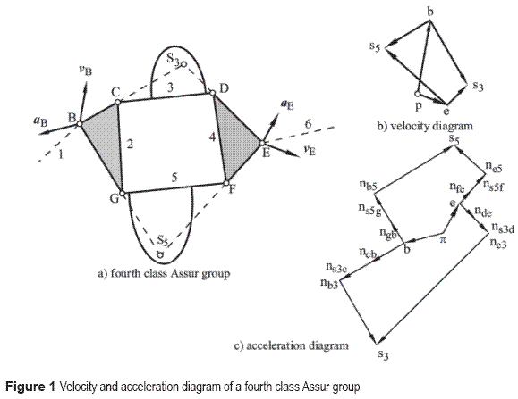
The determination of velocities and accelerations for a fourth class Assur group can be obtained using the Assur special point method. A fourth class Assur group, shown in figure 1.a, consists of two ternary links, called here drag members, two joints, which are an internal and an external joint, and two binary links, both being internal joints. The external joint of the ternary links, as shown in figure 1.a, are joints with links 1 and6 of the base mechanism. Given the velocities and accelerations of the external points of the group, joints B and E of figure 1, the kinematic analysis of a fourth class Assur group consists of determine the angular velocities and accelerations for the links of the group.
The first step of the analysis consists of determining the special Assur points for the binary links of the group with internal joints, links 3 and 5 (called in this paper closure links). The special Assur point of link 3 is obtained by extending line BC, which belongs to link 2, and ED, which belongs to link 4, to find the intersection point S3; this point is considered to belong to link 3. A similar procedure is followed to obtain point S5; this point is considered to belong to link 5. In this case, the point can be found by projecting line BG, which belongs to link 2, and line EF, which belongs to link 4.
Analysis of velocities
Now, it is possible to determine the velocities for points S3 and S5 using the velocity diagram shown in figure 1.b. Therefore, the segments pb and pe can be drawn from point p. These segments represent the given velocities of points B and E, at the chosen scale. The velocity vS3 of point S3 is determined by the vectorial equations given by Eq.1 and Eq. 2:

The last two vectors of each equation can be represented by the same line because both vectors are perpendicular to S3B and S3E, respectively; therefore, vector  is perpendicular to line S3B, and vector
  is perpendicular to line S3E.
Similarly, the vectorial equation for S3 can be formulated using Eq.3 and Eq. 4:

For representing graphically Eq. 3 and Eq. 4, a straight line can be drawn from point b on the velocity diagram, with the direction of the velocity v S3B (perpendicular to S3B). Similarly, from point e, a straight line can be drawn with the direction of the velocity vS3E (vector that is perpendicular to S3E). The intersection point of these two straight lines on the velocity diagram (point s3 from figure 1.b) represents the end of the vector of the velocity vS3 of point S3. The magnitude of the velocity of this point can be obtained by multiplying the distance between points p and s3 by the velocity scale factor chosen, μv:

From the velocity diagram, it is possible to determine the relative velocities vS3B and vS3E:

These relative velocities depend on the angular velocities of the links that constitute the fourth class Assur group. To establish the corresponding equations, it is necessary to assume the directions for the angular velocities. The following relations can be obtained from the velocity diagram, shown in figure 1.b, and by assuming that the angular velocities of links 2 to 5 are clockwise.

In Eq. 7, the direction of velocity vS3B is the same as the direction obtained if the angular velocities of links 2 and 3 were clockwise; therefore, the resultant velocity is positive. In the same way, the relative velocity vS3E of Eq. 8 has the same direction to the one obtained if the angular velocities for links 3 and 4 were clockwise.
The velocity vS5 of point S5, related to link 5, is determined by the formulation of the relative velocity equation with respect to points G and F, Eq. 9 and Eq. 10:

The last two vectors of each equation are located on the same line, because both vectors are perpendicular to S5B or to S5E; this means that vector  is perpendicular to S5B and vector
  is perpendicular to S5E.
Similarly to the velocity vectorial equations for point S3, the vectorial equation system for S5 can be described through Eqs.11 and 12:

For the graphical representation of these equations, figure 1.b, a straight line can be drawn from point b on the velocity diagram with the direction of velocity vS5B (perpendicular to S5B). Similarly, a straight line is drawn from point e with the direction of the vector for the velocity vS5E (perpendicular to S5E). The intersection point of these two straight lines on the velocity diagram (point s5 in figure 1.b) represents the end of the vector for the velocity vS5 of point S5. The magnitude of the velocity of this point can be obtained by multiplying the length of line ps5 by the velocity scale factor:

Then, from the velocity diagram, it is possible to determine the relative velocities vS5B and vS5E

Similar to the analysis of the velocity diagram of point S3, the relative velocities vS5B and vS5E depend also on the direction of the angular velocities for links 2, 3, 4, and 5. Considering all the angular velocities clockwise, the following equations are given:

In both equations, the relative velocities are positive because the directions of velocities vS5B and vS5E are the same as the direction obtained if the angular velocities for links 2, 3, 4, and 5 were clockwise. Solving the system of linear equation given by Eqs. 7, 8, 15, and 16 simultaneously, the angular velocities for the links 2, 3, 4, and 5 are determined.
Analysis of accelerations
The solution to the analysis of accelerations for a fourth class Assur group with two drag members can be obtained in a similar manner to the velocities solution. As in the analysis for velocities, it is necessary to make use of the special points S3, related to link 3, and S5, related to link 5.
Taking an arbitrary point π (figure 1.c) as a pole and as a starting point for segments πb and πe for the accelerations diagram, the segments πb and πe can be drawn; these segments represent the accelerations αB and αE at the chosen scale μα for points B and E. The acceleration αS3 of the special point S3 can be determined by using Eqs. 17 and 18:
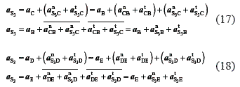
In Eqs. 17 and 18, the sums of the normal and tangential accelerations are shown as vectors αnS3B, αnS3E, αtS3B and, αtS3E because the directions of their components are the same. The magnitudes for the relative normal accelerations are determined by:

The directions for these vectors can also be determined by the same methods already mentioned. As the direction of both tangential components, for each vectorial equation, are the same, it is not necessary to determine the magnitude of each components. To calculate the resultant of the sum of the tangential components, drawing vector action line for the tangential accelerations from the ends of the normal accelerations αnS3B, αnS3E is sufficient. For this purpose, segments bnb3 and ene3 can be drawn from points b and e, obtained from the acceleration diagram; these are the representations for the accelerations αnS3B and αnS3E (at scale μα).
Then, straight lines are drawn in the direction of the tangential accelerations αtS3B and αtS3E from points nb3 and ne3, which are perpendicular to lines S3B and S3E, respectively. Point s3, where these two lines intersect, is the end of vector αS3; the magnitude of the absolute acceleration of point S3 is determined by:

From the acceleration diagram, it is now possible to determine the magnitude of the relative accelerations αtS3B and αtS3E:

The senses for the relative tangential accelerations and the angular accelerations follow the same procedure described for the velocity case. These relative tangential accelerations depend on the angular accelerations of the links that constitute the fourth class group. For this case, all the angular accelerations are assumed clockwise. The following relations are obtained from the accelerations diagram:

The tangential acceleration is positive in the former equation, because the direction of the acceleration αtS3B is the same as the one that the angular accelerations for links 2 and 3 would have if they were clockwise. In the second case, the relative tangential acceleration αtS3E has opposite direction to the one that would be obtained if the angular accelerations for links 3 and 4 were clockwise; this is the reason for the negative sign.
The acceleration αS5 from the special point S5 is determined by using Eqs. 24 and 25:
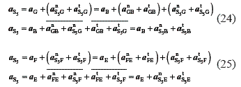
In Eqs. 24 and 25 the sums of the normal and tangential accelerations are shown as resultant vectors αnS5B, αnS5E, αtS5B and, αtS5E as the directions of their components are equal. The magnitudes of the normal accelerations are determined as usual, making use of Eq. 26:

The direction of the normal acceleration vectors is also determined by the same methods already mentioned. In the acceleration diagram, tangential accelerations are drawn from the ends of the normal accelerations αnS5B and αnS5E. The directions of these vectors are perpendicular to the vectors of the normal accelerations. For this purpose, segments bnb5 and ene5 are drawn starting on points b and e. These segments are obtained from the acceleration diagram and are the representations for the accelerations αnS5B and αnS5E.
Then, straight lines are drawn from points nb3 and ne3 in the direction of the accelerations αtS5B and αtS5E, which are perpendicular to S5B and S5E respectively. Point s5, which is the intersection point of these two lines, is the end of vector αS5 from the resultant acceleration of point S5, whose magnitude is determined by:

Repeating the procedure for the relative accelerations of point S3, the magnitude of the relative accelerations αtS5B and αtS5E are determined from the acceleration diagram, multiplying by the acceleration scale factor

Now, these relative tangential accelerations depend on the angular accelerations of the links that constitute the fourth class group. Taking into account that all the angular accelerations are assumed clockwise, the following relations are obtained from the accelerations diagram:

In Eqs. 29 the relative tangential accelerations αtS5B are opposite to one that angular accelerations of links 2 and 5 were clockwise. For that reason, it is necessary to write the negative sign in Eqs. 29.
From the simultaneous solution of the systems of linear equation given by Eqs. 22, 23, 29, and 30, the angular accelerations for the links that constitute the fourth class group can be determined.
Results
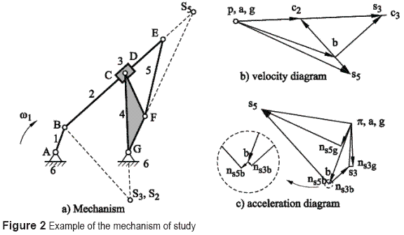
In the present section, a mechanism R - (RRP -RRR) of 1 DOF is considered as example. Figure 2.a shows the representation of a mechanismcomprised by driving link 1, fixed link 6, and afourth class group (links 2, 3, 4, and 5). Links 2and 4 are the ternary links of the group, and jointsB and G are the joints that connect the group tothe base mechanism. Links 3 and 5 join to the twodrag links.
The lengths of the links are: LAG = 275 mm, LAB= 100 mm, LBE= 500 mm, LEF= 300 mm, LGD= 300 mm, LFG= 150 mm, and LFD = 180 mm; the angular velocity of link 1 is ω1 = 1 rad/s. The additional lengths required for the analysis of velocities and accelerations are obtained from the positions diagram. The additional lengths are the distances measured from the joints to the special points S3 and S5: LBS3 = 248.0601 mm, LDS3= 481.9848 mm, LFS5= 436.2923 mm, and LES5= 155.1123 mm.
For the kinematic analysis of the fourth class Assur group, it is necessary to determine the special point S3, which belongs to link 3, and point S5, which belongs to link 5. Link 3 has a prismatic joint with link 2 and one rotation joint with link 4. The procedure to locate the special point requires a modification with respect to the case in which the link with internal joints has only rotation joints. The special point of link 3 must be such that, when formulating the relative velocities equation, the unknown velocities are parallel. Observing that the relative movement between links 2 and 3 is parallel to link 3, the special point must be located on a line that is perpendicular to link 2 and that intercepts point B. Point S3 is located on the intersection between a line that is perpendicular to the relative movement between links 2 and 3 and the projection of line GD of link 4; point D represents the rotation joint between links 4 and 3. Point S2 is the point of link2 concurrent to point S3.
The binary link 5 joins with the ternary links (2 and 4) with rotation joints. Point S5 is the intersection point when line BE related to link 2and line GF related to link 4 are projected.
Analysis of velocities: Figure 2.b shows the velocities diagram of the mechanism.
The solution for the driving link is:

The equations for the velocity of point S3 related to link 3 are obtained using the equation of relative velocities from joints S2 and D:

The velocities vS2B and vS3S2 are parallel, because vS2B is perpendicular to line BS2, and vS3S2 isparallel to link 2. As BS2 is perpendicular to link2, they can be drawn together as is presented inEq. 33. A similar procedure is given for velocities vDG and vS3G, which are perpendicular to line DG.
For link 5, special point S5 has to be determined, by projecting lines BE and GF. The procedure to determine the velocity of point S5 is the same as the one followed for point S3; that is, using relative velocities from points E and F:

Point S5 is chosen so that the velocities vEB and vS5E become parallel, as vFG and vS5F.
Figure 2.b shows the velocities diagram, which is useful to solve the velocities at points S3 and S5. The distance between points s3 and b (from the velocities diagram) gives the sum of the relative velocities vS2B and vS3S2. Assuming clockwise angular velocities for links 2 and 3 the relative movement between links 2 and 3 from left to right (observed from link 2), the following equation results:

where the distance between points b and s3 is represented by line  ; its magnitude is obtained by multiplying it by the scale actor µV. If the direction of the angular velocity of link 2is assumed clockwise, then the direction of the relative velocity vS2B is opposite to the resultant velocity
  . A Similar procedure is followed for the other velocities:

If the angular velocities of links 3 and 4 are assumed clockwise, the relative velocities vDG and vS3D have opposite directions. Then, in Eq.36, the latter relative velocity vS3D is negative. Next, the equations for the relative velocities related to point S5 can be formulated as:

In the linear equation systems given by Eqs. 35, 36, 37 and 38, the unknown variables are the angular velocities ω2, ω4, and ω5 and the relative velocity between links 2 and 3, vS3S2. This system of equations can now be solved. The distances LBS3, LES5, and LFS5 can be taken from the positions diagram. The solution for the system of equations gives the following results:
ω2 = 0.0086 rad/s, ω4 = 0.4746 rad/s, ω5 = 0.1104 rad/s, vS3S2 = 61.5254 mm/s.
Analysis for accelerations: Figure 2.c represents the acceleration diagram for the mechanism.
The first step consists of solving the driving link.
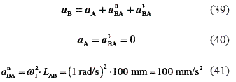
The direction of the acceleration αnBA is from point B to point A. Next, the accelerations of point S3, related to link 3, and S5, related to link 5, are determined.

where  , the direction is from point D to E
αtS2B= α2 . LS2B, that is perpendicular to line BS2
 , the direction of this component is obtained by rotating the vector vS3S2 through of angle of 90° in the direction of the angular velocity ω2 (the direction is opposite to that of the component αnS2B).
α ρS3D is parallel to link 2.
In Eq. 42, the accelerations αtDE and α ρS3S2 are unknown. The components αnS2B and αcS3S2 are parallel due to the method to find point S3 (this point is located on line DE). A similar case occurs with the components αtDE and α ρS3S2. Making use of this condition, Eq.42 can be formulated as:

Figure 2.c shows the representation for αnS2B + αcS3S2 through line bns3b. As this component has opposite direction, its total magnitude can be obtained by subtracting both components in the direction of line bs3. The resultant tangential acceleration αtS3B (perpendicular to the normal acceleration) is represented through point ns3b. A second equation is determined for point S3:

where
 , from D to G
αtDG= α4 . LS3D, that is perpendicular to DG
 , from S3 to D
αtS3D= α3 . LS3D, perpendicular to line S3D
In this equation, the tangential accelerations are unknown. Due to the method used to find point S3 (this point is located on line DG), the normal components αnDG and αnS3D and the tangential components αtDG and αtS3D are parallel. Makinguse of this condition, Eq. 44 can be expressed as:

The normal acceleration αnS3G is represented through the segment gnS3g on the accelerations diagram. Here, the normal accelerations are subtracted by each other and the resultant acceleration can be found. The component αtS3G is represented through a line drawn from point nS3e, perpendicular to the normal component αnS3G. The point of intersection of the lines that represent the relative tangential accelerations is the point of the acceleration of point S3, αS3.
Two equations are needed to find the acceleration S5 (S5 belongs to link 5). These equations are taken from the relative accelerations between points S5 and E, and between points S5 and F:

where  the direction of this acceleration is given by line FG
αtFG= α4. LFG, that is perpendicular to line FG
 , with direction from S5 to F
αtS5F= α5. LS5F that is perpendicular to line S5F
Due to the parallelism condition, Eq. 46 can be reduced to:

where αnS5G=αnFG + αnS5F is represented through line gns5g; the magnitude is obtained by adding the normal components from F to G, and the tangential acceleration  is represented from point ns5g, and it is perpendicular to the direction of the normal acceleration.
Taking relative accelerations between points E and S5:

where  , from E to B
αtEB= α2 . LEB, perpendicular to line EB
 , from S5 to E
αtS5E= α5. LS5E, perpendicular to line S5E
Making use of the parallelism condition, Eq. 48 can be formulated as:

where αnS5B= αnEB + αnS5E is represented through line bns5b; the magnitude is obtained by adding the normal components from E to B, and the tangential acceleration  is represented from point ns5b, and it is perpendicular to the direction of the normal acceleration.
Figure 2.c represents the graphical procedure for the accelerations of points S3 and S5. The expressions for the relative tangential accelerations are obtained from the accelerations diagram. To determine the equations, the angular accelerations for links 2, 3, 4, and 5 are assumed to be counterclockwise, and the relative acceleration α ρS3S2 from left to right.
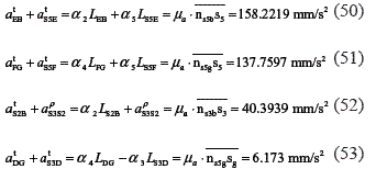
In the system of linear equations given by Eqs.50 to 53, it is necessary to analyze the directions of the tangential accelerations in order to assign the matching sign. In these set of equations, the variables are: the angular accelerations α2, α3 = α2, α4, and α5 and the relative acceleration α ρS3S2. Solving the set of equations yields:
α2 = α3 = 0.2663 rad/s2, α4 = 0.4485 rad/s2, α5 = 0.1616 rad/s2, and α ρS3S2 = -25.6695 m/s2
Conclusions
A method that uses a combination of analytical and graphical methods to perform the kinematic analysis of a fourth class Assur group was presented in this paper. Special Assur points, which are points that belong to the links with internal joints, are used in the proposed solution.
An example that comprised a mechanisms R – (RRR – RRR) was presented to show the application of the proposed method; the solution for this example was verified using a commercial software and classical analytical methods. The results obtained demonstrate the reliability of the proposed method.
The developed method can be used for the kinematic analysis of planar mechanisms with one, two, or three degrees of freedom, including such groups. This method allows developing a modular method for the kinematic analysis of mechanisms. This is especially appropriate for pedagogical purposes.
Referencias
1. I. I. Artobolevski. Theory of Mechanisms and Machines. Ed. Nauka. Moscow. Russian. 1988. pp. 52-63. [ Links ]
2. P. Fanghella, C. Galleti. "A modular method for computational kinematics". Computational Kinematics. J. Angeles, G. Hommel and P. Kovacs (editors). Ed. Kluwer. Dordrecht. 1993. pp. 275-284. [ Links ]
3. G. Calle, A. Diaz, H. F. Quintero. Análisis cinemático de mecanismos planos a partir del análisis estructural según Assur. V Congreso Iberoamericano de Ingeniería Mecánica. Merida. Venezuela. Octubre 23-26. 2001. pp. 1231-1240. [ Links ]
4. S. Mitsi, K. D. Bouzakis, G. Mansour. "Position analysis in polynomial form of planar mechanism with an Assur group of class 4 including one prismatic joint". Mech. And Mach. Theory. Vol. 39. 2004. pp. 237-245. [ Links ]
5. W. Y. Cheng. "The position analysis of Assur kinematicchain with five links". Mech. and Mach. Theory. Vol.40. 2005. pp. 1015-1029. [ Links ]
6. S. Mitsi, K. D. Bouzakis, G. Mansour, I. Popescu. "Position analysis in polynomial form of class-three Assur". Mech. and Mach. Theory. Vol. 43. 2008. pp. 1401-1415. [ Links ]
7. K. Romaniak. Methodology of the Assur Groups Creation. 12th IFToMM World Congress. Besançon, France. June 18-21. 2007. pp. 1- 5. [ Links ]
8. G. G. Baránov. Curso de la teoría de Mecanismos y Máquinas. Ed. Mir. Barcelona. 1979. pp. 46-82. [ Links ]
9. Mashinostroyenye: Enciclopedy in 40 Vols. Dynamic and Strength of machines. Theory of Mechanisms and Machines. Vols. 1-3. Book 2. Ed. Mashinostroyenye. Moscú. 1995. pp. 415-417. [ Links ]
10. R. Brock, H. Dresig, C. Hammerschmidt, B. Hüther, E. Huhn, W. Ihme, P. Jacobi, G. Jokisch, W. Müller,M. Schulze, G. Thiel. "Kinematische Analyse ebener Mechanismen". Getriebetechnik Lehrbuch. J. Volmer. (editor). 1a ed. Ed. Verl Technik. Berlin. 1987. pp. 166-168. [ Links ]
11. J. Buskiewicz. "A method of optimization of solving a kinematic problem with the use of structural analysis algorithm (SAM)". Mech. and Mach. Theory. Vol. 41. 2006. pp. 823-837 [ Links ]
12. L. T. Dvornikov, S. P. Starikov. "Kinematics and kinetostatics of Assur's flat six-section group of the fourth class". Mech. and Mach. Theory. Vol. 4. 2006. pp. 61-65. [ Links ]
13. M. Z. Kolovsky, A. N. Evggrafov, Y. U. Semenov, A. V. Slousch. Advanced Theory of Mechanisms and Machines. Ed. Springer. Berlin. 2000. pp. 79-85. [ Links ]
(Recibido el 4 de junio de 2010. Aceptado el 13 de abril de 2011)
*Autor de correspondencia: teléfono: + 57 + 6 + 313 71 24, fax: + 57 + 6 + 313 72 92, correo electrónico: hquinte@utp.edu.co (H. Quintero)


