Serviços Personalizados
Journal
Artigo
Indicadores
-
 Citado por SciELO
 -
 Acessos
Links relacionados
-
 Citado por Google
 -
 Similares em
SciELO
 -
 Similares em Google
Compartilhar
Revista Facultad de Ingeniería Universidad de Antioquia
versão impressa ISSN 0120-6230
Rev.fac.ing.univ. Antioquia no.64 Medellín jul./set. 2012
ARTÍCULO ORIGINAL
Voltage space vector's computation for current control in three phase converters
Cómputo del vector espacial de voltaje para control de corriente en convertidores trifásicos
Alberto Berzov*, Julio Viola, José Restrepo
Universidad Simón Bolívar. Edificio ELE, PB, Oficina 019. Valle de Sartenejas, Caracas, Venezuela.
*Autor de correspondencia: teléfono: + 058 + 212+906 4012, correo electrónico: aberzoy@usb.ve (A. Berzoy)
(Recibido el 24 de marzo de 2011. Aceptado el 3 de septiembre de 2012)
Abstract
This work presents two current loop techniques, for three phase voltage source converters (VSC) used as controlled rectifiers (CR) operating at unity power factor. The first one is based on choosing the best natural vector, among the natural space vectors produced by two level voltage source inverters, with the use of a cost function. The second one is based on computing and synthesizing a space vector such that an absolute minimum in the cost function is obtained. The first algorithm is a simple method that presents power factor correction and good total harmonic distortion compensation. The second algorithm provides a novel and closed form formula to calculate the optimum voltage vector applied by the converter. In this method, pulse width modulation (PWM) is required to modulate the voltage vector that controls directly the line current, to follow the current reference. The simulations and experimental results show the advantages of the proposed control algorithm.
Keywords: Current control, active filter, power factor, predictive control
Resumen
Este trabajo presenta dos técnicas de control de corriente para convertidores trifásicos de voltaje trabajando como rectificadores controlados, operando con factor de potencia unitario. El primer algoritmo está basado en la escogencia del mejor vector natural, entre los 7 vectores espaciales naturales del convertidor de dos niveles de voltaje trifásico, mediante una función de costo. El segundo está basado en el cómputo y síntesis del vector espacial óptimo de convertidores trifásicos tal que se obtiene el vector que proporciona un mínimo absoluto de la función de costo. El primer algoritmo es un método sencillo que controla muy bien el factor de potencia y presenta una considerable compensación del contenido armónico. El segundo algoritmo provee una nueva fórmula cerrada para calcular el vector de voltaje óptimo aplicado al convertidor. Para este segundo método se necesita generar la señal de control con un modulador de ancho de pulso para así controlar directamente la corriente de línea permitiendo seguir la referencia de corriente. Las simulaciones y resultados experimentales muestran las ventajas del algoritmo propuesto.
Palabras clave: Control de corriente, filtro activo, factor de potencia, control predictivo
Introduction
Nowadays almost every electric and electronic device is powered by a bridge diode rectifier which is a source of harmonics in the line current. These harmonic components deform the line current, create voltage unbalances, voltage losses in the point of common coupling and cause power inefficiency. International Standard IEC 61000–3-2 establishes limits for harmonic currents content in equipment drawing less than 16A per phase from the mains. The International Standard IEC 61000-3-12 deals with levels of harmonic currents injected by equipment drawing between 16A and 75A per phase. Both standards can be met by adding passive power filters using simple and robust circuitry. Those filters, however, are not capable of operating in all the input range and do not guarantee sinusoidal input currents.
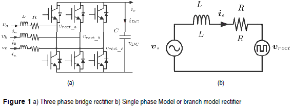
In order to solve these problems, single and three phase voltage source converters have been proposed and investigated as controlled rectifiers [1-8] and active power filters (APF) [9-15], Active power filters play and important function in reducing harmonic current contamination in lines providing a wide range of operation and almost perfect sinusoidal input current in both, single and three phase equipment. The topology used in this paper is a voltage source converter (VSC) shown in figura 1, that can be used as controlled rectifier or active power filter, while using the same proposed algorithm. An additional feature obtained with this converter topology is the possibility of power regeneration from the DC bus to the supply grid.
Different techniques have been proposed to perform the control of these converters which can be classified in: direct current control [8, 10–12, 14, 15], voltage oriented control [6], virtual flux orientation control [16], direct power control (DPC) [2, 3], The control technique proposed in [3] have some interesting advantages, such as high dynamic response, basic open loop operation, low sensibility to parameter variations and simplicity in implementation.
Using the advantages of the DPC algorithm shown in [3], this paper presents a simple technique based on predictive current control, combining the advantages of direct current control and predictive DPC. Additionally to its simplicity, the control algorithm does not require the computation of the active and reactive power as in DPC, and achieves a similar result.
Three phase converter
The three-phase two-level voltage source converter used as controlled rectifier with voltage output is shown in figura 1a, which is composed of three well defined structures: three inductors with its parasitic resistance acting as coupling between the AC sources and the converter active front end, a three-phase bridge composed of six IGBTs and a DC bus with its corresponding capacitor. To develop the mathematical model of the rectifier shown in figura 1a, it is useful to suppose that each phase of the rectifier can be represented as the circuit depicted in figura 1b.
From the circuit in figura 1a and using space vector notation the following equation is obtained:

where  S is the line voltage space vector,
  S is the line current space vector and
  rect is the converter's voltage space vector.
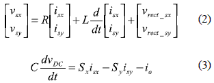
Decomposing (1), the model of the controlled rectifier in ''xy'' coordinates is:
where:

Control strategies
Converter's vector selection
Equation (1) represents the converter's model. A discrete time version of this equation is obtained by the following first order approach:

The line current space vector can be expressed as:

where  s(k) is the present sampled value of line current vector and
  s(k+1) is the estimated value for line current at the next control cycle. Δt = TS is the control period. From (5):

by replacing (7) in (6) and neglecting the resistive component of the input inductance, the next current value will be:

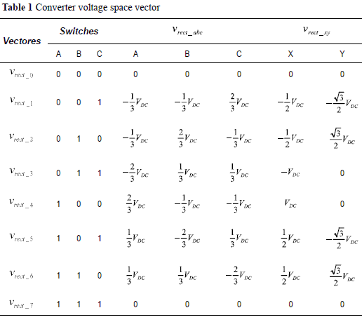
Equation (8) is an estimate of the next line current value which depends of the VSC's voltage space vector  rect. Depending on the switching states,
  rect has 7 possible space vectors shown in table 1.
The current error is defined as the difference between the reference current and the measured line current:

In order to get unity power factor operation the current taken by the controlled rectifier from the mains must be a scaled version of the sinusoidal line voltage. The current reference will be then:

where G is a scale factor used to build the current reference from the measured line voltage. For G>0 the rectifier will operate in direct mode carrying power from the grid to the load at unity power factor, while for G<0 the power flow is from the DC link to the grid at unity power factor.
Replacing the reference in (9), the current error can be written as:

The current error in the next control cycle can be estimated as:

In a similar manner as the line current vector described in (6), the line voltage can be written as:

For a sinusoidal voltage source power supply, the estimated  s(k+1) is obtained by rotating
  s(k) in Δφ = ωTS rads.

where ω is the AC line frequency. The estimated error which predicts the current error in the next control cycle is:

Decomposing the vector expression for the current error into ''x-y'' components, results:

If the zero magnitude vector is applied by the controlled rectifier the error expressions become:

Replacing (17) in (16) leads to:

where the sub index ''n'' goes from 1 to 6.
Once that each converter's voltage vector error is calculated, the control has to select which one minimize the error. This is achieved by minimizing the following cost function:

The chosen vector is the one that minimizes the cost function value J(k+1)_n.
Computation of optimum converter's vector
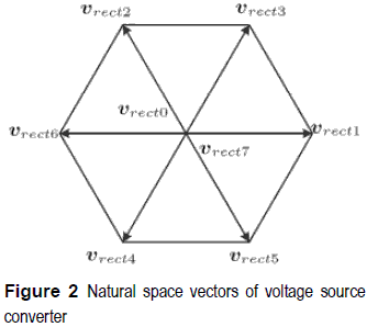
If PWM is used to control the converter then the space vector modulation (SVM) technique can be used to synthesize any vector, in an average sense, inside the hexagon area shown in figura 2. By doing this, an extra degree of freedom is available and an optimum synthesized vector can be obtained so that the cost function is minimized to zero, and so the corresponding current errors. Zero is an absolute mnimum of the cost function, and is obtained when the current error components in (19) are zero [3]. Using this minimum (15) becomes:

where

By using Euler's formula in (21) and decomposing in x-y components result:

Additionally considering (13) and (14), and assuming a sampling frequency much higher than the line frequency the variation in line voltage Δ s(k) value can be neglected and (21) can be written as:

Then
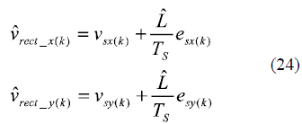
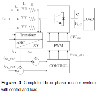
Figure 3 shows the complete system:
Simulated and experimental results
The simulations are executed on the SimPowerSystems toolbox of Simulink Matlab. For the experimental tests, an IGBT based three phase two-level VSC configured as a controlled rectifier, is implemented in a semi custom test rig [17]. This test bench is controlled by a digital signal processor (DSP) ADSP-21369 running at 40MHz where the algorithms are programmed on a personal computer, using the manufacturer's compiler for that DSP. Table 2 shows the experimental set-up parameters that were also used in the simulations. The inductor value was calculated to ensure maximum power transfer between the AC supply and the rectifier [18]. The DC-link voltage value was set to be equal to twice the value obtained in an uncontrolled rectifier.
The experiments for both control algorithms, vector selection and optimum vector, were the following:
Rectifier with a fixed reference current
In this experiment a reference line current of 2.5% of the voltage source vs, is
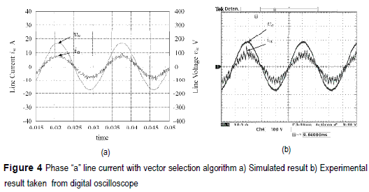
is = 4.25 A, was employed. Figure 4 shows the phase A line current, synchronized with the corresponding line voltage, for the vector selection algorithm. Figure 5a depicts the simulation results obtained with Matlab and figure 5b the experimental one taken with a digital oscilloscope Tektronix TDS3054. Both plots show that the controlled rectifier is operating at unit power factor.
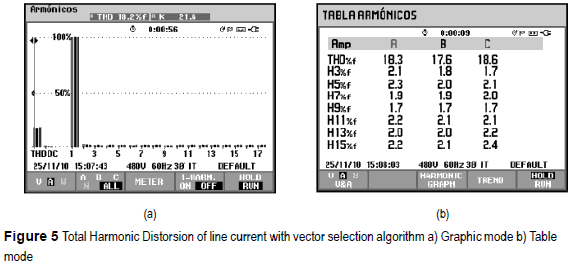
Figure 5a shows the total harmonic distortion (THD) of 18.2% for the experimental results, for the vector selection algorithm, taken from a Fluke Power Quality Analyzer 434. The control doesn't compensate completely the harmonic component however it accomplishes the harmonic levels required for the IEC 61000-3-2 standard holding the power factor near to the unity. The figure 5b is a table with the contribution of most important harmonic components.
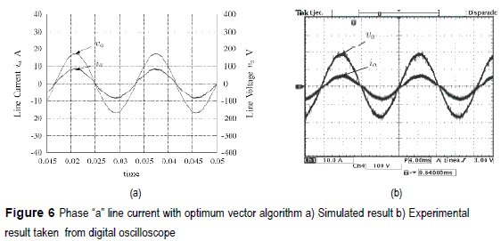
Identical test conditions are used for the optimum vector algorithm. Figure 6 presents the response of this control, the figure 6a shows the simulation result and figure 6b shows the experimental one taken by the same digital oscilloscope as figure 4b. It is demonstrated that this algorithm reduce considerably the harmonic contents of the current holding a unit power factor.
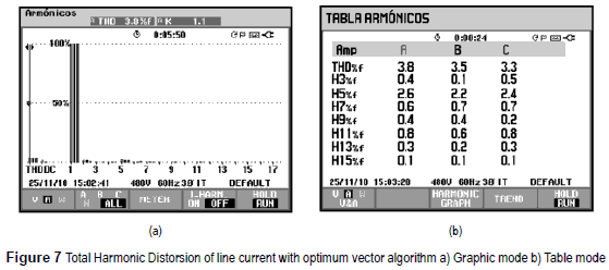
Figure 7a and 7b show a THD of 3.8% which is coherent with the results in figure 6 In comparison with the previous algorithm, this method presents a better performace as expected, because the greater number of available voltage vectors, limited only by the resolution of the pulse width modulator, compared with the 7 natural vectors used in the first method.
Rectifier with a step reference current
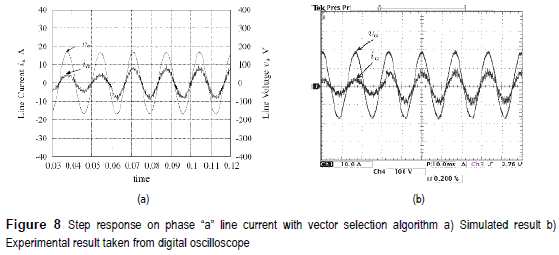
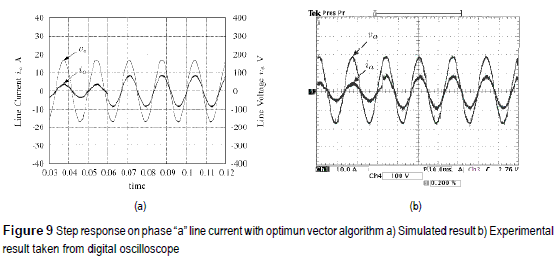
A step response test is applied to the two proposed strategies. The step is performed in the ''abc'' coordinates, where G=0.005 is changed to G=0.01 at 0.06 seconds. The initial current is 1.25% of the line voltage and after 0.06 seconds the current changed to 2.5% of the same line voltage. That means a 100% step change applied to the reference signal.
Figures 8a and 8b present the step response of simulated and experimental tests for the vector selection algorithm respectively. Both figures show a fast response which demonstrates the dynamic of the control algorithm.
Figures 9a and 9b present the step response of simulated and experimental tests for the optimum vector algorithm respectively. As the results presented in figures 8a and 8b, the algorithm shows a very good dynamic keeping harmonic compensation and power factor correction.
Regenerative rectifier
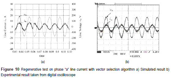
For this test is necessary to feed the filter capacitor with a bridge diode rectifier. This test shows the voltage source converter acting as inverter or regenerative rectifier delivering energy to the line. The reference is changed from G=0.005 (rectifier mode) to G=-0.005 (inverter mode) in 0.06 seconds.
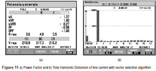
Figures 10a and 10b present the simulated and the experimental results for the vector selection algorithm for the test explained previously. Both figures depict the change of the phase showing a power factor of -0.98 as it can be seen in figure 11a.
Figure 11b shows the total harmonic distortion of the inversion test. The THD is 19.7% which is coherent with the THD obtained in the experimental result with fixed current reference of figure 4a.
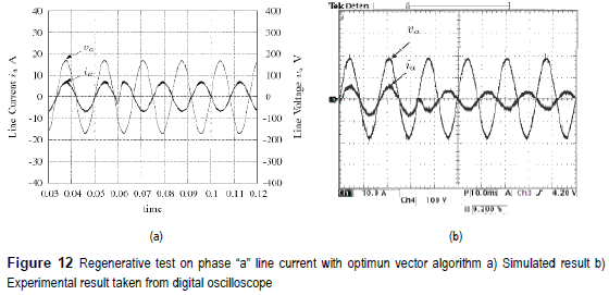
Figures 12a and 12b present the simulated and the experimental results for the optimum vector algorithm. As with the other algorithm, the change of phase takes less than 1ms, showing a very good dynamic response.
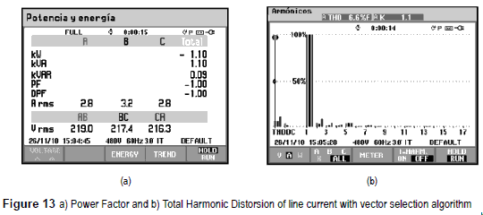
Figures 13a shows the power factor of -1 which corresponds to the inversion of phase. Figure 13b shows the total harmonic distortion of the regenerative test resulting in a THD of 6.6%.
Conclusions
Two methods to control the input current loop in a three phase VSC used as controlled rectifier are proposed. The first method uses a cost function to select the best vector from the seven natural voltage space vectors available. This method is simple requiring only the evaluation of expressions (18) and (19) seven times per control cycle. The results obtained show a THD in the order of 18% when the controlled rectifier is operating at unity power factor in direct mode. The harmonic levels obtained in the line current are below of limits stated in IEC 61000-3-2 standard.
An improved version of the first method is implemented using PWMto synthesize the optimum vector that reduces a quadratic cost function to zero. Provided that the control variable has more possible values, not just seven vectors, the results show a smaller current ripple and THD values smaller than 4% accomplishing also the IEC 61000-3-2 standard.
The dynamic response of both methods is also tested at unity power factor when the power flow direction is reverted and when the current reference is suddenly changed showing a transient time smaller than 1ms.
This method has a similar response as direct power control without computing active and reactive powers. It directly controls the current and indirectly the power of the system.
References
1. J. Rodriguez, J. Pontt C. Silva. P. Correa. P. Lezana, P. Cortés, U. Ammann. ''''Predictive Current Control of a Voltage Source Inverter''. IEEE Transactions on Industrial Electronics. Vol. 54. 2007. pp. 495- 503. [ Links ]
2. T. Noguchi, H. Tomiki, S. Kondo. I. Takahashi. ''Direct Power Control of PWM converter without power-source voltage sensors''. IEEE Trans, on Ind. Applications. No. 3. 1998. pp. 473-479. [ Links ]
3. J. Restrepo. J. Aller. J. Viola. A. Bueno. G. Habetler. ''Optimum Space Vector Computation Technique for Direct Power Control''. IEEE Transactions on Power Electronics. No. 6. 2009. pp. 1637-1645. [ Links ]
4. A. Berzoy. M. Strefezza. ''Optimized Fuzzy Variable Structure for a Three-Phase Rectifier with power factor correction''. WSEAS Transactions on Power Electronics. No. 8. 2009. pp. 275-284. [ Links ]
5. M. Montero. E. Cadaval. V. Marcos. M. Martinez. Three-phase PWAI Sinusoidal Current Rectifier with Power Conditioning Capability. 35th Annual Conference of IEEE Industrial Electronics. IECON 09. Porto. Portugal. 2009. pp. 3703 - 3708. [ Links ]
6. F. Huerta, S. Stynski, S. Cóbreces, M. Malinowski, F. Rodríguez. Conft-ol of Three-Phase Rectifiers Based on Voltage Equation of the PWM Converter. 35th Annual Conference of IEEE Industrial Electronics, IECON '09. Porto, Portugal. 2009. pp. 328 - 333. [ Links ]
7. W. Xu, H. Kaizheng, Y. Shijie, X. Bin. Simulation of Three-Phase Voltage Source PWAI Rectifier Based on Direct Current Control. Congress on Image and Signal Processing, 2008. CISP '08. Tianjin, China. 2008. pp.194-198. [ Links ]
8. T. Reddy, T. Rao, M. Kumar. Simulation of 13. Direct Current Controlled PWiXI Rectifier Feeding to Adjustable Speed Drives. International Conference on Advances in Computing. Control. & Telecommunication Technologies. 2009. Trivandrum, Kerala. India, pp. 540-544. [ Links ]
9. S. Rahmani, N. Mendalek, K. Al-Haddad. ''Experimental Design of a Nonlinear Control Technique for Three-Phase Shunt Active Power Filter''. IEEE Transactions on Industrial Electronics. No. 10. 2010. pp. 3364-3375. [ Links ]
10. O. Vodyalcho, D. Hackstein. A. Steimel. T. Kim. Novel Direct Current-Space-Vector Conti-ol for shunt active power filters based on three-Level inverters. 23th Annual IEEE Applied Power Electronics Conference and Exposition. Austing, Texas. 2008. pp. 1868-1873. [ Links ]
11. D. Nedeljkovic. M. Nemec. K. Drobnic, V. Ambrozic. Direct current control of active power filter without filter current measurement. Power Electronics. Electrical Drives. Automation and Motion. SPEED AM 2008. International Symposium on. Ischia. Italy. 2008. pp. 72-76. [ Links ]
12. D. Nedeljkovic. M. Nemec. V. Ambrozic. Three- Phase Parallel Active Power Filter with Direct Current Control. 12th International Power Electronics and Motion Control Conference. Portoroz, Slovenia. 2006. pp.1660-1664. [ Links ]
13. C. Townsend. C. Rowe. T. Summers. T. Wylie. Predictive current control of an Active Harmonic Filter. Power Engineering Conference. AUPEC 08. Australasian Universities. Sydney. Australia. 14-17 December 2008. pp. 1-6. [ Links ]
14. H. Qiu. Y. Zhongdong. L. Qiao. S. Renzhong. A Direct Current Cont>-ol of Shunt Active Power Filter. International Conference on Energy and Environment Technology. ICEET 09. Guilin. China. 2009. pp. 7-10. [ Links ]
15. W. Lenwari, M. Odavic. A comparative study of two high performance current control techniques for three-phase shunt active power filters. International Conference on Power Electronics and Drive Systems. PEDS 2009. Taipei. Taiwan. 2009. pp. 962-966. [ Links ]
16. M. Malinowski. M. Kazmierkowski, S. Hansen. F. Blaabjerg. G. Marques. ''Virtual Flux-Based Direct Power Control of Three-Phase PWM Rectifiers''. IEEE Trans, on Ind. Applications. No. 4. 2001. pp. 1019-1027. [ Links ]
17. M. Giménez, V. Guzman. J. Restrepo. J. Aller. J. Viola. A. Bueno. PLATAFORKIA: A Useful Tool for High Level Education, Research and Development. Proceedings of the 7th International Caribbean Conference on Devices. Circuits and Systems. Cancun. Mexico. 2008. pp. 28-30. [ Links ]
18. J. Das. Power System Analysis Short-Circuit Load Flow and Harmonics. Ed. Marcel Dekker. Inc. New York. United States. ''Reactive Power Flow and Control''. 2002. pp. 434-447. [ Links ]


