Serviços Personalizados
Journal
Artigo
Indicadores
-
 Citado por SciELO
 -
 Acessos
Links relacionados
-
 Citado por Google
 -
 Similares em
SciELO
 -
 Similares em Google
Compartilhar
Revista Facultad de Ingeniería Universidad de Antioquia
versão impressa ISSN 0120-6230
Rev.fac.ing.univ. Antioquia no.66 Medellín jan./mar. 2013
ARTÍCULO ORIGINAL
Active and reactive power flow regulation for a grid connected VSC based on fuzzy controllers
Regulación del flujo de potencia activa y reactiva en un convertidor VSC conectado a red mediante controladores difusos
Nelson Díaz Aldcmcí, César Leonardo Trujillo, José Guillermo Guarnizo
Laboratorio de Investigación en Fuentes Alternativas de Energía del Departamento de Ingeniería Electrónica, Universidad Distrital Francisco José de Caldas, Carrera 7 N° 40-53 Piso 5, Bogotá, Colombia.
*Autor de correspondencia: teléfono: + 57 + 1 + 323 93 00 ext. 1402, correo electrónico: nldiaza@udistrital.edu.co (N. Díaz)
(Recibido el 1 de noviembre de 2012. Aceptado el 09 de febrero de 2013)
Abstract
Voltage Source Converters (VSC) are one of the most used converters in distributed generation application and HVDC systems, since a VSC can operate either as inverter or rectifier. Furthermore, a VSC allows fast, accurate and independent active and reactive power flow control. However, a VSC is a double- input double-output non-linear control objet, therefore; nonlinear control strategies can be useful in order to obtain desired behaviors. In particular, knowledge based fuzzy controller does not require a mathematic model of the system it just relies on a qualitative knowledge about the behavior of the system. Moreover, the same fuzzy controller can be applied to any VSC with any power ratio. This paper presents the analysis, design and results obtained by using fuzzy controllers for regulating the active and reactive power flow in a Voltage Source Converter (VSC) connected to the utility grid. Additionally, it is shown that the transitory and stationary response of the VSC depends on the shape of membership functions at different power ratios. Digital simulation was performed in order to verify the behavior of the controller under different power levels. Finally, a VSC prototype with fuzzy controllers was tested experimentally.
Keywords: Voltage source converter, fuzzy control, membership functions, grid connected system
Resumen
Los convertidores de fuente de tención (VSC) son una de las topologías más utilizadas en sistemas de generación distribuida y sistemas de transmisión de alta tensión en corriente continua (HVDC). Esto, gracias a que el VSC puede operar como rectificador o como inversor. Adicionalmente, un VSC permite un control rápido preciso e independiente de del flujo de potencia activa y reactiva. Sin embargo, el VSC es un sistema de control no lineal, acoplado de dos entradas y dos salidas, por lo tanto, estrategias de control no lineales pueden resultar eficientes y simples de diseñar. En particular, el control difuso basado en conocimiento no requiere modelos matemáticos del sistema a controlar ya que este se basa en el conocimiento cualitativo que se tenga del comportamiento del sistema. Por lo tanto, el mismo controlador difuso se puede utilizar para diferentes convertidores VSC conectados a red, bajo diferentes niveles de transferencia de potencia. Este artículo, presenta el análisis, diseño y resultados de la implementación de controladores difusos para la regulación del flujo de potencia activa y reactiva de un VSC conectado a red. Además, se muestra la dependencia de la respuesta transitoria y de estado estacionario con la forma de las funciones de pertenencia del controlador difuso cuando este se aplica a diferentes niveles de transferencia de potencia. El desempeño de los controladores se verifica mediante simulación y mediante implementación física en un prototipo construido de un VSC.
Palabras clave: Convertidor VSC, control difuso, funciones de pertenencia, sistema conectado a red
Introduction
Within the last few years, the increasing rate of renewable energy resources and new requirements of energy, have aimed to more efficient and reliable way of convert and share energy. In this sense, micro-grids appear as a possibility in order to generate and manage energy flow adequately [1]. Indeed, energy resources are not usually close to the consumption center then, it has to be delivered long distances and it has to be integrated to conventional energy distribution systems. Even if the energy generator is close to the load it is necessary a conversion in order to match the requirements of the load.
Therefore, it is necessary to use adequate interfaces that allow interconnecting sources of different characteristics to the power grid [2], For instance, if the energy source is DC, it is necessary to turn the DC voltage into AC voltage with frequency, amplitude and phase required for grid interconnection. On the other hand, if the source of energy is AC, it is also necessary a synchronization [2].
A voltage source converter (VSC) is a power electronics based converter, capable of operating either like an inverter as well as rectifier. The main function of a VSC is converting a DC voltage into an AC current or an AC voltage into a DC current [3], Forthat reason, it can be used to couple a DC power source such as a photovoltaic generator, to an AC grid. Additionally, a VSC can be used to couple an AC power source, such as a wind generator, to a DC link, and the DC link can be coupled to an AC power grid by means another VSC such as in HVDC systems [3, 4],
When a VSC is connected to an active load, the power flow between the active load and the VSC can be controlled by adjusting the amplitude and phase of the generated voltage [5, 6]. As a matter of fact, the behavior of a grid connected VSC is similar to a synchronous generator [3], However, in a VSC, the active and reactive power flow, are basically non-linear coupled control objects [5, 7], In that case, control methodologies based on mathematic an analytical models might result complex [8], In addition, analytical models may not accurately represent the dynamic behavior of the VSC under different conditions of operation. In this sense, intelligent nonlinear controllers could overcome the disadvantages of linear controllers. In particular, the use of fuzzy logic has become more important due to its adaptability with high nonlinearities, and applicability in systems where model is unknown or even mathematically complex [9, 10].
In this paper are proposed knowledge based fuzzy controllers applied to a VSC in order to regulate the power flow. In the first place, is analyzed the behavior of a grid connected VSC and its power flow. Next, the qualitative knowledge about the behavior of the system is synthetized by means of linguistic fuzzy rules of the type (if-then) in order to obtain the power flow controllers. After that, simulation result for two different VSCs are shown, it will be demonstrated that the same qualitative knowledge can be applied to any VSC with any power ratio. Finally, physical implementation of knowledge base fuzzy controllers to control independently the active and reactive power flow is tested.
VSC basic operation
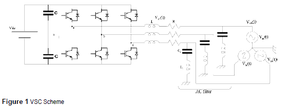
A two level inverter bridge is the most common topology used for VSC. The bridge is composed by 3 arms in which each one, is equipped by two self-commutating switches (IGBTs commonly) as shown in figure 1 [5], The diodes allow an inverse flow of the current, and finally a converter- reactor per phase, which becomes the linkage between the VSC and the AC load, complements a grid-connected system. Additionally, there are capacitors at the DC side which have two basic functions; energy storage, and filtering high frequency components [5]. The basic scheme of a VSC is shown in figure 1, where the DC sources represent the voltage of a bus DC or even a DC generator.
The main advantage of a VSC is that its switches can be commuted at any time by appropriate gate voltage. Therefore, the generated voltage wave can be easily adjusted and modified. Nevertheless, when the transistors in each arm are switched alternatively, it is important to regard dead times in order to prevent short circuit during commutation of the switches in the branch [3],
By Sinusoidal Pulse Wide Modulation (SPWM) control signals and subsequent filtering of high frequency components, a sinusoidal AC voltage can virtually be generated at any angle and any amplitude [8, 10], Therefore, it is possible to generate the three-phase waves with the correspondent phase shift in each arm [11 - 13], The fundamental components of the outputs voltages in each phase are:
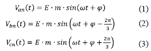
Where (E=Vdc /2) is the voltage in the DC side of the converter in each pole, Van is the output voltage in the phase a, m is the modulation ratio that is the relationship between the peak output voltage and the DC voltage m = Emax/E, ω is the angular frequency and φ is the phase shift between the generated three-phase voltage and the utility grid.
Because of the feasibility and simplicity to control the generated AC voltage waves at any phase, amplitude and frequency, VSCs are highly used in distributed generation systems, HVDC's and motor drivers.
Grid-Connected VSC analysis
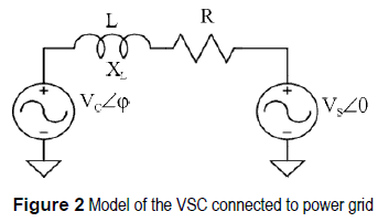
When the VSC is connected to a power grid (active load), the active and reactive power flow can independently be controlled manipulating the phase and amplitude of the AC voltage generated by the VSC with respect to the AC grid voltage [12 - 14]. The VSC connected to a power grid behaves like the stator of a synchronous machine as shown in figure 2. This assumption can be made regarding fundamental frequency component only. For that reason, the VSC can almost instantaneously control the active power and reactive power flow between generator and active load.
Then, the active power P and reactive power Q flow between the converter and the power grid, are expressed as in (4) and (5). These expressions can be obtained by means of a phasorial analysis.

Where Vc is the RMS value of the fundamental component of the converter voltage, Vs is the RMS value of the fundamental component of the AC grid voltage, X is the reactance of the reactor that connects the two voltage sources, φ is the phase shift between Vc and Vs. In addition, at (4) and (5) R, which is the resistance of the line, is neglected in order to simplify the analysis [11]; this assumption can be done taking into account that in a good design, the power losses of the VSC are usually less than 5% of the rated capacity [7]. Moreover, analysis done in a precedent work shows that in this range the expressions (4) and (5) are a good approximation [8].
Equations (4) and (5) show that P depends on the phase shift (φ) mainly and Q depends on the Vc amplitude mainly -Vc is controlled by the modulation ratio m-. In light of the above, it is possible to control independently the active and reactive power by adjusting the values of φ and m respectively [15].
Using SPWM signals to control the VSC and generated an AC wave voltage with any phase and amplitude, permits a flexible control of power flow. In fact, some authors have proposed that active and reactive power flow between a VSC and power grid can be controlled independently by φ and m respectively [16]. However, the relationships between φ and P and between m and Q are basically nonlinear [8]. Consequently, a nonlinear control strategy may be more desirable rather than conventional linear controllers in order to obtain good response in a wide range of operation of VSC.
Power flow fuzzy controllers
Lineal control theory uses mathematical models of a process and some specifications of the expected behavior in close loop, to design a controller [9]. These control strategies are highly used in systems that can be assumed as linear in certain range of their operation. Besides, it is absolutely necessary to obtain a linear model that represents the relationship between input and output in order to design the controller [17].
However, for some systems it is difficult to find out that linear model. Sometimes, it is necessary to use sophisticated tools of identification in order to find out a linear input-output transfer function [8]. Despite this, the found out model only describes the system in a narrow range accurately. In addition, when the system does not have constant parameters or has interdependence with others parameters the found out model is less accurate.
Given the above points, linear control strategies could be limited in design and performance. On the other hand, non-linear strategies such as knowledge Based Fuzzy Control (KBFC) [10], outperform linear controllers in many of the cases exposed above. KBFC is based on human knowledge which adds several types of information and can mix different control strategies that can not easily be added through an analytical control law. On top of that, like human knowledge, KBFC does not need an accurate mathematical model in order to work out a control action [9]. What is more, KBFC uses the experience and the knowledge of an expert about the behavior of the system in order to work out the control action.
A kind of KBFC is the rule-based fuzzy control, where the human knowledge is approximated by means of linguistic fuzzy rules in the form if- then. Each rule describes the control action in a particular condition of the system [9]. -Control action that would be done by a human operator [9]-.Therefore, under a specific condition of the system (if condition1) can be specified an action (then action1).
A rule base can be defined throughout different conditions of a system in which each rule defines an action for a specific condition. In the same way, both condition and action are represented by linguistic terms such as (large, medium, small) for condition and (increase a few, increase a lot) for actions, those linguistic terms belong to fuzzy sets with overlapped boundaries. Therefore, by means of fuzzy sets it is possible to get smooth interpolation between different rules, in order to describe completely the behavior of the system with few rules [9]. That characteristic allows the fuzzy control to represent the qualitative knowledge of a human expert [9].
Due to the nonlinear behavior showed by the converter and supported in the advantages of fuzzy control exposed before, nonlinear fuzzy controllers might be desirable to control the active and reactive power independently by manipulating φ and m respectively. Then, two PD fuzzy controllers (emulating PD linear controllers) [9] in feedback mode were proposed, one for P under variations of φ (Δφ), and the second one for Q under variations of m (Δm).
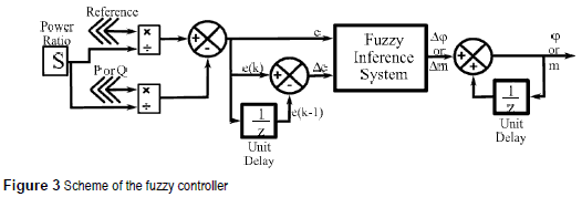
The controllers are based on a Mamdani fuzzy inference system, that kind of controllers are usually used into feedback systems because the rule base represents a static mapping between antecedents and consequents [10]. The antecedents of the inference system are the error (e) and the change at the error (Δe = e(k)-e(K-1)) and the consequents are the change at φ (Δφ), and the change at (Δm); for P and Q respectively. Therefore, the linguistic rules can be described as follows:
If e is (big, small, etc.), and Δe is (big, small, etc.) then φ or m (increases, decreases, etc).
Consequently, it is necessary to introduce pre and post-filters at each controller in order to achieve the derivative input Δe, and the accumulative effect at the output. In addition, it is absolutely convenient to work with normalized inputs at the fuzzy inference system in order to apply the controller to different power ratios [9]. Then, the inputs of the controllers should be scaled by the power ratio of the converter (S). To be more precise, the normalized domain for the error at the controller of active power is (-2, 2), since the converter should be able to change from rectifier to inverter or vice versa. Whereas, the normalized domain for the error at the controller of reactive power is (-1, 1), since Q should be remained near to zero. Finally, the scheme of the controller is shown at figure 3.
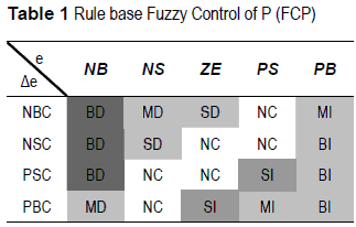
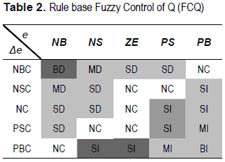
Into the fuzzy inference system, there are defined the rule base and the membership functions that provide a smooth interface between linguistic terms and numerical variables. Five linguistic terms are defined for the error input (e) in both controllers (negative big (NB), negative small (NS), zero error (ZE), positive small (PS), and positive big (PB)), four for the change at the error input (Δe) in the controller for P (negative big change (NBC), negative small change (NSC), positive small change (PSC), and positive big change (PBC)), and an additional membership function is required for the change at the error input (Δe) in the controller for Q (No Change (NC)). This membership function avoids instability when the power flow changes suddenly - take into account that the system is coupled, so, a change in P affects Q-. Besides, seven linguistic terms were defined for the output (big decrement (BD), medium decrement (MD), small decrement (SD), no change (NC), small increment (SI), medium increment (MI), and big increment (BI)). In particular, the amount of linguistic terms for each process variable, were selected based on the qualitative knowledge of the system. In table 1 and table 2 are summarized the rule base for the fuzzy control of P (FCP) and the fuzzy control of Q (FCQ) respectively.
In the same way, the membership functions were tuned based on the desired behavior - minimum error in steady state and minimum oscillation in transitory state-. There were used triangular and trapezoidal membership functions because of, they are simpler computationally [10]. Accordingly, figure 4 shows the membership function for FCP and figure 5 shows the membership function of FCQ.
Simulation results
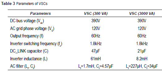
To verify the performance of the controllers, a simulation bench was built in SimPowerSystem toolbox ofMatlab. In addition, two different VSC 's with different power ratio were dimensioned in order to verify the behavior of the controllers under systems with different power ratio. The first VSC is a 3 00VA system and the second one is a 3kVA system. It is supposed a balanced behavior at the 3 phasic systems; therefore, simulation results just show the behavior of the system in one phase. In table 3 are summarized the main parameter of both tested systems.
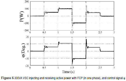
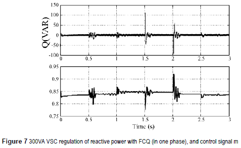
The figure 6 shows the response of the 3 00VA VSC under changes at the power flow. It is possible to see that the VSC is able to follow the reference (0, 50, 100, -100, 50 and 0 W) in either mode, like inverter or rectifier. In figure 6 are also shown the response of the controller, and how the phase shift (φ) changes in order to reach the reference. Likewise, figure 7 shows the reactive power flow control, and how the modulation index is adjusted by the controller seeking to maintain the reactive power flow close to zero.
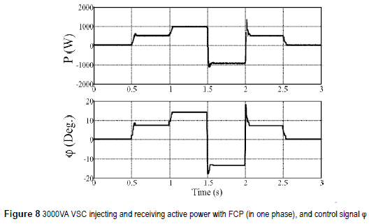
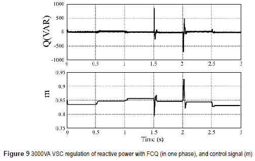
Besides, figure 8 shows the response of the 3,000VA VSC under changes at the power flow (0, 500, 1,000, -1,000, 500 and 0 W). Figure 8 also shows the way in which the phase shift (φ) is adjusted by the controller. Similarly, figure 9 presents the reactive power flow regulation and how the modulation index (m) is adjusted by the controller.
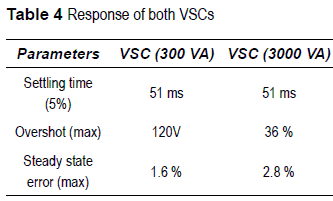
The table 4 summarizes the main characteristics of systems is pretty similar, there are necessary near the response of the systems with fuzzy controllers. 3 cycles to obtain the steady state. However, the At table 4 we can see that the settling time at both dynamic responses and steady state error vary.
On top of that, figures 6 and 8 show that the control objective is reached accurately, in spite of differences at the dynamic of both systems. Additionally, from figures figures 7 and 9, it is possible to realize, that the system is not decoupled, and that hard changes at the active power flow affects the reactive power flow control deeply.
In particular, this behavior was regarded at the moment of dimensioning the domain of the fuzzy variables. First of all, the maximum value of ±5 for (Δφ) was selected in order to avoid hard changes at the active power flow that could perturb the reactive power flow control. Second, despite the control of Q should always keeping this value in zero, peaks at the response can reach the rate power values, for that reason the domain of the control of Q should regard the entire power ratio (-1,1). Finally, variations at the modulation index are not greater than 0.1, so changes at (m) are restricted between ±0.05. In short, it was absolutely necessary to know the behavior of the system in order to synthesize the controllers.
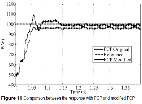
Apart from that, the stationary error increases when the power ratio increases. This fact can be solved by adjusting the membership function NS, ZE and PS. However, a change on the membership function will affect the dynamic response of the system. The figure 10 shows a comparison between the original FCP and a modified FCP in which the membership function NS, ZE and PS have been modified.
Figure 10 shows a reduction in the steady state error and changes at the dynamic response by using the modified FCP. In light of the above, the performance of the system would be improved if additional uncertainty is added to the shape of membership functions, when the power ratio varies. In this sense, type-2 fuzzy sets allow us to incorporate additional uncertainty to membership functions by defining them as fuzzy membership functions [18, 19]. To conclude, that approach should be addressed and evaluated at future works.
Experimental results
Toverify the developedcontrollers experimentally, a 300VA VSC prototype was implemented. The data acquisition board PCI 6024E of N.I. and the software Real Time Windows Target of MATLAB has been used for the implementation of the fuzzy controllers.
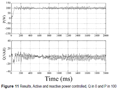
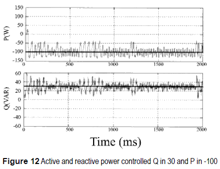
In short, figure 11 shows the response of one phase of the VSC in real implementation. First, figure 11(a), shows the VSC transferring 100W to the AC network, at the same time, the reactive power flow is regulated close to zero (figure 11(b)). Likewise, figure 12 shows the case when the AC network transfers power to the DC side of the VSC (figure 12(a)). Additionally, figure 12(b) shows an inductive behavior at the VSC, where the reactive power flow is regulated around 30VAR (the reference of FCQ was changed intentionally in order to verify the behavior of the controller).
From figures 11 and 12 it is possible to see that the response of the system follows the reference at both controller (FCP and FCQ). However, it is also evident that signals have high degree of oscillation. That sort of behavior is very common in power systems due to a variety of interactions among components and the heavy power transfer across interconnections that often create damping problems [20].
Conclusion
In this paper non-linear fuzzy controller were designed in order to control the active and reactive power flow in a VSC connected to the grid. The knowledge base fuzzy controller does not require and elaborated mathematic model of the converter, it just requires a detailed knowledge about the behavior of the system. Therefore, the same controllers can be applied to any VSC at any power ratio just by normalizing the inputs of the controller with respect to the power ratio.
When power ratio increases, the steady state error also increases. However, the steady state error can be reduced by adjusting the shape of membership functions. Additionally, changes at membership functions modify the dynamic response of the system. Consequently, if the shape of the membership functions is adjusted it would be possible to modify the steady state error and dynamic responses such as overshot and damping. Fort that reason, type 2 fuzzy controller should be addressed in future works.
Finally, it was demonstrated that despite the VSC is a nonlinear coupled double-input doubleoutput control object, P and Q can be controlled independently. Nevertheless, the coupling between P and Q should be regarded at the control of Q.
References
1. Y. Ruan, Q. Liu, W. Zhoun R. Firestone, W. Gao, T. Watanabe. "Optimal option of distributed generation technologies for various commercial buildings". Applied Energy. Vol. 86. 2009. pp.1641-53. [ Links ]
2. F. Blaabjerg, R. Teodorescu, M. Liserre, A. Tirnbus. "Overview of control and grid synchronization for distributed power generation systems". IEEE Transactions on Industrial Electronics. Vol. 53. 2006. pp. 1398-1409. [ Links ]
3. V. Sood. "HVDC and FACTS controllers". Kluwer power electronics and power editions series. Boston, Unite State of America. 2004. pp. 26-38. [ Links ]
4. O. Gomis, A. Junyent, A. Sumper, S. Galceran. "Maximum generation power evaluation of variable frequency offshore wind farms when connected to a single power converter". Applied Energy. Vol. 87. 2010. pp. 3103-09. [ Links ]
5. S. Ruihua, Z. Chao, L. Ruomei, Z. Xiaoxin. "VSCs based HVDC and its control strategy". IEEE/PES Transmission and Distribution Conference and Exhibition: Asia and Pacific. Dalian, China. 2005. pp. 1-6. [ Links ]
6. L. Guangkai, L. Gengyin, L. Haifeng, Z. Chengyong, Y. Ming. "Research on Dynamic Characteristics of VSC-HVDC System". IEEE Power Engineering Society General Meeting. Montreal, Quebec, Canada. 2006. pp. 1-5. [ Links ]
7. G. Zhang, Z. Xu, G. Wang. "A linear and decoupled control strategy for VSC based HVDC system". IEEE/ PES Transmission and Distribution Conference and Exposition Atlanta, Georgia, Unite State of America. Vol. 1.2001. pp. 14-19. [ Links ]
8. C. Trujillo, D. Velasco, J. Guarnizo, N. Diaz. "Design and implementation of a VSC for interconnection with power grids, using the method of identification the system through state space for the calculation of controllers". Applied Energy. Vol. 88. 2011. pp. 3169-75. [ Links ]
9. R. Babuscka. "Fuzzy and neural control disc course lecture notes". Delft University of Technology. Delft, the Netherlands. 2009. pp. 1-56. [ Links ]
10. N. Diaz, F. Barbosa, C. Trujillo. "Analysis and design of a nonlinear fuzzy controller applied to a VSC to control the active and reactive power flow". In: Electronics, robotics and automotive mechanics conference. CERMA. Cuemavaca, Morelos Mexico. 2007. pp. 417-22. [ Links ]
11. G. Zhang, Z. Xu. "Steady-state model for VSC based HVDC and its controller design". IEEE Power Engineering Society Winter Meeting. Vol. 3. Columbus, Ohio, Unite Estate of America. 2001. pp. 1085-90. [ Links ]
12. K. Padiyar, N. Prabhu. "Modeling, control design and analysis of VSC based HVDC transmission systems". International Conference on Power System Technology. PowerCon. Singapore. 2004. pp. 774-79. [ Links ]
13. L. González, G. Garcerá, E. Figueres, R. González. "Effects of the PWM carrier signals synchronization on the DC-link current in back-to-back converters". Applied Energy. Vol. 87. 2010. pp. 2491-2499. [ Links ]
14. Gengyin, Z. Ming, H. Jie, L. Guangkai, L. Haifeng. "Power Flow Calculation of Power System Incorporating VSC-HVDC". International Conference on Power System Technology. Singapore. PowerCon 2004. pp. 1562-1566. [ Links ]
15. G. Li, G. Li, H. Liang, C. Zhao, M. Yin. "Research on dynamic characteristics of VSC-HVDC system". IEEE Power Engineering Society General Meeting. Montreal, Quebec, Canada. 2006. pp. 1-6. [ Links ]
16. J. Liu, M. Han, X. Chen. "Development of VSC HVDC quasi-steady-state model and its application". International Conference on Sustainable Power Generation and Supply, 2009. SUPERGEN '09. Nanjing, China. 2009. pp. 1-4. [ Links ]
17. K. Astrom, R. Murray. Feedback Systems: An Introduction for Scientists and Engineers. Princeton University Press. Princeton, New Jersey, Unite Estate of America. 2010. pp. 131-164. [ Links ]
18. L. Zadeh. "The Concept of a Linguistic Variable and Its Application to Approximate Reasoning-1". Information Sciences. Vol. 8. 1975. pp. 199-249. [ Links ]
19. H. Chamorro, N. Diaz, J. Soriano, H. Espitia. "Active and reactive power flow fuzzy controller for VSC HVDC using DBR and DBR type 2". Annual Meeting of the North American Fuzzy Information Processing Society (NAFIPS). El Paso, Texas, Unite Estate of America. 2011. pp.1-6. [ Links ]
20. J. Paserba. "Robust control in power systems [book reviews]". Power and Energy Magazine, IEEE. Vol. 5. 2007. pp. 79-81. [ Links ]


