Serviços Personalizados
Journal
Artigo
Indicadores
-
 Citado por SciELO
 -
 Acessos
Links relacionados
-
 Citado por Google
 -
 Similares em
SciELO
 -
 Similares em Google
Compartilhar
Revista Facultad de Ingeniería Universidad de Antioquia
versão impressa ISSN 0120-6230
Rev.fac.ing.univ. Antioquia no.68 Medellín jul./set. 2013
ARTÍCULO ORIGINAL
Molecular dynamics simulations of nanoindentation in Cr, Ni, and Ni/Cr bilayer films using a hard spherical potential
Simulación por dinámica molecular de nanoindentación de películas Cr, Ni y bicapas de Ni/Cr usando un potencial de esfera dura
Sebastian Amaya Roncando1, Elisabeth Restrepo Parra1, Diego Fernando Arias Mateus2*, Mónica María Gómez Hermida2, Juan Carlos Riaño Rojas1
1PCM-Computational Applications, Universidad Nacional de Colombia. C.P. 111321. Manizales, Colombia.
2Grupo GEMA, Universidad Católica de Pereira. A.A. 2435. Pereira, Colombia.
*Autor de correspondencia: teléfono: + 57 + 6 + 312 40 00, fax: + 57 + 6 + 31 27 613, correo electrónico: diego.arias@ucp.edu.co (D. Arias)
(Recibido el 15 de Agosto de 2012. Aceptado el 5 de Agosto de 2013)
Abstract
Molecular dynamics (MD) simulations of nanoindentation using the hard sphere potential were carried out for Cr, Ni and Ni/Cr bilayer thin films with interaction of BCC and FCC single-crystal and the contact between the Cr- Ni. On the other hand, fixed boundary conditions were used and the repulsive radial potential was employed for modeling the interaction between the tip and sample surface. Mechanical properties of the material at 300 K were obtained for Cr and Ni thin films and Ni/Cr bilayers. Hardness and elastic parameters were determined from the load-unload curves obtained by means of the simulations. These results show a better mechanical response in the case of bilayers compared to the Ni and Cr monolayers.
Keywords:Molecular dynamics, nanoindentation, Cr film, Ni film, bilayer
Resumen
Se empleó la simulación por dinámica molecular de nanoindentación usando el potencial de esfera dura en películas delgadas de Cr, Ni y bicapa de Ni/ Cr con interacción mono-cristal BCC y FCC y contacto entre el Cr y Ni. Por otro lado, se consideraron condiciones de frontera fijas y el potencial radial repulsivo fue usado para modelar la indentación entre la punta y la superficie de la muestra. Propiedades mecánicas del material a 300 K fueron obtenidas para las películas delgadas de Cr, Ni y bicapa de Ni/Cr. Los parámetros elásticos y de dureza fueron obtenidos de las curvas de carga y descarga generadas de la simulación. Estos resultados muestran una mejor respuesta mecánica en la bicapa comparado con las monocapas de películas delgadas de Ni y Cr.
Palabras clave: Dinámica molecular, nanoindentación, película de Cr, película de Ni, bicapa
Introduction
Thin films have been widely used for improving the contact surfaces performance in applications such as magnetic storage and microelectromechanisms (MEMS) [1, 2]. Nevertheless, there is a remarkable difference between monolayer and multilayer films; a monolayer is strongly influenced by the interfaces that normally improve the mechanical performance. In order to understand these differences, a surface study in thin films is required.
The nanoindentation has been widely used for measuring mechanical properties of thin films, because this technique employs small loads (in the order of nanonewtons-nN) and thicknesses not greater than nanometers. In this method, an indenter with a well-known geometry placed in contact with the sample surface applying a load is used.
For this type of test (in the order of nanometers) several complex and expensive equipment are required. It makes the tests highly expensive and normally they take long time. These difficulties have been overcome by using molecular dynamics (MD) simulations [3]. MD is a powerful tool for studying material properties in areas as bioscience, chemistry, material science among others. Because of the computer technology development, simulations with millions of atoms are currently possible.
Recently, several works that implement MD for simulating nanoindentation processes in order to study mechanical properties in thin films have been carried out. Iizuka et al [4] has used MD simulations for studying the relationship between thin films of aluminum and silicon substrates [4]. Shi and Falk applied MD for studying the structural transformation and atoms localization during the nanoindentation process in crystalline and metallic thin films [5]. Liu et al, simulated the nanoindentation of diamond and gold thin films studying the load, load speed and temperature effects on the mechanical properties of the system [6]. The thin films-substrate system was studied [7] analyzing the hardness and deformation during the nanoindentation. In the Fang and Wu work, the deformation, contact and adhesion of an Al/Ni multilayer system was analyzed by means of MD [8].
The principal aim of this work is to study the Cr and Ni thin films deformation, comparing these results with those obtained in the case of Cr/Ni bilayers. The Morse interatomic potential is used for describing the interaction between the atoms of the system. The nanoindentation process is simulated by using molecular dynamics.
Computational model
The model used in this work consists of the construction of a spherical indenter ideally non- deformable, with radius of 3 nm. This equation denotes the repulsive spherical potential between the rigid sphere (the indenter) and the atoms belonging to the sample. In this equation R and r.. represent the indenter radius and the distance between the center of the indenter and each atom of the simple placed in the position j. K represents the hardness of the indenter that in this case is considered as the diamond. The exponent 3 in this equation is the first odd power that represents the harmonic type interaction. It means that any atom that comes into contact with the indenter will be repelled in the direction of the sphere movement, generating the effect of displacement or indenter penetration.
The sample contains a layer of Ni atoms with FCC crystalline structure oriented in the plane (100) and a layer of Cr with BCC (100) structure. Values of lattice parameters are shown in table 1.
The parameter alpha (α), also named fitting parameter is the dimensionless parameter of the Morse equation. This parameter allows finding the lowest energy value ofthe interaction between atoms not only of the same type, but also of the different type. Because of the potential employed is numerical, the parameter alpha represents the lowest value for which two neighbor atoms can be considered as bond atoms. Moreover, this parameter also controls the width of the energy well for which there is a bond. As is observed in the paper, for finding the alpha parameter of as for example CrN, it is necessary to fit values with the Eq. (4). Then, this parameter depends on the atoms interacting named control material parameter.
Sample dimensions are 14.45 Å in the x-y plane and 28.9 Å in the z axis. During the collision of energetic particles of a solid, the temperature of the system is experiencing a peak related to the change of the instantaneous kinetic energy of each atom within the network. This change is caused by the collision of each particle with its neighbors and for this reason is necessary to implement a numerical model that is responsible for controlling the change in energy of these particles in order to stabilize the thermally [9]. For crystalline materials, the computational box is usually generated by an algorithm which executes repetitions of the unit crystal cell along each dimension until the required system size is obtained. The constraints of computer power force MD simulations to employ small systems of atoms and hence it is important to choose a computational cell large enough to minimize any finite-size effects. Boundary conditions of [10] are employed to maintain as accurately as possible the realistic physical behaviour of the simulated material. Hence, boundary conditions serve to mimic the influence of bulk material surrounding the computational cell. This ensures that physically meaningful properties of the material can be obtained from simulations employing a small number of atoms.
When there are no restrictions on the dynamics of an atom (typically atoms central to the simulated phenomena) then free boundary conditions are usually applied. Fixed or rigid conditions can be applied to edge atoms to constrain the vertical or horizontal motion of the computational cell. An atom is simply made rigid by not integrating the equations of motion for that particular atom. However, although the fixed atoms are sited away from the centre of interest, they can be a problem by creating an artificial interface between the rigid atoms and the dynamic atoms [11].
Boundary conditions are fixed in the x-y plane and in the lower face, while free boundary conditions were used in the upper face of the sample. The Indentation was carried out controlling the nanoindenter position (pulling it down) depending on the applied load and the repulsive potential. This repulsive potential is described by:

where K and R represent the sphere stiffness and sphere radius respectively and rij is the distance between the center of the spherical nanoindenter and the sample atoms [10]. In this case, K has a value of 4.5ev/Å3 and R is 3 nm. In this work, the Morse interatomic potential is used for describing the interaction between all the atoms in the sample. Generally this potential is given by the equation:

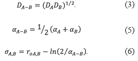
For a like Morse system, Dij is the bond dissociation energy; it means, the equilibrium energy between bonded atoms. rij, r0 are the system interatomic and equilibrium distances. In this model, the interaction distance for each atom is considered up to three times the lattice parameter. Note that in equation (2) the distance between non-interacting atoms is not considering. This distance is called cutoff radius and is used to improve computational time calculation. α is the fitted parameter of the material that depends on the binding tension energy and the bulk modulus. Morse potential parameters of materials studied here are shown in table 1. Values of D, r y α depend on the type of atoms. For the different atomic species interaction, many parameters are needed in the Morse function; these parameters can be calculated with the Lorentz-Berteloth rules [12]. These rules are expressed by the next equations:

Where A and B represent the two type of atoms (Cr-Cr, Ni-Ni, Cr-Ni at the interface). The Verlet time integration algorithm [13] is used with a dynamic step time of 1.92 fs. During the nanoindentation process the solid sphere is placed at 7.2 Å over the sample surface. As is shown in Eq. (1), the repulsive potential that represents the indenter depends on the distance between atoms of the sample and the center of the sphere rij. For this reason, the indenter can be placed in any position of the system, because this element exerts a repulsive force that can be lower of greater depending on the distance. The indenter is placed at the center of the sample surface, because as is also considered in the real experiments, the boundary conditions may not affect the results in an asymmetric way. For this reason, the center of the sample is the ideal place for the test. When the simulations are carrying out placed the indenter at the center of the sample, although there is any effect of the fixed boundary conditions, this influence is canceled because of the symmetry, being important only the contribution of the force in the z direction. The indentation forces are obtained summing the force in the z axis of each atom that is affected by the process [14].
Results and discussion
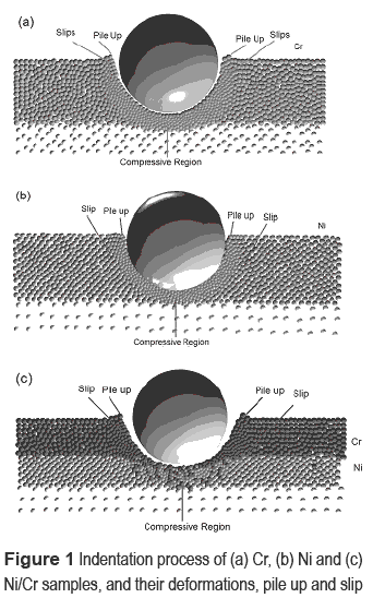
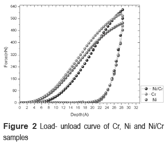
The nanoindentation processes applied to Cr, Ni and Cr/Ni for studying their mechanical properties are presented in figures 1(a), (b) and (c)) respectively. Values of force and indentation depth were obtained as shown in figure 2, in order to find the hardness and elastic modulus.
Simulations for the Cr film shows pile up around the indenter (figures 1(a)). This behavior is less appreciable in the Ni film (figures 1(b)). This pile up indicates that Cr has a higher plastic response compared with Ni, as explained by Bolshakov [15]. In both cases, a compressive region around the spherical indenter is observed, causing an increase in the applied load required for penetrating the sample. Indenter geometry influences the results of the hardness and Young's modulus [16]. This behavior is in agreement with simulations carried out in [7]. They reported the same compressive region around the indenter in thin films of aluminum grown on silicon substrates. In the case of Ni/Cr bilayers simulated in this work, the surface deformation is similar to the Cr thin film; nevertheless, a high deformation at the interface between the Cr and Ni boundary and a reduction of the compressive region are observed (figures 1(c)). This phenomenon is according to study [6]. They modeled the indentation of a Ni/Al system finding a decrease in the compressive region; moreover, the indented sample deformation is governed by slips and dislocations of the multilayer crystalline structure [6]. The plasticity of the sample refers to the recovering of the material after undergoing the effects of external forces. At the load is increased, the material recovering decreases because the load displaces the sample atoms to positions where they are forced to find equilibrium interactions that are not initially neighbor. When it happens, the material loses the initial structural information and the system plasticity decreases. On the contrary, if the force is low, the atomic displacements are lower and the original equilibrium positions are reached. For obtaining the samples hardness (H), the next equation is used:

P max is the maximum load from the unload curve (Fig. 2), Ac is the indenter contact area, corresponding to the sphere area. In this case Ac is given by:

where hc is the indentation depth. For obtaining the hardness and the system Young's modulus the Oliver-Pharr method [15] was used. In general, for any material, the elastic modulus can be calculated by using:

where Ei and Es are the indenter and sample Young's moduli and  i. and
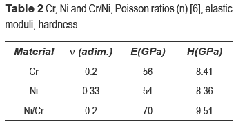
  s are the indenter and sample Poisson's ratios. These parameters are shown in Table 2.
The hardness is obtained for Cr, Ni and Ni/Cr using equations (8), (9) and results from figure 2. Values of elastic moduli and hardness are shown in table 2. Cr hardness is in agreement with the experimental results reported [17]. They carried out several experimental tests for Cr and CrN samples. In the case of the Ni thin film, the hardness is similar to that obtained by experimental results reported [18]. Regarding to the Ni/Cr system, the hardness is higher than those obtained for Cr and Ni thin films, similar to values reported in [8].
The difference between the values obtained in our simulations and the real experiments reported by Wang [18] since the molecular dynamics simulations are carried out in a nanometric scale, while experiments are in the micro-scale. this fact affects the deformation mechanisms; for instance, from the point of view of the micro-scale and polycrystalline samples, the precipitation of the grain boundaries and lattice defects are significantly higher, affecting the material behavior between 100-0.1μ. Because in this case the scale is between the 100-0.1 nm or even lower, grain boundaries and defects in the crystal structures are statistically neglected; then, in the experimental case, material deformations are strongly affected by dislocations and slips. Moreover, the assumption of a perfect lattice structure affects the simulations response compared to the experiments at the micro-scale, where there are defects in the crystal structure [19].
In this work, the stress at the interface (epitaxial stress) plays an important role in the multilayer mechanical properties, depending strongly on the interface type, crystal structure and lattice parameter. According to Sergey N, interfaces can be classified in coherent, semi-incoherent and incoherent [20]. In the first case, the type of materials involved at the interface are similar in crystalline structure and lattice parameter; in the second case, the crystalline structure is the same but the lattice parameters are different; and in the third case, both, the lattice parameter and the crystal structure are different. In our study, an incoherent interface was considered [21]. According to the literature, incoherent interfaces offer a high hardness. It is because changes in the crystalline structure can interrupt the slips propagation [21, 22].
Conclusions
Mechanical response of Cr, Ni thin films and Ni/Cr bilayers was obtained by simulations of nanoindentation using molecular dynamics. The contact behavior of the indenter modeled consists of a repulsive spherical potential. The area around the indentation presented a compressive region. This region is less visible in the bilayer because of the interface. Results show that changes in the crystal structure affect the system hardness. Moreover, Cr and Ni structures have similar parameters of cohesive energy, equilibrium radius and hardness. The presence of an interface in the bilayer can avoid the slips increasing the hardness and the mechanical performance of the system.
References
1. G. Radhakrishnan, R. Robertson, P. Adams, R. Cole.''Integrated TiC coatings for moving MEMS''. ThinSolid Films. Vol. 420. 2002. pp. 553-564. [ Links ]
2. W. Ashurst, C. Carraro, R. Maboudian, W. Frey. ''Wafer level anti-stiction coatings for MEMS''. Sensors and Actuators A. Vol. 104. 2003. pp. 213-221. [ Links ]
3. T. Fang, W. Chang, C. Weng, ''Nanoindentation and nanomachining characteristics of gold and platinum thin films''. Mater. Sci. Eng. A. Vol. 430. 2006. pp. 332-340. [ Links ]
4. T. Iizuka, A. Onoda, T. Hoshide. ''MD Simulation of Hardness Property of Al Thin Film Sputtered on Si Substrate and Its Related to Porosity''. JSME. Vol. 44. 2001. pp. 346-353. [ Links ]
5. Y. Shi, M. Falk. ''Structural transformation and localization during simulated nanoindentation of a noncrystalline metal film''. Appl. Phys. Lett. Vol. 86. 2005. pp. 011914 - 011914-3. [ Links ]
6. C. Liu, T. Fang, J. Lin. ''Atomistic simulations of hard and soft films under nanoindentation''. Mater. Sci. Eng. A. Vol. 452-453. 2007. pp. 135-141. [ Links ]
7. P. Peng, G. Liao, T Shi, Z.Tang, Y. Gao. ''Molecular dynamic simulations of nanoindentation in aluminum thin film on silicon substrate''. Appl. Surf. Sci. Vol. 256. 2010. pp. 6284-6290. [ Links ]
8. T. Fang, W. Hung. ''Molecular dynamics simulations on nanoindentation mechanisms of multilayered films''. Comput. Mater. Sci. Vol. 43. 2008. pp. 785-790. [ Links ]
9. Y. Hu, S. Sinnott. ''Constant temperature molecular dynamics simulations of energetic particle-solid collisions: comparison of temperature control methods.'' Journal of Computational Physics. Vol. 200. 2004. pp. 251-266. [ Links ]
10. C. Goringe, D. Bowler, E. Hernandes. ''Tight-binding modelling of materials''. Rep. Prog. Phys.Vol. 60. 1997. pp. 1447. [ Links ]
11. D. Christopher. Molecular Dynamics Modelling of Nanoindentation. Doctoral Thesis. Loughborough University. Loughborough, UK. 2002. [ Links ]
12. G. Ziegenhain, A. Hartmaier, H. Urbassek. ''Pair vs many-body potentials: Influence on elastic and plastic behavior in nanoindentation of fcc metals Gerolf Ziegenhain''. J. Mech. Phys. Solids. Vol. 57. 2009. pp. 1514-1526. [ Links ]
13. D. Frenkel, B. Smit. Understanding Molecular Simulation From Algorithms to Applications. 2nd ed. Ed. Academic Press. San Diego, USA. 2002. pp. 82-84. [ Links ]
14. R. Komanduria, N. Chandrasekarana, L. Ra. ''Molecular dynamics (MD) simulation of uniaxial tension of some single-crystal cubic metals at nanolevel.'' Inter. J. Mech. Sci. Vol. 43. 2001. pp. 2237-2260. [ Links ]
15. A. Bolshakov, G. Pharr. ''Influences of pile up on the measurement of mechanical properties by load and depth sensing indentation techniques.'' J. Mater. Res. Vol. 13. 1998. pp. 1049-1058. [ Links ]
16. R. Mirshams, R. Pothapragada. ''Correlation of nanoindentation measurements of nickel made using geometrically different indenter tips.'' Acta Materialia. Vol. 54. 2006. pp. 1123-1134. [ Links ]
17. H. Barankova, L. Bardos. ''Comparison of pulsed dc and rf hollow cathode depositions of Cr and CrN films''. Surf. Coat. Technol. Vol. 205. 2011. pp. 4169-4176. [ Links ]
18. C. Wang, S. Jian, J. Jan, Y. Lai, P. Yang. ''Multiscale simulation of nanoindentation on Ni (1 0 0) thin film''. Appl. Surf. Sci. Vol. 255. 2010. pp. 3240-3250. [ Links ]
19. T. Fang, C. Weng, J. Chang. ''Molecular dynamics analysis of temperature effects on nanoindentation measurement.'' Mater. Sci. Eng. Vol. 357. 2003. pp. 7-12. [ Links ]
20. S. Medyanik, S. Shao. ''Strengthening effects of coherent interfaces in nanoscale metallic bilayers.'' Comp. Mater. Sci. Vol. 45. 2009. pp. 1129-1133. [ Links ]
21. R. Hoagland , R. Kurtz, C. Henager Jr. ''Slip resistance of interfaces and the strength of metallic multilayer composites.'' Scripta Mater. Vol. 50. 2004. pp. 775-779. [ Links ]
22. Y. Cao, J. Zhang, Y. Liang, F. Yu, T. Sun. ''Mechanical and tribological properties of Ni/Al multilayers—A molecular dynamics study.'' Appl. Surf. Sci. Vol. 257. 2010. pp. 847-851. [ Links ]


