Serviços Personalizados
Journal
Artigo
Indicadores
-
 Citado por SciELO
 -
 Acessos
Links relacionados
-
 Citado por Google
 -
 Similares em
SciELO
 -
 Similares em Google
Compartilhar
Revista Facultad de Ingeniería Universidad de Antioquia
versão impressa ISSN 0120-6230
Rev.fac.ing.univ. Antioquia no.70 Medellín jan./mar. 2014
ARTÍCULO ORIGINAL
Low cost heat-and-pull rig for manufacturing adiabatic optical fiber tapers
Sistema de bajo costo para fabricar fibras ópticas adelgazadas adiabáticas
Yamile Cardona Maya*, Nelson Gómez Cardona, Pedro Ignacio Torres Trujillo
1Grupo de Fotónica y Optoelectrónica, Universidad Nacional de Colombia. AA. 050034. Medellín, Colombia.
*Autor de Correspondencia: teléfono: + 57 + 4 + 430 93 70, correo electrónico: ycardon@unal.edu.co (Y. Cardona)
(Recibido el 08 de marzo de 2013. Aceptado 05 de diciembre de 2013)
Abstract
In this paper we report the fabrication of adiabatic tapered optical fibers using a low cost heat-and-pull rig. Our setup is based on the flame-brushing technique moving in zigzag, where an inexpensive and simple portable gas micro-torch is used as heating device. Since this method does not require an electronic system to control the gas flow rate, makes out taper rig an attractive alternative, low-cost, and trivial to implement. The feasibility of such a heat source is shown with the manufacture of low-loss tapers (<0.12 dB/mm) and diameters in the micro range.
Keywords: Optical fiber, tapering, adiabaticity, sensors
Resumen
En este trabajo se reporta la fabricación de fibras ópticas adelgazadas que cumplen con el criterio de adiabaticidad, para lo cual se implementó un sistema de calor-tracción de bajo costo. Nuestra configuración se basa en la técnica de la flama que se mueve en zigzag, para esto se utilizó una micro antorcha de gas portátil de bajo costo y fácil de usar. Este sistema no requiere un control electrónico para la tasa de flujo del gas, lo que hace de nuestro sistema una alternativa atractiva, de bajo costo y trivial de implementar. La viabilidad de dicha fuente de calor se demuestra con la fabricación de fibras ópticas adelgazadas de pérdida de transmisión muy baja (<0.12 dB/mm) y diámetros en el rango de las micras.
Palabras clave: Fibra óptica, adelgazamiento, adiabaticidad, sensores
Introduction
In the past 30 years, optical fibers have found broad applications in optical communications, optical sensing, and specialty light sources [1, 2]. Advances in microtechnology and nano-technology, and the demand for improved performance, wider applications, and higher interaction density, have spurred efforts for the miniaturization of photonic devices [3]. A major step toward the miniaturization of devices is to taper optical fibers [3].
Because of their efficient confinement of the optical field as to excite nonlinear phenomena, large evanescent fields, as well as their transition regions, tapered optical fibers have attracted great interest for their potential for applications in a variety of fields: the first group includes supercontinuum generation [4], nonlinear optical devices [2], and optical trapping [5]; the second group comprises resonator and their applications [6-8], detection and manipulation of microparticles using radiation pressure, and a variety of optical sensors [8]; and the last group involves filtering and mode conversion [8].
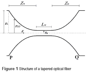
Biconical fiber tapers are generally produced from single-mode-fibers (SMFs) and consist of three contiguous regions: a waist region of minimum diameter connected to transition regions on both sides that taper into the nominal fiber diameter, see Fig 1. Controlled heating and pulling of a SMF is the most widespread method of fabricating low- loss tapers. Alternatively, fiber tapers can also be formed by chemical etching using hydrofluoric acid (HF). The fundamental difference between chemically etched tapers and heat-pulled tapers lies in the refractive index profile of the fabricated tapers [9]. While the core/cladding structure and interface are preserved in heat pulled tapers, the chemically etched tapers tend to have only the core in the waist region. Thus, the tapers may have different optical characteristics [9]. The heat- pulled fiber taper contains a small core and a thick cladding, achieving light guidance through a core/ cladding/air structure and the chemically etched taper has light guidance in the waist through a core/air structure.
The common methods of heating optical fibers for tapering are by flame [10], CO2 laser [11], electric microfurnace [12], and fusion splicer [13].
This paper reports the fabrication of adiabatic tapered optical fibers using a low cost heat-and-pull rig. By slowly thinning the fiber, the fundamental core-guided fiber mode is adiabatically converted to the fundamental taper mode, achieving fiber tapers with losses less than 0.12 dB/mm.
Materials and Method
Optical fiber taper shape
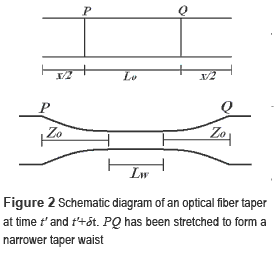
As mentioned above, the method for tapering optical fibers involves partially melting the fiber and applying tensile force to stretch and thin the fiber. The result of this process is a structure as shown in figure 1. According to this scheme, ro is the original fiber radius and rw is the radius of the narrowest part of the taper having a length Lw. Each of the transition regions have a length Z0 and its shape depends on the decreasing radius function r(z), where z is the longitudinal coordinate. The distance x corresponds to the elongation undergone by the fiber, i.e., equal to the distance  (at time t) minus the distance
  before tapering (time t=0), as shown in figure 2.
A simple model for the shape of a tapered fiber is described in detail elsewhere [10, 14], where a fixed length L0 of fiber is assumed to be uniformly heated and stretched, see figure 2, whereas outside this hot-zone the fiber is cool and solid. The radius rw is predicted to vary with taper elongation as is shown in (1).

From figure 2, comparing the length  of the tapered fiber with the initial distance
  at t=0 is easy to establish (2).

With a constant hot-zone Lw=L0, the taper transitions are always exponential in shape as is shown in (3).

In this work, this is the profile of interest because this kind of tapered fibers is widely used successfully in the fields of the applications summarized above.
Adiabatic taper
The propagation losses in optical fiber device are caused by scattering, i.e., light that is radiated from fiber core, and by coupling core modes to cladding radiation modes [15]. Scattering losses are negligible if the transition region meets the following criteria λ/nlc ≤ Z0, where λ is the wavelength in vacuum of the light signal and ncl is the refractive index of the fiber cladding. On the other hand, the modal coupling losses are negligible if Z0 ≤ Zc, where Zc=2π/ β1 – β2
 is known as the beat length. Here, β1 is the propagation constant of the fiber fundamental mode and β2 is the propagation constant of the cladding radiation mode closest to β1. Combining the above two conditions, we obtain that the length of the transition zone meets (4).

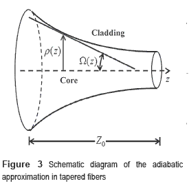
In a tapered optical fiber, the above condition is met whenever the angle Ω formed by the fiber axis and any point on the interface between the core and the cladding in the transition region is sufficiently small.
From figure 3, assuming that the transition region has a conical shape, we can be concluded that Ω r(z)/Z0. Taking (4) it becomes clear (5).

This condition is met when Z0>>r0.
Tapering setup
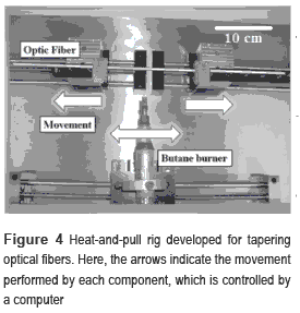
Our tapering setup is based on the flame-brushing technique and is shown in figure 4. It consists of two motors which pull the fixed fiber with a constant speed and a third motor which moves the heating device along the fiber axis, determining the shape of the resulting tapered fiber. Coating length of several cm is removed from the fiber prior to the fabrication of tapered fiber. Then the striped part of the fiber is cleaned thoroughly with acetone and isopropanol and placed horizontally on the translation stage and held by two fiber holders. The apparatus was situated on an optical table for mechanical stability, and the experiments were performed at room temperatures (22°C).
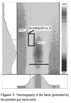
Conventionally, the heating device used in the flame-brushing technique is a sophisticated oxy-butane torch, or an oxy-hydrogen torch, which requires that the gas flow rate must be precisely regulated in order to maintain a suitable temperature. In contrast to previous reports, in this work we use a portable Butane-power micro- torch (Pro'sKit, 1PK-Gs003N) as heating device, which is inexpensive and simple to use since it does not require an electronic system to control the gas flow rate. The micro-torch ensures a narrow flame to precisely control the length of fiber to be heated and, thus, produce tapered fibers with a homogeneous waist connected to two identical decreasing taper transitions.
Figure 5 shows the optimum working position to locate the optical fiber within the flame. With a thermal imaging camera (Irisys, IRI4000), we found that in the working area the average temperature is 900°C and the maximum difference between two points is 72°C. Clearly one can observe a region relatively wide compared to the diameter of the optical fiber where the temperature is approximately constant.
Results and discussion
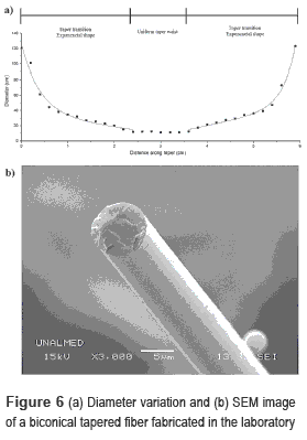
In order to test the system, several Corning SFM-28 fibers were tapered to different waist diameters. Eventually, the system can be used with other type of optical fibers by adjusting the initial parameters as shown in equation (3). As an example, figure 6(a) shows diameter variation, measured under an optical microscope (Nikon Eclipse, LV100, measurement error: 5%), of the biconical tapered fiber fabricated using the tapering rig while Fig. 6(b) shows the SEM image of the tapered fiber with a waist diameter of 2rw=5 μm. With this system were achieved adiabatic tapers up to 1 μm in diameter and 60 mm in length. As we can see, the taper shape is as expected, a 10-mm-length uniform waist and two exponentially decreasing profiles.
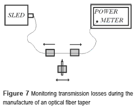
The fabricated tapers are expected to be adiabatic for light at λ=1.55 μm. Here, by using the portable gas micro-torch, we indeed easily obtain adiabatic tapers. To monitor the transmission loss of the taper during the fabrication, the emission from a SLED is injected into one end of the fiber while the other end is connected to a power meter, see figure 7.
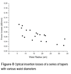
Figure 8 summarizes the optical loss to waist length of a series of tapers with varying diameters obtained using our setup. As we can see, the optical power losses were always less than 0.12 dB/mm (about 3% loss). With this result we can say that the fibers produced are adiabatic [3].
Conclusions
Tapered optical fibers offer a promising photonic platform thanks to their simple fabrication process, ultra-low loss, evanescent field and favorable characteristics for nonlinear optics. Here, we have demonstrated the fabrication of low-loss, micro-diameter biconical fiber tapers using a low cost rig based on the flame- brushing technique where a portable gas micro- torch is used as heating device. Millimeter-scale uniform waist and two exponentially decreasing profiles show the feasibility of the technique. The developed rig has the conditions to make tapers in the sub-micron range, opening the possibility of developing nanophotonic components.
References
1. E. Udd, W. Spillman. Fiber optic sensors: an introduction for engineers and scientists. 2nd ed. Ed. Wiley. New Jersey, USA. 2011. pp 9-62. [ Links ]
2. G. Agrawal. Fiber-optic communication systems. 3rd ed. Ed. Wiley. New York, USA. 2012. pp 59-67. [ Links ]
3. A. Méndez, T. Morse. Specialty optical fibers handbook. 1st ed. Ed. Academic Press, California, USA. 2007. pp. 361-396. [ Links ]
4. T. Birks, D. Bahloul, T. Man, W. Wadsworth, P. Russell. Supercontinuum generation in tapered fibres, Technical Digest. Summaries of papers presented at the Conference on Lasers and Electro-Optics. Long Beach, CA, USA. 2002. pp. 486-487. [ Links ]
5. L. Novotny, R. Bian, X. Xie, ''Theory of nanometric optical tweezers.'' Physical Review Letters. Vol. 79. 1997. pp. 645-648. [ Links ]
6. W. Henry. Use of tapered optical fibers as evanescent field sensors. SPIE's 1994 International Symposium on Optics, Imaging, and Instrumentation. San Diego, USA. 1994. pp. 2-14. [ Links ]
7. F. Xu, P. Horak, G. Brambilla. ''Optimized design of microcoil resonators.'' Journal of lightwave technology. Vol. 25. 2007. pp. 1561-1567. [ Links ]
8. G. Brambilla, F. Xu, P. Horak, Y. Jung, F. Koizumi, N. Sessions, E. Koukharenko, X. Feng, G. Murugan, J. Wilkinson. ''Optical fiber nanowires and microwires: fabrication and applications.'' Advances in Optics and Photonics. Vol. 1. 2009. pp. 107-161. [ Links ]
9. H. Haddock, P. Shankar, R. Mutharasan, ''Fabrication of biconical tapered optical fibers using hydrofluoric acid.'' Materials Science and Engineering: B. Vol. 97. 2003. pp. 87-93. [ Links ]
10. T. Birks, Y. Li. ''The shape of fiber tapers.'' Lightwave Technology Journal. Vol. 10. 1992. pp. 432-438. [ Links ]
11. J. Ward, D. OShea, B. Shortt, M. Morrissey, K. Deasy, S. Chormaic, ''Heat-and-pull rig for fiber taper fabrication.'' Review of scientific instruments. Vol. 77. 2006. pp. 083105-083105. [ Links ]
12. M. Lai, J. Franson, T. Pittman. ''Transmission degradation and preservation for tapered optical fibers in rubidium vapor.'' Appl. Opt. Vol. 52. 2012. pp. 1212-5189. [ Links ]
13. D. Yablon. Fusion Splicing of Specialty Fiber. 1st ed. Ed. Springer. Berlin, Germany. 2005. pp 27-47. [ Links ]
14. R. Kenny, T. Birks, K. Oakley. ''Control of optical fibre taper shape.'' Electronics letters. Vol. 27. 1991. pp. 1654-1656. [ Links ]
15. A. Snyder, J. Love. Optical waveguide theory. 1st ed. Ed. Springer. London, England. 1983. pp. 470-514. [ Links ]


