


Services on Demand
Journal
Article
 English (pdf)
 Article in xml format
 Article references
 Send this article by e-mail
Indicators
-
 Cited by SciELO
 -
 Access statistics
Related links
-
 Cited by Google
 -
 Similars in
SciELO
Similars in
SciELO -
 Similars in Google
Share

 Permalink
Revista Facultad de Ingeniería Universidad de Antioquia
Print version ISSN 0120-6230
Rev.fac.ing.univ. Antioquia no.71 Medellín Apr./June 2014
ARTÍCULO ORIGINAL
Influence of the boundary conditions on FE- modeling of longitudinally stiffened I-girders subjected to concentrated loads
Influencia de las condiciones de borde en el modelado por elementos finitos de vigas rigidizadas longitudinalmente sometidas a cargas concentradas
Carlos A. Graciano1,* , José Mendez2, David G. Zapata Medina1
1Dept. of Civil Engineering, National University of Colombia. Calle 59A No 63-20. Medellín 050034, Colombia.
2Dept. of Mechanical Engineering, Simón Bolívar University. Apartado 89000. Caracas 1080-A, Venezuela
*Autor de correspondencia: teléfono:: + 57 + 4 + 425 51 50, correo electrónico: cagracianog@unal.edu.co (C. Graciano)
(Recibido el 08 de agosto de 2013. Aceptado el 04 de marzo de 2014)
Abstract
Longitudinally stiffened I-girders are commonly used to build incrementally launched steel bridges. During the bridge launching, the girders are subjected to concentrated loading at the support points. These loads are generally larger than those the structure would sustain once located in its final operating position. Numerical studies have considered girder segments subjected to concentrated loading where the boundaries are simulated by kinematic constraints. It represents rigid body conditions where elements at the supported end are allowed only to rotate about an axis perpendicular to the girder web. The load is applied on the girder flange along a small length compared to the total width of the evaluated segment. This paper is aimed at investigating the validity of this hypothesis for longer lengths of the applied load. Herein, the ultimate load of a stiffened girder is determined through finite element modeling, considering the boundaries conditions in two different ways: (1) considering kinematic constraints; and (2) simulating a transverse stiffener. In addition, the used model considers the plastic behavior of the material, the existence of imperfections in the web of the girder and the effects of large deformations. The results show that for short length loadings both hypotheses yield similar results. However, as the loading length increases, significant differences in the results are observed.
Keywords:Finite element method; numerical modeling; slender girders; structural stability
Resumen
En la actualidad se utilizan vigas rigidizadas longitudinalmente en el lanzamiento de puentes mediante el método de voladizos sucesivos. Durante el lanzamiento las vigas son sometidas a cargas concentradas en los puntos de apoyo. Estas cargas son generalmente mayores a aquellas que soportaría la estructura una vez ubicada en su posición final de funcionamiento. En estudios numéricos se han analizado segmentos de vigas sometidos a cargas concentradas cuyos extremos son modelados considerando restricciones cinemáticas que simulan condiciones de cuerpo rígido. Los elementos en los bordes de la estructura son restringidos cinemáticamente permitiendo sólo la rotación con respecto a un eje perpendicular al alma de la viga. La carga se aplica sobre el ala de la viga a lo largo de una pequeña longitud en comparación con el ancho total del segmento bajo estudio. El objetivo de este trabajo es verificar la validez de dicha hipótesis para grandes longitudes de carga aplicada. La carga última de la viga rigidizada se determina mediante un análisis por elementos finitos modelando los extremos de la viga de dos maneras: (1) considerando restricciones cinemáticas, y (2) simulando un rigidizador transversal. El modelo también considera el comportamiento plástico del material, la existencia de imperfecciones en el alma de la viga y los efectos de grandes deformaciones. Los resultados muestran que para cargas aplicadas sobre longitudes cortas ambas hipótesis arrojan resultados similares, sin embargo al aumentar la longitud de carga ambos resultados divergen.
Palabras clave:Método del elemento finito; modelado numérico; vigas esbeltas; estabilidad estructural
Introduction
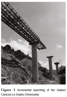
Longitudinally stiffened girders are commonly used to build incrementally launched bridges (see figure 1). The incremental launching method may often be the most reasonable way to construct a bridge over an inaccessible or environmentally protected obstacle (e.g., deep valleys or water crossings, steep slopes or poor soil conditions making equipment access difficult, and environmentally protected species or cultural resources beneath the bridge). However, the state of loading during the bridge launching is complex; there is a combination of axial loadings, bending moments and shear forces acting over the cross section of the girder, especially in the support points where concentrated loadings of great magnitude have been observed [1]. Longitudinal stiffeners are generally used to increase the bending and shear strength of the girder, mainly in the areas of concentrated loadings where the increase in resistance is required. Several researches [2, 3] have demonstrated that the ultimate strength under concentrated loadings increases as the longitudinal stiffener approaches the flange that transmits the load, with the optimum position of a longitudinal stiffener at one fifth of the girder height [4, 5].
The combination of concentrated loads and bending moment has also been investigated experimentally [6-9] showing that the inclusion of a longitudinal stiffener increases the resistance of steel girders. Numerical techniques [4, 5, 9-13] have been also employed to study the positive effect of longitudinal stiffening on the ultimate strength. In most of these studies the vertical or transverse stiffeners are replaced by kinematic boundary conditions in the numerical model. Several researchers [4, 5, 13] showed that for short loading lengths this hypothesis is valid. Others [10-12] employed structural models that assume the strain energy is absorbed only by the girder's web and upper loaded flange, yet this is only valid for small loading lengths. By increasing the loading length, the transverse stiffeners placed on the supports should absorb some of the strain energy and also act as anchor for the stress field generated in the upper zone of the girder web.
This paper presents a comparative study of the influence of the boundary conditions on the modeling of slender girders subjected to concentrated loadings. The study is performed using a nonlinear analysis via the Finite Element Method (FEM). As a calculation tool, the commercial software ANSYS [14] was employed. The numerical model employed herein takes into account the effects of large deformations, nonlinear material behavior and initial imperfections. The ultimate strength is determined considering the transverse stiffener located at the support points and compared to the one obtained by modeling kinematic restrictions. Additionally, a parametric study is carried out in order to investigate the influence of the loading length and boundary conditions on the ultimate strength of the girder. To validate the employed numerical model, the obtained results are compared with experimental tests presented by [8].
Numerical modeling via FEM
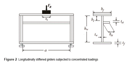
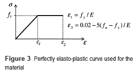
The numerical model was created using the finite element software package ANSYS [14]. Shell elements type SHELL181 were selected to model the web, flanges, transverse and longitudinal stiffeners. The SHELL181 element has 4 nodes with three translational and three rotational degrees of freedom at each node and linear interpolation is used within the element. Shell elements are typically used for plated structures where the thickness is negligible compared to its length and width. Figure 2 shows a schematic view of a longitudinally stiffened girder subjected to patch loading while table 1 lists the geometrical dimensions as well as material properties of the girders studied herein. The girders are modeled as a perfectly elasto-plastic material as shown on figure 3 with a Young's modulus, E, and a Poisson's ratio, u, equal to 210 GPa and 0.3, respectively. These girder models are also employed to study the influence of the loading length (Ss/a) on the ultimate strength of the girder and to evaluate the applicability of kinematic boundary conditions.
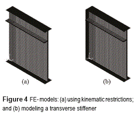
As indicated on figure 4, only half of the girder was simulated due to the existing symmetry in the applied loading, geometry and boundary conditions. Figure 4a shows a model where the degrees of freedom at the boundaries were kinematically restricted, while figure 4b illustrates a girder model including a transverse stiffener. The material and thickness for the transverse and longitudinal stiffeners were assigned the same values as to the flanges.
The concentrated load was applied via displacement control in a node located right at the center of the loading length (Ss/a). Displacements and rotations on this node were restricted in all directions except in the vertical displacement component. All nodes located in the loading length (Ss/a) move with the master node. The modified Riks method [15] was used to conduct the numerical analysis and to obtain the nonlinear load-displacement responses for each of the studied models.
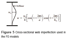
As a result of the girder manufacturing process, transport and handling, initial shape imperfections, also called geometric imperfections, arise in the girder elements [16]. Therefore, this aspect is taken into account in the finite element modeling by applying a cosine shape imperfection in the transverse direction with a magnitude (wo) of 5 mm as indicated on figure 5.
The FEM model validation was carried out in two stages. First, kinematic constraints on the boundaries were implemented; and second, a transverse stiffener at the support was included in the FEM model. A convergence analysis was then performed using a 4500-elements mesh to model the girder. Figure 6 shows the von Mises stress distribution for both cases while Table 2 lists the computed strengths.
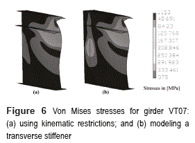
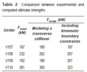
Note on table 2 that a good correlation between experimental and numerical results is observed despite the simplicity of the numerical model used in this study. In all cases, the computed strengths are closer to the experimental values when considering the transverse stiffener. For girders VT07 and VT09 the length ratio was very small (Ss/a = 0.023) while for girders VT08 and VT10 it was increased to Ss/a= 0.14. This increase may have led to a larger spread of the load into the compressed web, hence enhancing the effect of the boundary conditions since the stress field in the web will tend to attach to the transverse stiffener. The minimum difference between the strengths obtained numerically and the experimental values is obtained for girder VT07, which has a thinner flange and a smaller patch loading length. On the other hand, the maximum difference between computed and experimental strengths is about 15% and was observed for girder VT10. This bigger difference is attributable to a thicker flange and a larger patch loading length. It might be also due to discrepancies in the laboratory and FEM modeling conditions. In the laboratory, a rectangular block is used to apply the load, while in the numerical model it is applied over the entire length of the concentrated load by connecting all nodes in this region with a master node. Another factor that may have also contributed to the observed difference is the shape of the initial imperfections which are very difficult to reproduce in the numerical model.
Parametric study
The experimental study conducted by [8] varied several parameters. For instance, the ratio between flange width and thickness, and the ratio between patch loading length and the girder width. Previous numerical studies [4, 5, 9-13] achieved reasonable results by only considering short patch loading lengths. However, for larger lengths it is expected to have an influence from the vertical stiffeners located at the girder's end. This section presents a parametric analysis in which both the patch loading length and the effect of the boundary conditions are investigated. Both boundary modeling cases (kinematic constraints and transverse stiffener at the girder's end) are considered. The loading length was varied for values of Ss/a= 0.2, 0.3, 0.4, 0.5 for girders VT07 and VT 09 including a longitudinal stiffener located at b1= 0.2hw. The main difference between girders VT07 and VT09 is the thickness of theflanges as shown in Table 1.
Figures 7 and 8 present load-displacement responses for girders VT07 and VT09, respectively. Note that for all cases a larger ultimate load and smoother load-displacement curve is obtained when modeling kinematic constraint at the boundaries. It is because this modeling approach stiffens completely the girder's end, creating a structure with a higher capacity to absorb strain energy since no deformation is allowed.
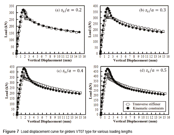
When modeling the transverse stiffener for girder VT07, the snap-through phenomenon (i.e., a reversal in the direction of out-of-plane deformation) was observed. Note on figure 7 that after reaching the ultimate load, the curves decrease sharply and return back in the direction of the x-axis. This phenomenon becomes more pronounced as the patch loading length gets smaller (e.g., Ss/a= 0.2 and 0.3). Girder VT09 also presented the snap-through phenomenon when modeling a transverse stiffener at the boundary. However, the effect was observed to be more pronounced as the loading length increases (see figure 8).
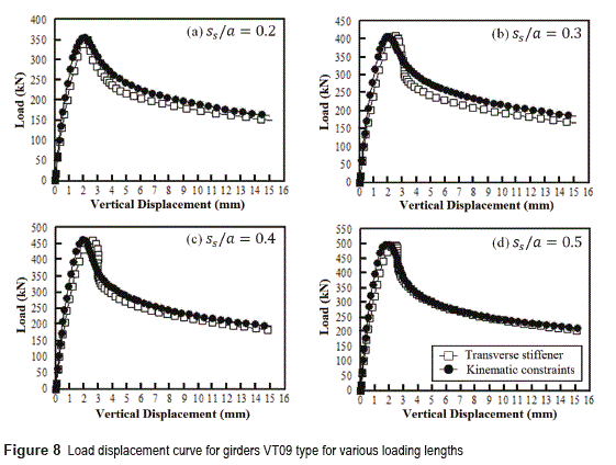
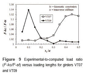
Figure 9 presents the variation in the experimental- to-computed load ratio (F-kc/F-st) with the loading length (Ss/a = 0.05, 0.1, 0.15, 0.2, 0.25, 0.3, 0.35, 0.4, 0.45, 0.5) for girders VT07 and VT09. The ultimate load ratio is calculated dividing the load obtained by including kinematic constraints with the ultimate load modeling the transverse stiffener at the boundaries. It is observed that the ratio F-kc/F-st for girder VT07 increases as the loading length increases until a value of Ss/a~0. 45, where the ultimate load difference between both modeling assumptions is about 12%. On the contrary, girder VT09 exhibits a rather unstable behavior reaching a minimum F-kc/F-st ratio for Ss/a ~ 0.3; and a maximum value at Ss/a ~ 0.1.
It must be mentioned that the findings of this parametric study can be generalized to other size specimens subjected to concentrated loadings as long as they have a slenderness ratio similar to girders VT07 and VT09.
Summary and conclusions
This paper presented nonlinear FEM analyses to study the influence of the boundary conditions on the strength of slender girders subjected to concentrated load. The effects of large deformations, nonlinear material behavior and initial shape imperfections were considered in the numerical model. Two different cases were studied: (1) modeling kinematic restrictions at the boundaries and (2) considering a transverse stiffener located at the supports. Additionally, a parametric study was performed to investigate the influence of the loading length (Ss/a) and boundary conditions on the ultimate strength of the girder. The numerical model was validated by comparing the obtained numerical results with experimental data available in the technical literature.
Based on the FEM model validation and the parametric study conducted herein, the following conclusions are drawn:
1. A better correlation between experimental and numerical results is obtained when including a transverse stiffener at the FEM model boundary rather that if one merely uses kinematic boundary constraints.
2. The snap-through phenomenon only took place when modeling the transverse stiffener.
It was not observed when including kinematic boundary constraints as the girder's end is completely stiffened with zero deformation allowed.3. The application of kinematic constraints in longitudinally stiffened girders is only valid for small patch loading lengths (Ss/a < 0.25).
4. Depending on flange thickness, which plays an important role in spreading the load on the girder web, modeling the transverse stiffener is satisfactory for larger patch loading lengths (Ss/a > 0.2).
5. The maximum difference for ultimate loads calculated based on the kinematic constraint and transverse stiffener models for girders VT07 and VT09 is about 12 and 14%, respectively.
References
1. T. Roberts, F. Shahabian. ''Ultimate Resistance of Slender Web Panels to Combined Bending, Shear and Patch Loading.'' J. Construct. Steel. Res. Vol. 57. 2001. pp. 779-90. [ Links ]
2. C. Graciano, B. Edlund. ''Nonlinear FE Analysis of Longitudinally Stiffened Girder Webs Under Patch Loading.'' J. Construct. Steel. Res. Vol. 58. 2002. pp. 1231-1245 [ Links ]
3. C. Graciano. Patch Loading-Resistance of Longitudinally Stiffened Steel Girder Webs. Ph.D. Thesis, Luleá University of Technology. Luleá, Sweden. 2002. pp. 88. [ Links ]
4. M. D'Apice, D. Fielding, P. Cooper. Static Tests on Longitudinally Stiffened Plate Girders. WRC Bulletin No 117. Welding Research Council. Shaker Heights, USA. 1966. pp. 35. [ Links ]
5. H. Evans, K. Tang. ''Longitudinal Stiffeners for Girder webs; their Behaviour and Design.'' J. Construct. Steel. Res. Vol. 6. 1986. pp. 173-97. [ Links ]
6. Y. Galea, B. Godart, I. Radouant, J. Raoul. Test of Buckling of Panels Subjected to in-Plane Patch Loading. Proc. ECCS Colloquium on Stability of Plate and Shell Structures. Ghent, Belgium. 1987. pp. 65-71. [ Links ]
7. S. Shimizu, S. Yoshida, H. Okuhara. An Experimental Study on Patch Loaded web Plates. Proc. ECCS Colloquium on Stability of Plate and Shell Structures. Ghent, Belgium. 1987. pp. 85-94. [ Links ]
8. P. Dubas, H. Tschamper. ''Stabilité des ames Soumises á une Charge Concentrée et á une Flexion Globale.'' Const. Met. Vol. 2. 1990. pp. 25-39. [ Links ]
9. M. Dogaki, Y. Nishijima, H. Yonezawa. Nonlinear Behaviour of Longitudinally Stiffened webs in Combined patch Loading and Bending. Proc. Constructional steel design World Developments. Acapulco, Mexico. 1992. pp. 141-50. [ Links ]
10. S. Shimizu, S. Horii, S. Yoshida. Behaviour of Stiffened Web Plates Subjected to the Patch Load. Proc. IUTAM symposium on Contact Loading and Local Effects in thin Walled Plated and Shell Structures. Prague, Czechoslovakia. 1990. pp. 184-91. [ Links ]
11. S. Shimizu. ''The Collapse Behaviour of WebPlates on the Launching Shoe.'' J. Construct. Steel. Res. Vol. 31. 1994. pp. 59-72. [ Links ]
12. S. Shimizu. Effect of Stiffener on the Patch Loaded Plates. Proc. 3rd International Conference on Computer Aided Assessment and Control of Localized Damage. Udine, Italy. 1994. pp. 505-12. [ Links ]
13. C. Graciano, E. Casanova. ''Ultimate Strength of Longitudinally Stiffened I-girder webs Subjected to Combined Patch Loading and Bending.'' J. Construct. Steel Res. Vol. 61. 2005. pp. 93-111. [ Links ]
14. ANSYS, Inc. Element Reference. Release 12.1. Canonsburg, USA. 2009. pp. 1688. [ Links ]
15. E. Riks. ''An incremental Approach to the Solution of Snapping and Buckling Problems.'' Int. J. Solids Struct. Vol. 15. 1979. pp. 529-551. [ Links ]
16. C. Graciano, E. Casanova, J. Martínez, J. ''Imperfection Sensitivity of Plate Girders webs Subjected to Patch Loading.'' J. Construct. Steel Res. Vol. 67. 2011. pp. 1128-1133. [ Links ]
