Services on Demand
Journal
Article
Indicators
-
 Cited by SciELO
 -
 Access statistics
Related links
-
 Cited by Google
 -
 Similars in
SciELO
 -
 Similars in Google
Share
Revista Facultad de Ingeniería Universidad de Antioquia
Print version ISSN 0120-6230
Rev.fac.ing.univ. Antioquia no.72 Medellín July/Sept. 2014
ARTÍCULO ORIGINAL
Design and implementation of an Inverse Neural Network Controller applied To VSC Converter for active and reactive Power Flow, based on regions of work
Diseño e implementación de un Controlador Neuronal Inverso aplicado a un Conversor VSC para el control de la potencia activa y potencia reactiva, basado en regiones de trabajo
José Guillermo Guarnizo Marin*, Nelson Díaz Aldana, César Trujillo, Rodríguez
1Laboratorio de Investigación en Fuentes Alternativas de Energía, Facultad de Ingeniería, Universidad Distrital Francisco José de Caldas. Carrera 7 N° 40-53, Piso 5. Bogotá, Colombia.
*Autor de correspondencia: José Guillermo Guarnizo Marín, correo electrónico: jguarnizo@udistrital.edu.co (J. Guarnizo)
(Received April 05, 2013; accepted May 06, 2014)
Abstract
Voltage Source Converter (VSC) usually used in High Voltage Direct Current (HVDC) systems, where a VSC can be used as inverter or rectifier. VSC systems allow the independent control of active or reactive power flow using different techniques. VSC systems present nonlinear behaviors, multiple inputs and multiple outputs, therefore nonlinear controllers can be used to obtain an adequate behavior. Inverse Neural Control is an alternative of an intelligent control since a mathematical model of the system is not required for designing controllers. Additionally, Inverse Neural Control can easily manage uncertainties and nonlinear behaviors typically presented in VSC systems. In this paper are presented the design, simulation and implementation of an Inverse Neural Control applied to the control of active and reactive power flow in a VSC system. Initially, is presented the simulation of the controller, where is evaluated the behavior of the system using a MIMO controller for the control of two parameters in the same time. Subsequently, the implementation of the controller is done and the e obtained is presented.
Finally, a modular Inverse Neural Network Control is proposed to overcome the drawbacks presented in the behavior of the system when it was controlled in real implementation.
Keywords:Voltage source converter, neural network, inverse neural control
Resumen
Los Convertidores de Fuente de Tensión (VSC) son usualmente usados con inversores o convertidores en sistemas de transmisión de Alta Tensión de Corriente Continua (HVDC). Una característica fundamental de los sistemas VSC es que permiten de manera independiente el control del flujo de potencia activa y reactiva por medio de diferentes técnicas de control. Los VSC presentan comportamientos no lineales y son sistemas de múltiples entradas y múltiples salidas, por lo que controladores no lineares pueden ser usados para obtener una respuesta de control adecuada. El Control Neuronal Inverso es una alternativa de control inteligente, donde no es necesario tener un modelo matemático del sistema a controlar, y a su vez es capaz de identificar incertidumbres y comportamientos no lineales, típicos en un sistema VSC. En este artículo, se presenta el diseño, simulación y posterior implementación de un Control Neuronal Inverso aplicado al control de la potencia activa y reactiva de un sistema VSC. Inicialmente, es presentado el control en simulación, donde es evaluado el comportamiento del sistema usando un controlador MIMO para el control de los dos parámetros al mismo tiempo. Posteriormente, se realiza la implementación del controlador en el sistema real y se presentan los problemas observados en la implementación. Esto conduce a la implementa un Controlador Modular Neuronal Inverso, cuyos módulos se entrenan y activan dependiendo de la región de trabajo del VSC.
Palabras clave:VSC, control neuronal inverso, redes neuronales
Introduction
High Voltage Direct Current (HVDC) systems based on Voltage Source Converters (VSC) are usually used for transmission and distribution of energy, since, in these systems the active and reactive power present some kind of flexibility from the point of view of the controllers, and consequently independent design is allowed [1]. The VSC is a power electronic converter capable to operate either as inverter or as rectifier. In the VSC the control of the active power can be done by the variation of the phase shift of the generated AC wave, with respect of the AC wave of the grid which the VSC is connected to. The control of the reactive power can be done by adjusting a factor called modulation index, which is related to the amplitude of the signal generated. Nevertheless, the behavior of the active power and the reactive power in a VSC presents nonlinear and coupled behaviors. Then, the design of classical linear controllers sometimes becomes a complex problem. In addition, analytical models of the VSC do not present an adequate representation of the behavior of the system under different conditions of operation [2]. Usually the VSC model is linearized around operating point, for example in [3] is proposes a control structure to improve the performance of high-power vector- controlled, other case is presented in [4], where the strategy proposed resorts to a model reference adaptive control plus a resonant filter based on a unique synchronous reference frame. The main problem of linearized models is once the system is outside of the operating point the controller might not work correctly.
Different nonlinear strategies of control has been implemented to control the active and reactive power flow in a VSC, for instance in [5] is presented a fuzzy controller for the active and reactive power flow in a VSC converter. Likewise, nonlinear controllers based on Lyapunov functions and small signal analysis are presented in [6] for the control of the active and reactive power in a VSC-HVDC system. Even more, a new model of the VSC-HVDC aimed at power flow solution using the Newton-Raphson method is presented in [7]. On top of that, one alternative for controlling complex or nonlinear systems is the use of Neural Networks as controllers, due to their capability of identifying the behavior of nonlinear dynamical systems, in spite of the presence of uncertainties and disturbances [8]. In this way, Inverse Neural Control is an alternative, where a Network learns the inverse dynamic of a system, for performing the control strategy [9]. In this paper is presented the simulation and hardware implementation of an Inverse Neural Control to regulate the active and reactive power flow in a grid connected VSC system.
Analysis of the grid-connected VSC
A VSC works as a synchronous machine in which its inertia of internal components are basically negligible. Therefore, it possible to perform the control of its active and reactive power almost instantaneously and independently [10].
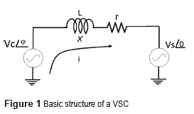
Regarding only the fundamental components of a grid-connected VSC, the basic configuration of a grid-connected VSC is presented in the figure 1, Vc is the fundamental component of the converter voltage (Van(t), Vbn(t), Vcn(t)), Vs is the fundamental component of the AC network in each phase, φ is the phase angle and this will be explained more fully later, X is the reactance of the reactor that connects the two voltage sources being L its inductance, and r is the resistance of the line that in this case will be ignored in order to simplify the analysis.
Based on the circuit of figure 1 and neglecting the losses, the active and reactive power flow (P and Q respectively) between the converter and the AC network seen from the AC network terminals are expressed in the equation (1) and the equation (2) respectively:

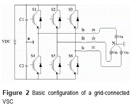
Vc(t) is basically generated by a three-phase two level inverter as shown in the figure 2. This converter topology is composed by self- commutated switches (S) (commonly IGBT) with diodes connected in anti-parallel and two capacitors C1 and C2 that have the function of energy Storage and shunt AC filters. VDC corresponds to the DC source and n is the ground reference corresponding to VDC. VSa, VSb and VsC are the fundamental components of the AC grid in each phase, la, lb and lc are the inductances of the fundamental components and ra, rb and rc correspond to the resistance of the respective line.
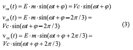
It is evident that the active power is mainly decided by φ, that is the phase angle of the fundamental component of Pulse Width Modulation (PWM) [11], with respect to the bus voltage, whereas the reactive power is mainly dependent on the magnitude of Vc. Equation (3) summarizes the sine voltage generated in each phase of the VSC, where the magnitude of Vc depends on the duty cycle (m). In this sense and based on equations (2) and (3) it would be possible to control independently the active and reactive power adjusting the values of φ,and Vc with the SPWM signal, where E= VDC/2 is the voltage in the DC side of the converter in each capacitor (C1 and C2), and ω is the angular frequency [12].The outputs voltages in each phase are:
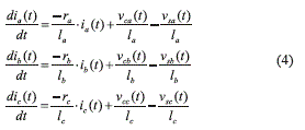
For obtaining the dynamical model of the VSC, a group of equations about the VSC can be obtained for each phase. The first group are based on laws of Kirchhoff, and they are presented in the equation (4), it is necessary to take in account the change in the phase among the three phases (a, b, c). Then, regarding Vc(t) the voltage generated by the VSC, Vs(t) the voltage at the AC network and i(t) the current in the line; and making some assumptions, (for example that the system is balanced), the sum of voltages and currents is equal to zero, because of that, the following group of differential equations can be easily found, by seeing the VSC as an inverter:
In addition, if the neutral point of the balanced load (active or passive) is not connected to the center tap of the DC voltage Vdc, the zero- sequence components of the supply will appear across the two central points (from the converter and the load), then the phase voltage referenced to the center tab of the DC source can be written in the equation (5):
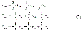
By replacing the equations (4)-(5) into (3) and expressing the formulas as an array of matrix, and by assuming that la= lb= lc=L and ra= rb = rc=R, the equation system can by written as is presented in the equation (6):
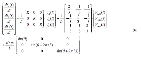
Where θ=wt+j. The equation (7) can be rewritten as is presented as follow:

Where R is the resistance matrix, A is a coefficient matrix and B is the switch function coefficient matrix [13].
When the VSC is evaluated as a rectifier only change the signs of the matrix A and B. In the model of the plant exposed above is evident that the state variables of the system are the currents, which confirms the fact that the function of the VSC is to convert the DC voltage into AC current.
To obtain the active and reactive power in the load, equations (8) y (9) can be applied in each phase.

Where (I), is the fundamental component of the line current and is the shift-phase between the voltage and current phase.
Inverse Neural Control
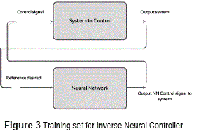
The main objective of Inverse Neural Control is to supply the desired behaviour of the actuator signal by a Neural Controller. This can be achieved by identifying the inverse dynamic of the system to control. In case of identifying dynamical systems, To obtain the active and reactive power in the load, equations (8) and (9) can be applied in each phase. Reference desired it is necessary to use a regression vector in the input and in the output patterns for the training, in order to identify dynamic behaviour [14]. For instance, in the figure 3, it can be seen that the Neural Network is trained with a signal pattern where the inputs of the Net are the output of the system to control, and the output of the Net is the control signal of the system.
Based on a NARX (Nonlinear Auto-Regressive with eXogenous input) model [15], it is possible assuming that the output of the unknown dynamic system to control at discrete time instances can be described in the equation (10):

Where t represents the discrete-time variable, y(t) is the scalar output of the system, u(t) is the scalar input of the system, y(t-1) signifies the output observed at the previous sampling time instant, n and m are the known structure orders of the system, and represent n past outputs and m past inputs, ƒ[… ] is the unknown nonlinear function to be estimated by the Neural Network [16]. The output desired for the inverse controller can be estimated by the equation (11):

Where the signal y(t), is replaced by the desired output or reference yd(t).
For any output desired u(t), the input corresponds to the regressor vector [y(t), y(t-1),…, y(t-n), u(t),…, u(t-m)], and the output obtained corresponds to û (t,w), that corresponds to the output of the Neural Controller. The input vector of the Neural Network is given, the output value measured, the Main Square Error (MSE) is found between the desired output for the corresponding input, and the obtained output, as it is shown in the equation (12):

Where NE correspond to the number of inputs- outputs patterns. Later, with this error value, the gradient descent technique and the back propagation algorithm are used to refresh weight and bias values [17], the new weight value is shown in the equation (13):

Where wR(t) correspond to actual value of weight (or bias), wR(t+1) is the actualized value of the weight (or bias), α is the training factor, and the gradient correspond to equation (14):

Where g'(n) corresponds to the inverse of the activation function of the Neural Network, and pR is the input vector of the Neural Network.
Simulations and results
In a first approximation, the VSC converter's state equations 6, 7 were used for modelling a grid connected VSC and for simulation by using Simulink of Matlab, these results are presented in [18]. The model used for a VSC is basically a merge of equations (7) to (9). As a case of study, it was proposed a 300VA converter. So the proposed VCS works in the range of active power between 100 W and -100W per phase. In this case, it is necessary to vary the phase shift between -9.5° and 9.5°. In addition for operating the VCS between 30 VAR and -30 VAR per phase, it is necessary to vary the modulation index between 0.825 and 0.925. The rage of values for 9 and m can easily be figured out by using equations (1) and (2). In particular, it is assumed a regulated DC voltage E=195V, and a linkage inductor L= 61mH.
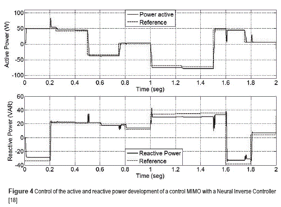
Firstly, it is designed the control of the active and reactive power with variable modulation index and variable phase shift. Instead of a MIMO controller with a Neuronal Inverse Controller, the Neural Network was trained with 3 neurons in the hidden layer; the entrance signals of the Neuronal Network are: the active power with 4 retards, the reactive power with 4 retards, the signal of error of the active power with 3 retards and the signal of error of the reactive power with 3 retards. The control signals are: The phase shift and the modulation index. The number of patterns used to train the Neural Network was 10000 patterns (10 time units per 0.001 time units for sample time), the epochs of training were 50, MSE of training converged at 4.89x10⁻⁵. In figure 4 the response of the active power control with its respective reference and the response of the reactive power control with its respective reference are shown. An adequate behavior when the references of the active and reactive power change independently can be observed, even under the presence of a disturbance which is rejected by the Neural Controller.
Hardware Implementation with Inverse Neural Controllers specialized by regions
A VSC prototype was built for experimental testing of the system. The prototype was driven by a Matlab® based virtual instrumentation tool, where the active and reactive power as well the Inverse Neural Control are worked out in real time.
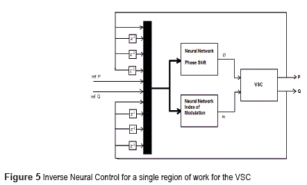
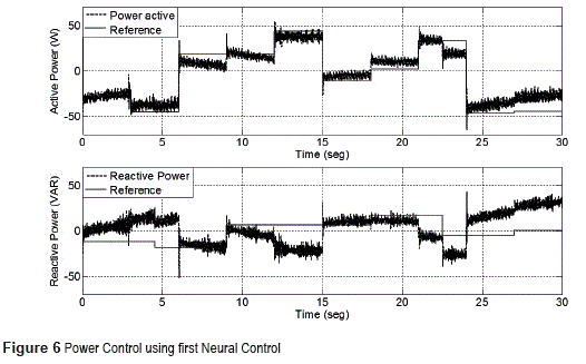
For hardware implementation an architecture is proposed for Neural Control implementation using NNARX. The data set was created by a sweep of different values of the active and reactive power of the VSC, this data set was used for training of the Neural Network. The Neural Control scheme is shown in the figure 5, where can be observed that both Neural Controllers are independent of each other, looking for obtaining a better performance in the learning of the system to control. The input signals are active power with 5 delays, error of active power with 4 delays, reactive power with 5 delays, and error of reactive power with 4 delays in both Neural Networks. The first Neural Network corresponds to the control of the phase shift, it was trained with 5 neurons in the hide layer. The second Neural Network corresponds to the control of the modulation index, it was trained by 3 neurons in the hide layer. The number of patterns used to train both Neural Networks was 10000 patterns (10 time units per 0.001 time units for sample time), the epochs of training were 150. The performance of the controllers, working together with the prototype of the VSC is presented in the figure 6.
It is observed in figure 6 that there is not regulation of the reactive power and a there is a great offset in the active power. When the data is analyzed, it was also observed that in the hardware implementation, there are two main issues which differentiate it from the simulation previously shown:
First, the constant voltage or Vdc that feeds this converter is not regulated, Then, under the process of supplying energy to the power grid, Vdc falls down, and when the converter receives power from the power grid the Vdc increases. Second, in the physical implementation it is used a resistive load at the DC side of the converter for dissipating the power which is received for the grid, in light of the above there were identified four modes of work for the prototype.
• Region 1: delivery of active power and delivery of reactive power.
• Region 2: delivery of active power and receipt of reactive power.
• Region 3: receipt of active power and delivery of reactive power.
• Region 4: receipt of active power and receipt of reactive power.
For solving this problem, in [19] is proposed the design of a series of Neural Controllers based on the identified four mode of work for the VSC. For each mode of work was obtained two Neural Networks for the control, one regulates the phase shift and other one regulates the modulation index. It should be said that in whole, there were obtained eight Neural Networks, and each has the same structure: reference of active power, active power with 3 delays, reference of reactive power, reactive power with 3 delays, for an input vector consisted of 10 inputs in whole. In each region the number of patterns used for the training of the Neural Networks was 21429 (30 units of time for 0.0014 units of time of sampling). This Neural Controller was implemented by separately modules (not interaction among the four modules) and its result is presented in [19]. The behavior of each controller in each region obtained is presented as follow:
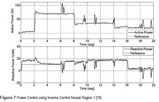
Region 1: Control of positive active power and positive reactive power (sending power to the grid and inductive behavior in the grid). The Neural Network for phase shift was trained with 5 neurons in the hidden layer, and the Neural Network for modulation index was trained with 2 neurons in the hidden layer. There were 50 times for training of the Neural Network of modulation index, the MSE of the training converges at 7.8x10⁻⁹. The performance of the system by using the obtained controllers is shown in the figure 7. Spurious pulses are observed, which are produced by external disturbances, but it is shown that the controller rejected this external disturbances and the system follows the reference.
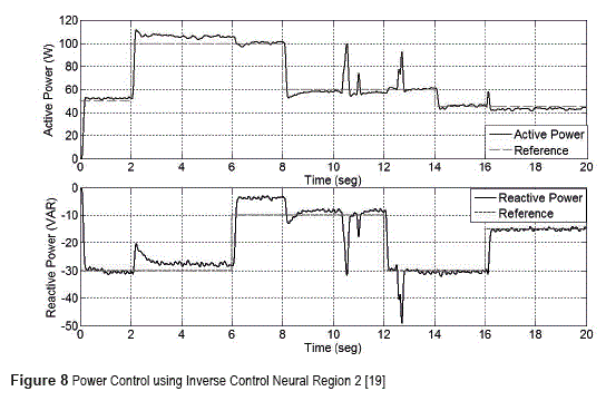
Region 2: Control of the positive active power and negative reactivate power (sending power to the grid and capacitive behavior in the grid). The Neural Network for phase shift was trained with 5 neurons in the hidden layer, and the Neural Network for modulation index was trained with 2 neurons in the hidden layer. There were 50 times for training of the Neural Network of modulation index, the MSE of the training converges at 6.7x10⁻⁷. The performance of the system, by using the obtained controllers, is shown in the figure 8, it may be is observed that the error is near to 5%, although spurious pulses are also presented in the signals controlled, as well it is possible to see that the controller takes the steady state of the VSC to the reference.
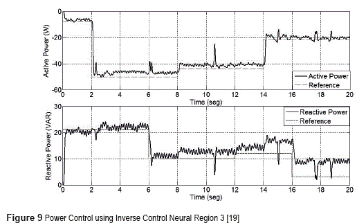
Region 3: Control of the negative active power and positive reactivate power (receiving power from the grid and inductive behavior in the grid). The Neural Network for phase shift was trained with 5 neurons in the hidden layer, and the Neural Network for modulation index was trained with 2 neurons in the hidden layer. There were 50 times for training of the Neural Network of modulation index, the MSE of the training converges at 2.3x10⁻⁷. The performance of the system by using the obtained controllers is shown in the figure 9. In this case steady-state error is presented in some work areas, in other areas it is working appropriately. The signals controlled are noisy since the resistive load is placed for the dissipation of the received active power, spurious pulses of the fluctuations of the net are observed too.
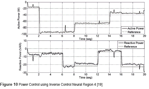
Region 4: Control of the negative active power and negative reactive power (receiving power from the grid and capacitive behavior in the grid). The Neural Network for phase shift was trained with 5 neurons in the hidden layer, and the Neural Network for modulation index was trained with 2 neurons in the hidden layer. There were 50 times for training of the Neural Network of modulation index again, the MSE of the training converges at 1.1x10⁻⁹. The performance of the system by using the obtained controllers is shown in figure 10. This one seems to be the best controller that presents the best error in steady-state in an entire sweeping of powers they don't overcome 3%. Similarly to the previous one, the signals of power are noisy due to the load that it is placed to dissipate power.
Connection of four Neural Controllers and hardware implementation
Although in last section the results of the implementation of Neural Controllers proposed were presented, showing an adequate performance in the signals of the active and reactive power flow of the VSC, these results correspond to experiments in each controller to its respective region of work, and not commuting between regions were presented.
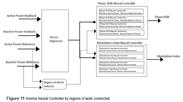
However for a complete control of VSC, it is necessary to connect four controllers and evaluate the performance of the power signals to control. For this, the complete Inverse Neural Controller is connected in a composed system by a common regression vector, one selector which actives the respective Neural Controller depending on the region of work, and 8 Neural Controllers, 4 for phase shift and 4 for modulation index. One scheme is presented in the figure 11.
The selector as well as the Neural Controller including the vector regressor were implemented using Simulink of Matlab. This selector is composed by 2 comparators to decide if the active power is positive or negative, and the other two decide if the reactive power is positive or negative. 4 AND gates determine which region of work is working. The signal of the selector goes to two Neural Controllers selected depending of the region of work of the reference, determining phase shift and index modulation of VSC.
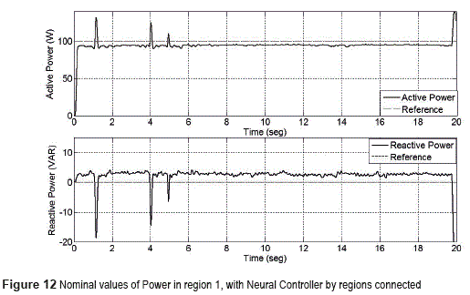
New experimental results were carried out to determinate the behaviour of the Inverse Neural Controller connected by the selector. For the region 1 the signals obtained for the nominal values are presented in the figure 12. The active power was obtained 97 W presenting an error of steady-state error of 3%. The reactive power obtained was 3 VAR with a reference of 0. Traditional spurious pulses and noise appear in the signals of power.
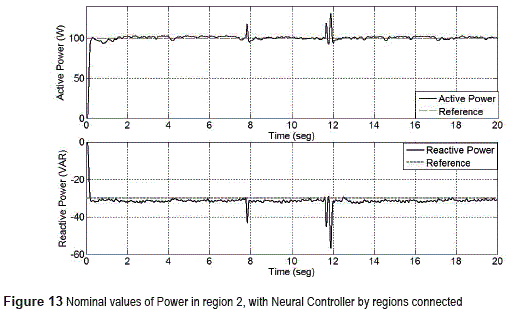
For the region 2 the active power was 100 W and the reactive power follows -30 VAR, with no steady-state errors but noisy and spurious pulses presented always in the network, as is shown in the figure 13.
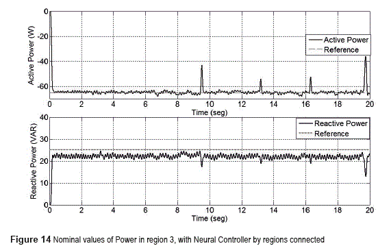
For region 3 was obtained an active power value of -64 W and reactive power of 23 VAR, with a steady-state error of 8%. These signals are presented in figure 14.
For region 4 was obtained -100 W for active power and -300 VAR in reactive power, showing -10% of steady-state error.
These results show that is more difficult to delivery reactive power, due to the VSC did not find the nominal value. That means that from the side to VSC, the converter operation has a capacitive characteristic better than inductive.
Conclusions
An advantage of using Neural Networks as a controller is working directly on the system, by which the time variations of this one are guarded in the information of the training. In addition, these behaviors are taken into account at the moment of doing the control action, improving the control performance. Other additional advantage is that with strategy it is not needed mathematical model for the design ofthe controller. Particularly, VSCs converters offer more flexibility in the control of active and reactive power flow, in comparison with any other topology, used for HVDC system. Because of that, Inverse Neural Control was proposed as an alternative in this paper for being used in VSC-HVDC system.
In some nonlinear systems such as VSC converters, traditional Inverse Neural Controller cannot identify completely the dynamics of the system due to its complexity, thus the control shown low performance. One alternative proposed is to specialize controllers by regions of work, training a Neural Controller by different zones where the behavior to the system is not much different, allowing a better performance. These specialized Neural Controllers are commuted by a selector which identifies the region of work and selects the appropriated Controller, showing an appropriated behavior for the control of active and reactive power flow in the VSC.
References
1. J. Beerten, R. Belmans. ''Modeling and Control of Multi-Terminal VSC HVDC Systems''. Energy Procedia. Vol. 24. 2012. pp. 123-130. [ Links ]
2. C. Trujillo, D. Velasco, J. Guarnizo, N. Díaz. ''Design and implementation of a VSC for interconnection with power grids, using the method of identification the system through state space for the calculation of controllers''. Applied Energy. Vol. 9. 2011. pp. 3169-3175. [ Links ]
3. B. Parkhideh, S. Bhattacharya. ''Vector-Controlled Voltage-Source-Converter-Based Transmission Under Grid Disturbances''. IEEE Transactions on Power Electronics. Vol. 28. 2013. pp. 661-672. [ Links ]
4. A. Leon, J. Mauricio, J. Solsona, A. Gómez. ''Adaptive Control Strategy for VSC-Based Systems Under Unbalanced Network Conditions''. IEEE Transactions on Smart Grid. Vol. 1. 2010. pp. 311-319. [ Links ]
5. N. Díaz, C. Trujillo, J. Guarnizo. ''Active and reactive power flow regulation for a grid connected vsc based on fuzzy controllers''. Revista de la Facultad de Ingeniería Universidad de Antioquia. N.° 66. 2013. pp. 118-130. [ Links ]
6. H. Latorre, M. Ghandhari, L. Soder. ''Active and reactive power control of a VSC-HVdc''. Electric Power Systems Research. Vol. 78. 2008. pp. 1756-1763. [ Links ]
7. E. Acha, B. Kazemtabrizi, L. Castro. ''A New VSC- HVDC Model for Power Flows Using the Newton- Raphson Method''. IEEE Transactions on Power Systems. Vol. 28. 2013. pp. 2602-2612. [ Links ]
8. N. Sadegh. ''A perceptron network for functional identification and control of nonlinear systems''. IEEE Transactions on Neural Networks. Vol. 4. 1993. pp. 982-988. [ Links ]
9. M. Norgaard, O. Ravn, N. Poulsen. ''NNSYSID and NNCTRL tools for system identification and control with neural networks''. Computing & Control Engineering Journal. Vol. 12. 2001. pp. 29-36. [ Links ]
10. M. Kalantar, S. Mousavi. ''Dynamic behavior of a stand-alone hybrid power generation system of wind turbine, microturbine, solar array and battery storage''. Applied Energy. Vol. 87. 2010. pp. 3051-3064. [ Links ]
11. E. Mamarelis, C. Ramos, G. Petrone, G. Spagnuolo, M. Vitelli, R. Giral. ''Reducing the hardware requirements in FPGA based controllers: a photovoltaic application,'' Revista Facultad de Ingeniería Universidad de Antioquia. N.° 68. 2013. pp. 75-87. [ Links ]
12. A. Morahana, P. Dash. ''Input-Output Linearization and Robust Sliding-Mode Controller for the VSC- HVDC Transmission Link''. IEEE Transactions on Power Delivery. Vol. 25. 2010. pp. 1952-1961. [ Links ]
13. L. Haifeng, L. Gengyin, L. Guangkai, L. Peng, Y. Ming. Analysis and Design of Hinf Controller in VSC HVDC Systems. Proceedings of the Asia and pacific IEEE/PES. 2005. pp. 1-6. [ Links ]
14. J. Guarnizo, C. Trujillo, J. Lopez, J. Soriano. ''Identificación de Reductores de Tensión Conmutados con Realimentación de Variables de Estado utilizando Redes Neuronales''. Ingenium. Vol. 20. 2009 pp. 46-53. [ Links ]
15. L. Aguirre, M. Correa, C. Cassini. ''Nonlinearities in NARX polynomial models: representation and estimation''. Control Theory and Applications, IEE Proceedings. Vol. 149. 2002. pp. 343-348. [ Links ]
16. M. Norgaard, O. Ravn, N. Poulsen, L. Hansen. Neural Networks for Modelling and Control of Dynamic Systems: A Practitioner's Handbook. 3rd ed. Ed. Springer. London, Great Britain. 2003. pp. 126. [ Links ]
17. S. Haykin. Neural Networks: A Comprehensive Foundation. 2nd ed. Ed. Prentice Hall International. Hamilton, Canadá. 1999. pp. 183-198. [ Links ]
18. F. Forero, A. Molina, J. Guarnizo. Design of a Controller Inverse neural Applied to a Converter VSC for the Control of the Active and Reactive Power Flow. Proceedings of the (INTERCON) XIV Congreso Internacional de Ingenierías Eléctrica, Electrónica y Sistemas. Trujillo, Peru. 2008. pp. 213-221. [ Links ]
19. A. Molina, F. Forero, J. Guarnizo, H. Chamorro. Implementation of Inverse Neural Control To VSC Converter for Active and Reactive Power Flow. Proceedings of the ISAP '09. 15th International Conference Intelligent System Applications to Power Systems. Curitiba, Brazil. 2009. pp. 1-6. [ Links ]


