


Services on Demand
Journal
Article
 English (pdf)
 Article in xml format
 Article references
 Send this article by e-mail
Indicators
-
 Cited by SciELO
 -
 Access statistics
Related links
-
 Cited by Google
 -
 Similars in
SciELO
Similars in
SciELO -
 Similars in Google
Share

 Permalink
Revista Facultad de Ingeniería Universidad de Antioquia
Print version ISSN 0120-6230
Rev.fac.ing.univ. Antioquia no.72 Medellín July/Sept. 2014
ARTÍCULO ORIGINAL
Transduction methods used on biosensors: amperometry and fluorescence
Métodos de transducción usados en biosensores: amperometría y fluorescencia
Juan Bernardo Cano1*, Katia Buonasera2, Gianni Pezzotti3
1Research Group on Efficient use of Energy (GIMEL), Department of Electrical Engineering, Engineering Faculty, Universidad de Antioquia. Calle 70 N.° 52-21. AA. 1226. Medellín, Colombia.
2Institute of Crystallography, Italian National Research Council IC-CNR. Area della Ricerca di Roma 1. Via Salaria Km 29.300. CAP 00010. Montelibretti (Rome), Italy.
3Project Engineer at Biosensor SRL. Via degli Olmetti 44. CAP 00060. Formello (Rome), Italy.
*Autor de correspondencia: teléfono:: + 57 4 2198558 , correo electrónico: : jbcano@gmail.com (J. Cano)
(Received August 28, 2013; accepted May 16, 2014)
Abstract
Biosensor devices have applications in a variety of fields as environmental analysis, biomedical, bio-defense, food and agriculture. On this kind of sensors, a biological material (known as biomediator) reacts with target analytes and an appropriated transduction system converts that reaction to an electrical signal that can be processed, saved and transmitted by using electronic systems. In this article, two transduction methods used for biosensing applications are described: amperometry that is based on the measurement of the electron transfer occurring inside the biomediator and fluorescence, that is based on the measurement of the re-emitted light. Emphasis has been done on the electronics design, including component selection, useful circuit topologies and common problems and solutions. Electronics has been validated for the development of biosensor-based instruments characterized by low production costs and portability.
Keywords:Biosensors, amperometry, fluorescence, transduction methods, electronic design
Resumen
Los biosensores tienen aplicación en una gran variedad de campos, incluyendo el análisis ambiental, biomedicina, biodefensa, alimentación y agricultura, entre otros. En este tipo de sensores, un material biológico (conocido como biomediador) reacciona con el analito y un sistema de transducción apropiado transforma dicha reacción en una señal eléctrica que puede ser procesada, almacenada o transmitida usando sistemas electrónicos. En este artículo, se describen dos métodos de transducción usados en aplicaciones bio-sensoriales: la amperometria que consiste en la medida del transferimento electrónico (corriente) del biomediador y fluorescencia que es basada en la medida de la luz re-emitida. Se enfatiza en el diseño electrónico (selección de componentes, topologia de los circuitos, problemas comunes y soluciones). Estos diseños han sido utilizados en el desarrollo de instrumentos comerciales para biosensores, caracterizados por bajos costes de producción y portabilidad.
Palabras Clave:Biosensores, amperometria, fluorescencia, métodos de transducción, diseño electrónico
Introduction
Bio-sensors devices use a biological recognition element known as bio-mediator. This biomediator can be composed by isolated enzymes, immunosystems (antibodies), tissues, cells or cell organelles capable to produce an output signal in response to a biochemical variation caused by particular environmental, chemical, or physical conditions [1].
Biomediator's output signal can be of different types. Some biomediators produce an optical signal (fluorescence, chemiluminescence), others change their mass or their electrical properties (voltage, current, impedance), or produce temperature or pH changes. The output signal must be converted by a suitable transducer into an electrical signal that can be easily processed, registered or transmitted by an electronic system.
Bio-sensors application includes different fields, such as environmental protection, medical analysis, alimentary and safety, and are becoming commercial realities in applications where low cost and ease of use are important [2]. This article focuses on two types of biosensors: those based on amperometry and those based on fluorescence detection.
Amperometric biosensors are very often found on literature. Glucose sensor for diabetes control (using an enzyme as bio-mediator) is the most known biosensor of this type [1]. Amperometric sensors has been also proposed for herbicide detection on water by using enzymes [3] or photosynthetic material (algae) [4, 5].
Fluorescence markers are used on DNA-based biosensors [6], or to detect the enzyme activity. Sometimes auto-fluorescent substances are also used on fluorescence biosensors, as is the case of photosynthetic organisms [4] and some bacteria [5].
The two transduction systems here investigated are described focusing on electronics. The two systems were used on the development of real, commercial biosensor instruments, characterized by low production cost, small size and portability.
Amperometric transduction
Amperometric detection consists on the measurement of current generated by the reduction/oxidation processes of electro-active substances in intimate contact with an electrode system. In order to allow this processes to happens, an appropriated potential must be set between the electrodes, and the correct potential depends on the characteristics of the reaction occurring and the electrode's materials.
Two types of configurations are commonly used in amperometry for the electrodes: two and three electrodes systems. A two electrodes system is composed by a reference (RE) and a working (WE) electrode, and, in this case, the current is measured on the working electrode (Irw) whereas the potential is set between working and reference electrodes (Vrw) (Figure 1, up).
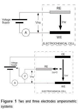
This configuration has problems on potential stability. The current flowing through the reference electrode leads to ohmic voltage drops and material polarization problems. To overcome those issues, the three electrodes configuration is commonly used (Figure 1, down).
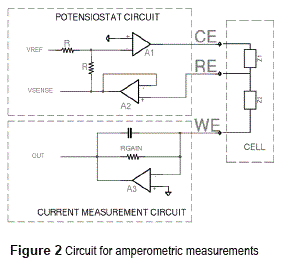
On three electrodes systems, an auxiliary electrode (also known as counter electrode, CE) is used. The current will flow between the counter and working electrodes (Icw), while the reference electrode circuit presents a high impedance to block the current flow (Ire=0). To set the reference electrode potential a special control circuit is necessary (potensiostat circuit on Figure 2).
The electrodes systems for biosensors are normally implemented on screen-printed electrodes (S.P.E) [7]. These are built by the deposition of different ''ink'' layers over a PVC, ceramics or aluminum base. There are one or more layers of electrical conductive surfaces for electrodes conformation and a contact line for external electronics interface. S.P.E's main advantages are low cost (intended to be disposable), easy automated production and small size.
Figure 2 shows the electronics circuit implemented for amperometric detection on three electrodes S.P.E. This circuit is discussed on the next paragraphs.
Current Measurement
The current measurement circuit for the working electrode has been implemented by using an operational amplifier on transconductance amplifier configuration (Figure 2, down, A3 amplifier). This configuration guarantees a potential near to zero on the working electrode (affected only by the operational amplifier input offset voltage and finite gain) that is important for precision of electrochemical potential (Vrw) [8].
Considering that the input current on to the amplifier inputs is zero, the measurement current travels through the RGAIN resistor, giving an output voltage of minus RGAIN times measurement current. A feedback capacitor, in parallel with RGAIN is necessary for stability reasons (especially if large gains are desired) and forms a single pole low pass filter.
In biosensor applications, the intensities are normally in the range of some nano-ampere up to tenths of micro-ampere. These low currents require special considerations to obtain accurate measurements:
#8226; The operational amplifier must be characterized by low input bias current (Ibias), this bias is subtracted (or added depending on his sign) from the WE current before being amplified, becoming an important error source. By this, F.E.T (field effect transistor) based amplifiers are recommended for this type of applications. It's also important to control the Ibias variation with temperature when choosing the right amplifier.
#8226; As already discussed, low input offset amplifiers are required. The electrochemical potential can be low as few tents of millivolts for some applications. By this amplifiers with input offset lower than one millivolt or with an offset adjustment mechanism are recommended.
#8226; Special attention must be taken on the printed circuit board (P.C.B) layout. Current losses trough board isolation are possible if ''high'' voltage signals crosses near to the amplifier input (depending on measurement range, isolation between signals and distance is possible to have considerable losses with voltages as low as five volts). Use of guard rings is recommended. Proper P.C.B distribution is necessary, digital and switching signals must be keep away from low current signals. Supply line decoupling, star ground and ground planes are important [9, 10].
• Residues of soldering process can lead to current losses, appropriated cleaning is advised [8].
#8226; Induced noise from AC power and other electromagnetic devices is always present. Shorter cable (and PCB tracks) length and proper cable shielding (in some cases even amplifier shielding) helps to mitigate this.
Potensiostat
Potensiostat circuit must keep the required reference potential on three electrodes systems (Fig, upper, A1 and A2 amplifiers) [11]. The potensiostat circuit uses the high input impedance of operational amplifier (A2 on figure 2) to block the current flow through the reference electrode. The A2 amplifier is configured as voltage follower and his output can be used to monitor the actual status of the reference potential (Vsense signal).
The Vref input is used for setting the desired reference potential (from a digital to analog converter). If the A1 amplifier is on his linear region (possible only if exists a feedback path between RE and CE electrodes -Z1-, due to the chemical substances on contact with the electrodes) is possible to demonstrate that the voltage on RE electrode is kept equal (with opposite sign) to the Vref signal.
Proper potensiostat operation strongly depends on the conditions of the substances on contact with the electrodes (on Figure 2 modeled as Z1 and Z2 impedances). A poor conductivity between CE and RE or/and an excessive WE current will require a higher CE to RE voltage and can put the A1 amplifier on saturation condition. Also amplifiers stability is not guaranteed because feedback impedances are unknown. By this a constant monitoring is necessary on Vsense signal, warning the user when the potensiostat is out of operation in order to modify the analysis conditions.
Considerations done for current measurement are also applicable to this circuit. The RE electrode signal is particularly sensible to coupled noise due to the higher input impedance, by this additional shielding on this signal is recommended.
System Integration
Development of an integrated, low cost, portable instrument for amperometric detection has taken as basis the circuits described on Current Measurement and Potensiostat.
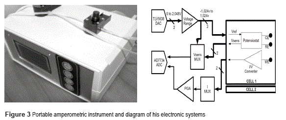
A digital to analog converter has been used to generate the voltage reference for the potensiostat circuit. This converter can be configured (by the central processing unit) to generate a constant DC voltage (necessary on current vs time analysis -chronoamperometry-) or a different waveform (by example a triangle waveform used on cyclical voltammetry analysis). This converter has 12 bits resolution and a conversion rate of up to 1M samples/second.
Instead, an analog to digital converter is used to sample the Vsense signal and the output of the current amplifier. This converter is 16 bits resolution and up to 64ksample/s (Figure 3).
Finally, the control and data processing is carried out by an 8-bit Atmel microcontroller (C51 family). A friendly user interface -trough graphical LCD and keyboard- and a PC communications interface were also provided. The interconnection of the different electronic systems is shown on figure 3.
From a mechanical point of view, the instrument consist in two measurement cells, each one with space for S.P.E insertion and flow lines for sample and measurement buffers. The cells are also provided with light sources (Light Emitting Diodes, LEDs at 670nm and 470nm wavelengths) for stimulation of photo-sensible materials.
Transduction system validation
Validation of the potensiostat and current measurement circuits was conducted by connecting these to a dummy load circuit (Figure 2). This circuit guarantees the feedback path necessary for proper potensiostat operation. It consists of two impedances: Z1 connected between CE and RE and Z2 connected between RE and WE. Z1 is a resistor in parallel with a capacitor (capacitance is necessary for stability reasons) while Z2 is pure resistive.
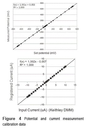
Validation of the potensiostat circuit was done by setting -on the user interface menus- a desired potential and measuring the true voltage between the reference and working electrodes. That measurement was conducted using a Keithley 2700 Digital Multimeter (DMM)/data acquisition system. Figure 4 (up) shows the data points obtained and his linear regression. Offset and gain calibration factors were software implemented on the instrument to diminish the effect of electronics tolerances.
Validation was also conducted on current measurement. To do this, Z2 was replaced by a variable resistor (in order to vary the working electrode current while maintaining a constant reference electrode potential) and the current was measured using the Keithley DMM (in series with the working electrode) and the instrument itself. Figure 4 (Down) shows the plot of the obtained data, with the measurement of Keithley DMM on X axis and instrument on Y axis.
Linearity and accuracy shown on instrument potential and current allows using it on real sample measurements, as illustrated on next paragraphs.
Real sample instrument validation
Instrument operation was validated using photosynthetic bio-mediators immobilized on screen printed electrodes, an unicellular green algae (Chlamidomonas reinhardtii) was used [12].
Operation whit this type of bio-mediator is based on successive dark/light periods. During the dark period the biological material enters on relaxation status, after that it's stimulated by a light pulse producing an electronic transport due to the photosynthesis process. This process is repeated cyclically.
In the dark period exists a constant ''base line'' current on the working electrode. During the light time, the current rises to a peak value and then decreases until returning to the base line level when the light is turned off. That light- induced current peak depends on photosynthesis efficiency and if an external factor (by example a photosynthesis blocking herbicide) is stressing the bio-mediator the current peak will be lower.
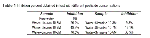
Thus, measuring the magnitude of the current peak (peak minus baseline) when the bio-mediator is in non stress conditions (Ibuffer) and when is in contact with a sample (Isample), then calculating the inhibition percentage (Eq. 1) is possible to obtain an estimate of herbicide presence on sample [12].
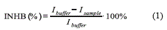
Tests consisted on a mutant of C. reindartii algae exposed to different concentrations of linuron and simazine herbicides [4]. Results are shown on the table 1; it shows how the inhibition percentage increases with herbicide concentration as expected.
Fluorescence
A fluorescent element absorbs light form an external source and re-emits part of it. The re-emitted light has a longer wavelength tan excitation light. Different elements are fundamental on a fluorescence measurement system:
Excitation light source: This element must generate light of appropriated intensity and wavelength in order to stimulate the fluorescence process. It's important that the light intensity be as constant as possible and (for some applications) fast turn-on times are desired.
Optical filter: A long-pass filter is put above of the light measuring element. It must block light of lower wavelengths (the excitation light) while allows to pass light of higher wavelengths (the fluorescent material's emitted light).
Detector: This is the transduction element that converts the incident light on an electrical variable.
Cell body: A suitable cell body must isolate the material under measurement of the environmental lights interference (non necessary on pulsed fluorescence applications [13]). Also sample loading / unloading mechanisms (as micro-fluid systems) are necessary.
The parameters of interest on fluoresce measurements can vary depending on application. On some application the interest is only on the presence / absence of fluorescence, in others the steady state or final value [14], sometimes is necessary to capture the entire fluorescence transient from start to end of the light pulse [15].
Fluorescence Transduction
Light measurement on fluorescence applications requires a careful selection of detector device and design of associated electronics.
Different types of photodiodes (conventional, avalanche (APD), PIN ), photo-transistors and photo-multiplier tubes are valid options as light transducers. Selection with depend on allowed fabrication costs, size and required response speed and sensitivity of the system.
Photo-multiplier tubes (PMTs) provides a very high sensitivity, internal gain, low noise and fast response, but his main drawbacks are high cost, large size and specific operational conditions (high voltage bias, sensibility to magnetic and electric fields, requires special handling considerations). By this are more suitable for high precision laboratory applications than for low cost portable applications.
Avalanche Photo-diode has also an excellent sensitivity and internal gain but requires a high voltage supply. Conventional photo-diodes (PN and PIN types) doesn't have such larger sensitivity and don't provides internal gain, but are easy to operate with low voltage supplies, are low cost and small size making them ideal for portable equipment.
Photo-diodes acts by converting incident light on current. The transfer relationship (sensitivity: amperes per watt of incident light) depends on light wavelength. During design, the emission wavelength of the bio-mediator must be taken into account for the selection of the right photo-diode.
Photo-diode response speed is an important factor on applications where interest is on fluorescence transient. On this cases use of PIN photo-diodes is recommended. Speed depends on internal diode capacitance that can be further reduced by using a reverse bias [16].
Figure 5 shows a circuit used for photo-diode conditioning based on an operational amplifier in trans-resistance configuration. This configuration has already been discussed on Current Measurement title.
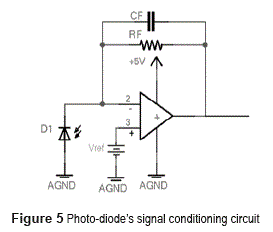
The Vref voltage supply function provides a reverse bias on the photo-diode, given the fact that the voltage on the inverting and not inverting inputs of the operational amplifier are the same while on linear operation. Reverse bias is mandatory when using PIN type photo-diodes.
Stability is a critical issue on figure 6's circuit. Photo-diode internal capacitance acts on the inverter input of the operational amplifier and is a potential source of instability. Stability analysis must take into account the dynamic properties of the operational amplifier (normally modeled as a one pole low pass system) the feedback path (Rf and Cf) and the photo-diode capacitance [17].
High values of feedback capacitance helps to stabilize the system, but decreases the bandwidth producing slower responses. This is an issue on transient fluorescence analysis. Figure 6 shows PSPICE simulation results for the figure 5 circuit. It shows the transient response at a photo-diode current step (ie: a light suddenly turning on) at time 1 ms. Simulation has been built using LTC6081 operational amplifier model from Texas Instruments, a gain of one million (IMohm), and a feedback capacitance varying from 1pF to 15 pF. The photo-diode simulated was the Osram BPW34 which model was built using data-sheet information.
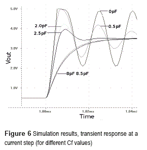
Simulation confirms critical importance of feedback capacitance on stability and response time. At lower values of Cf the system is near to instability and tends to oscillate showing also a considerable over-peak, at higher values the system response is slower but over-peak is not present.
System integration
Circuit described on previously had been implemented on a multi-cell instrument for transient fluorescence detection (Figure 7) [18].
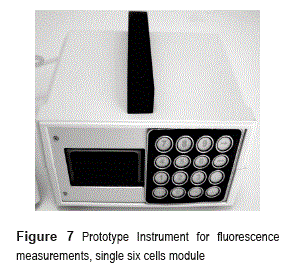
This instrument is composed by up to four modules of six cells each. Each cell uses four leds as excitation light sources (red led 660nm) and the optical filters are set for fluorescence detection at the 730nm spectral range. Target biomediators are photosynthetic as explained on next paragraph.
The photo-diode conditioning circuits (one by each cell) are connected at a multiplexing system in charge of measurement cell selection. The multiplexers output feeds (trough appropriated ADC drivers) the input of a high speed / high resolution analog to digital converter (up to 1MSPS and 16 bits).
Also, controlled current, programmable led drivers are used to manage the excitation light intensity. A SD memory card allows results data saving. An USB communications port allows PC control and a user interface is available through a graphical LCD and alphanumerical keyboard. The instrument control is on charge of a 32 bits microcontroller, STMicroelectronics STM32 series, ARM CortexM3 core. This microcontroller provides enough computing power for fast data acquisition and real time data compression.
Instrument validation
Instrument has been validated on applications with photosynthetic bio-mediators. Transient fluorescence on photosynthetic materials is also known as Kautsky curve [19] .
When this type of material is left on darkness by a given period of time (dark adaptation) and then suddenly exposed to a light, a fluorescence emission begins. Fluorescence (Figure 8) quickly increases to an initial level (named F0, stable after some nanoseconds of light pulse) and then begins a multi step rise (with different intermediate plateau named Fi, FJ, Fk) until arriving at a maximum level (Fm) and then begins to decrease [19].
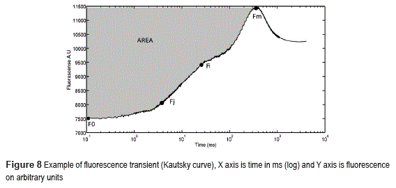
This transient fluorescence is due to a series of electron transfer process internal at the chloroplasts (tilakoid membrane). When the bio-mediator is on contact with a photosynthesis blocking substance (by example some types of herbicides) the shape of this transient is changed.
The fluorescence instrument has been tested by measuring the fluorescence transient of C. reinhardtii algae. These measurements were conducted after fifteen minutes of dark adaptation period, using the maximum light intensity possible by the instrument (aprox. 550Umol/m2/s2). The algae were in solution in a volume of 500uL, Optical Density (OD) = 1. Measurements where done with and without presence of Linuron pesticide.
Figure 9 (left) shows results. The flourescence curves (measured on arbitrary units) where normalized by subtracting the F0 level and dividing by the Fm level.
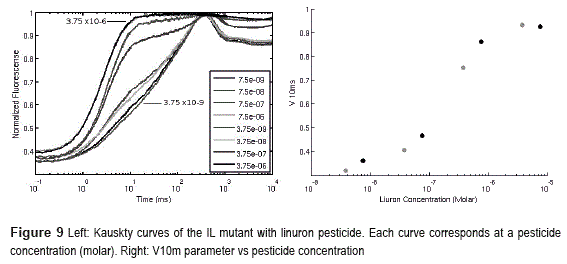
Is evident the change (increase) on the fluorescence levels near 10ms when the bio-mediator is exposed to increasing concentrations of Linuron pesticide. This change can be quantified by defining a parameter (V10m, Equation 2). It depends on the fluorescence intensity at 10ms (F10ms), the initial fluorescence (F0) and the maximum fluorescence (Fm).
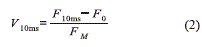
Figure 9 (right) shows the evolution of the V10 value vs concentration of pesticide using data from the previously described tests. Notice how the parameter increases with the pesticide concentration following a sigmoid shape as expected.
Conclusions
Biosensors are becoming commercial realities on applications where low costs, easy to do, on site measurements are required. This is the case on environmental monitoring applications.
Many biosensor applications are based on fluorescence or amperometry transduction. The electronic systems required for these techniques can be implemented using commercial electronics, making them suitable for applications on developing countries. However is necessary to take into account the design problems related at working with low level and or fast changing signals.
The instruments that have been developed were capable of detecting the biomediator response during testing. This demonstrates the correct design and implementation of the transduction stages. Is important to notice that the use of different biomediators can lead to more exigent design parameters.
Photosynthetic biomediators (as the ones used on instrument testing) produces responses for both types of transduction methods (fluorescence and amperometry). This creates interest on the development of multi-transduction instruments that can measure contemporary these two variables in order to obtain complementary data to improve analyte estimations.
Acknowledgements
This work has been supported by Cristallography Institute of Italian National Research Council IC- CNR (Rome Italy) and Biosensor SRL (Italy), trough the FP7 BEEP-C-EN European project. The authors wish also to thank to the University of Antioquia sustainability program (2013) and the GIMEL research group for his support.
References
1. A. Turner. Biosensors: Past, present and future. Cranfield University. Available on: http:// www.cranfield.ac.uk/health/researchareas/ biosensorsdiagnostics/index.html. Accessed: August 28, 2013. [ Links ]
2. V. Scognamiglio, G. Pezzotti, I. Pezzotti, J. Cano, K. Buonasera, D. Giannini, M. Giardi. ''Biosensors for effective environmental and agrifood protection and commercialization: From research to market''. MicrochimicaActa. Vol. 170. 2010. pp. 215-225. [ Links ]
3. S. Mozas, M. Marco, M. Lopez de Alda, D. Barcelo. ''Biosensor for environmental application: future development trends-Review''. Pure Appl. Chem. Vol. 76. 2004. pp. 723-752. [ Links ]
4. K, Buonasera, G. Pezzotti, V. Scognamiglio, A. Tibuzzi, M. Giardi. ''New Platform of Biosensors for Prescreening of Pesticide Residues to Support Laboratory Analyses''. Journal of Agricultural and Food Chemistry. Vol. 58. 2010. pp. 5982-5990. [ Links ]
5. M. Giardi, E. Pace. ''Photosynthetic proteins for technological applications''. Trends in Biotechnology. Vol. 3. 2005. pp. 257-263. [ Links ]
6. G. Rea, G. Pezzottiand, M. Giardi. Portable optical sensorfor DNA analysis by means of fluorescentprobes Patent RM2006A000683. Registered on December 20th 2006. Available on: https://brevetti.cnr.it/brevetti/ download/PDF/datasheet1844.pdf. Accessed: August 28, 2013. [ Links ]
7. V. Nascimento, L. Angnesio. ''Eletrodos fabricados por ''silk-screen''. Quím. Nova. Vol. 21. 1998. pp. 614-629. [ Links ]
8. L. Frenzel. Accurately Measure Nanoampere and Picoampere Currents. Basics of design. A Supplement to Electronic Design. Sponsored by National Instruments. February 15, 2007. Available on: http://electronicdesign.com/test-amp-measurement/ accurately-measure-nanoampere-and-picoampere- currents. Accessed: August 28, 2013. [ Links ]
9. P. Brokaw. An IC Amplifier User's Guide to Decoupling, Grounding, and Making Things Go Right for a Change. Analog Devices. Application Note (AN202). 2000. Available on: http://www.analog.com/ static/imported-files/application_notes/AN-202.pdf. Accessed: August 28, 2013 [ Links ]
10. J. Ardizzoni. A Practical Guide to High-SpeedPrinted- Circuit-Board Layout. Analog Dialogue. Analog Devices. September 2005. Available on: http://www.analog.com/library/analogdialogue/archives/39-09/ layout.pdf. Accessed: August 28, 2013 [ Links ]
11. A. Gopinath. D. Russell. ''An Inexpensive Field- Portable Programmable Potentiostat''. The Chemical Educator. Vol. 11. 2006. pp. 23-28. [ Links ]
12. E. Touloupakis, L. Giannoudi, S. Piletsky, L. Guzzella, F. Pozzoni, M. Giardi. ''A multi- biosensor based on immobilized Photosystem II on screen-printed electrodes for the detection of herbicides in river water''. Biosensors andBioelectronics. Vol. 20. 2005. pp. 1984-1992. [ Links ]
13. K. Maxwell, G. Johnson. ''Chlorophyll fluorescence-a practical guide''. Journal of a Experimental Botany. Vol. 51. 2000. pp. 659-668 [ Links ]
14. D. Rodríguez, S. Carvajal, G. Peñuela. ''Uso de biosensores enzimáticos para la detección de analitos en matrices ambientales procedentes de la industria lechera''. Revista Politécnica. N.° 13. 2011. pp. 105-112. [ Links ]
15. K. Buonasera, M. Lambreva, G. Rea, E. Touloupakis, M. Giardi. ''Technological applications of chlorophyll a fluorescence for the assessment of environmental pollutants''. Analytical and Bioanalytical Chemistry. Vol. 401. 2011. pp 1139-1151. [ Links ]
16. Hamamatsu Photonics. Photodiode Technical Information. Available on: http://sales.hamamatsu. com/assets/applications/SSD/photodiode_technical_ information.pdf Accessed: October, 2012 [ Links ]
17. X. Ramus. ''Transimpedance Considerations for High-Speed Amplifiers''. Application Report SBOA122. Texas Instruments. 2009. Available on:www.ti.com/general/docs/lit/getliterature.tsp?literatureNumber=sb oa122&fileType=pdf. Accessed: August 28, 2013. [ Links ]
18. J. Cano, K. Buonasera, G. Pezzotti. ''New platform of biosensors based on fluorescence detection for enviromental applications''. Revista Politécnica. N.° 13. 2011. pp. 124-132. [ Links ]
19. L. Govindjee. ''Sixty-three Years Since Kautsky: Chlorophyll Fluorescence''. Aust. J. Plant. Physiol. Vol. 22. 1995. pp. 131-160. [ Links ]
