Services on Demand
Journal
Article
Indicators
-
 Cited by SciELO
 -
 Access statistics
Related links
-
 Cited by Google
 -
 Similars in
SciELO
 -
 Similars in Google
Share
Revista Facultad de Ingeniería Universidad de Antioquia
Print version ISSN 0120-6230
Rev.fac.ing.univ. Antioquia no.72 Medellín July/Sept. 2014
ARTÍCULO ORIGINAL
An improved direct torque controller applied to an electric vehicle
Un controlador directo de par mejorado aplicado a un vehículo eléctrico
Miguel Durán1*, Gerardo Guerrero2, Jorge Gudiño1, Abraham Claudio2, Janeth Alcalá1
1Facultad de Ingeniería Electromecánica, Universidad de Colima. Kilómetro 20 carretera Manzanillo-Cihuatlán. C.P. 28860. Manzanillo, México.
2Departamento de Ingeniería Electrónica, Centro Nacional de Investigación y Desarrollo Tecnológico. Interior Internado Palmira s/n, colonia Palmira. C.P. 62490. Cuernavaca, México.
*Autor de correspondencia: teléfono:+ 34 976 761890 , correo electrónico: plamban@unizar.es (M. Lambán)
(Received September 26, 2013; accepted May 28, 2014)
Abstract
This paper presents the basic structure, the model, and the design of a torque controller for an electric vehicle (EV). The proposed EV is the transformation of a conventional vehicle with internal combustion engine to electric vehicle, where the original traction system based on an internal combustion engine is replaced by an electric traction system. The controller is based on the technique of direct torque control (DTC) plus a term that compensates the ohmic drop in the stator windings of the induction motor (IM). In order to obtain a constant switching frequency, the space vector modulation (SVM) technique is used to generate the pulses of the inverter. In order to test the performance of the control proposed, numerical results are presented, which are compared with conventional DTC scheme.
Keywords:Electric drive, Electric vehicle, Improved direct torque control, Induction motor, Space vector modulation.
Resumen
Este artículo presenta la estructura básica, el modelo y el diseño de un controlador de par para un vehículo eléctrico (EV). El EV propuesto es el resultado de la conversión de un vehículo convencional a un vehículo eléctrico, donde el sistema de tracción original basado en un motor de combustión interna es remplazado por un sistema de tracción eléctrica. El controlador está basado en la técnica de control directo de par (DTC) más un término que compensa la caída de voltaje en los devanados del estator del motor de inducción (IM). Con el fin de obtener una frecuencia de conmutación constante se utiliza la técnica de modulación PWM vectorial para generar los pulsos del inversor. Se presentan los resultados de simulación para probar el desempeño de la estrategia de control propuesta, la cual es comparada con el esquema de DTC convencional.
Palabras Clave:Accionamiento eléctrico, Vehículo eléctrico, Control directo de par mejorado, Motor de inducción, PWM vectorial
Introduction
Nowadays, there is a worldwide trend to use means oftransport more environmentally friendly. This encouraged the search for transportation alternatives for replacing internal combustion vehicles and to reduce emissions [1]. EVs are an excellent alternative to the indiscriminate use of hydrocarbons and air pollution problems. However, they have the problem of having low autonomy and long times of battery recharge [2]. There are different types of EVs whose main difference is the main energy source, e.g. EVs based on fuel cells and battery-powered EVs [3].
In recent years there have been several researches on EVs. In [4] is presented an EV driven by a doubly fed IM. The Government of the Republic of Ireland set a target of 10% of all vehicles in its transport fleet be powered by electricity by 2020 [5]. At the National University of Mexico were built three EVs prototypes: two small buses and a van [6]. In [7] is presented the design of an EV driven by two IMs. [8] is an analysis of the basic features of an EV and its major components. A summary of the evolution of electric transportation in Mexico City takes place in [9].
The DTC was introduced over 25 years by [10] in Japan, and by [11] in Germany. This method allows fast and accurate control of flux and torque of IM. This control strategy is widely used in EV [12]. In the DTC direct and independent flux and torque control are achieved through optimum selection of the inverter switching modes. With this technique, fast dynamic response, low switching frequency and harmonics reduction, are accomplished [13].
The conventional DTC uses a table to determine the inverter switching modes [14]. This switching technique is very simple and easy to implement, however it has the disadvantage that the switching frequency is not constant [15]. Other switching techniques are used in conjunction with DTC, such is the case of SVM, which has constant switching frequency. In [13], [16-18] present different control strategies: in particular present DTC using SVM, but stator ohmic drop are ignored in the calculation of stator voltage space vector. SVM is one of the most important switching techniques for voltage source inverters (VSI), because it provides: low harmonic distortion, quick response, and simple implementation. The SVM principle is based on switching between two adjacent active vectors and two zero vectors, during a switching period.
Electric traction system model
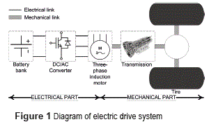
This section presents the model and description of the main components of the electric traction system proposed in this work. Figure 1 shows a diagram of electric traction system, which can be subdivided into electrical/electronic and mechanical part. The IM is part of both because this device performs the electrical to mechanical energy conversion. The following lines describe the operation and mathematical model of each of the electric traction system components shown in figure 1.
Battery bank
The battery bank is supposed with an ideal performance, i.e. it is considered as a source of constant DC voltage equal to 360 V. The battery bank consists of 30 batteries of 12 V each, connected in series.
DC/AC converter (inverter)
To operate the IM of EV by the battery bank, is needed a power electronic converter to transform the DC battery voltage to a three-phase AC voltage. This converter is known as a three-phase DC/AC converter, or simply three-phase inverter.
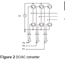
The converter used is a VSI, as shown in figure 2; it consists of six switching elements (IGBTs) and six freewheeling diodes. Ud represents the DC voltage of the battery bank. The three-phase AC voltage is obtained from the terminals a, b and c. For the DC/AC converter, the model presented in [19] is used._The output voltage space vector of the inverter  depends on the value of Ud and modulation signals Sa, Sb and Sc, as expressed in the equation (1).

Three-phase induction motor
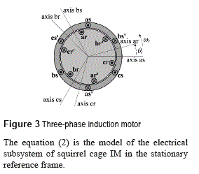
Figure 3 shows a diagram of three-phase squirrel cage IM, which is used for obtain its model [20], it shows the three phases of the stator as, bs y cs, and the equivalent three phases of the rotor ar, br y cr. θr is the angular position of the rotor and ωr is the angular velocity of the rotor.
The equation (2) is the model of the electrical subsystem of squirrel cage IM in the stationary reference frame.

where,  is the stator voltage space vector,
  and
and  are the space vector of stator and rotor currents, Rr and Rs are the resistances of stator and rotor,
 are the space vector of stator and rotor flux-linkage.
The flux-linkage space vectors are given by the equation (3).

with the inductances defined in the equation (4).

where, Ls is the total stator inductance,  is the stator self-inductance,
 is the mutual inductance between stator windings, Lr is the total rotor inductance,
  is the rotor self-inductance,
  is the mutual inductance between rotor windings, Lm is the magnetizing inductance, and
  is the peak value of the mutual inductance between stator and rotor windings.
The expression to calculate the torque developed by the IM is not unique, there are various. For example, the equation (5) for electromagnetic torque is used in DTC.

Where 
Other expression for the electromagnetic torque that is useful to estimate this one is presented in equation (6).

Transmission and tires
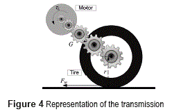
For the transmission-tires set, the torque provided to the load τL (EV in this case) by the electric motor is considered as input, and the output is the traction force Fte on the tires. If a simple transmission is considered, shown in the
figure 4, where r is the radius of the tire, ηg is the transmission efficiency, and G is the ratio of angular speed reduction.
The equations (7a) and (7b) model this type of transmission. Equation (7a) is used when the electrical machine delivers mechanical power, i.e. functions as motor (normal operation) and equation (7b) is used when the electrical machine receives mechanical power, i.e. functions as a generator (regenerative braking).

Likewise, in equation (8) the relation between the linear velocity v of the EV and the angular velocity ωr of the motor is shown.

Vehicle dynamics
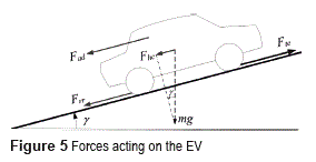
The forces acting on the EV moving on a slope with angle γ, are shown in figure 5.
The friction force Frr between the tires and the surface on which the vehicle moves is given by the equation (9).

where µrr is the friction coefficient, m is the total mass, g is the acceleration due to gravity, sign(·) is the sign function and v is velocity.
The force of friction with the wind is the equation (10).

Where ρ is the air density, A is the EV frontal area and Cd is the drag coefficient.
The equation (11) is the force Fhc required to move up the EV over a slope, is the component of weight along the slope.

Applying Newton's second law to the EV and using equations (9), (10) and (11), the equation (12) that relates the traction force Fte with speed v is obtained:

where a is the EV acceleration. Considering the equation (13) of torques of IM.
Considering the equation (13) of torques of IM.

where: τe is the electromagnetic torque, J is the total inertia (rotor and EV), B is the viscous friction coefficient of IM, ωr is the rotor mechanical angular velocity, and τL is the load torque.
In this case the motor load torque is the EV, therefore, it is possible to use equations (7a), (7b), (8), (12) and (13) to obtain the model of the mechanical part of the EV, equations (14a) and (14b).

So the EV model is given by the equations (1), (2) for the electric part, (5) for the torque developed by the motor and (14a), (14b) for the mechanic part.
Direct torque control
The DTC allows precise and fast control of flux and torque of the IM required by the EV dynamics. This control strategy is widely used in EV [12]. With this control technique fast dynamic response, low switching frequency, and reduced harmonics are achieved [13].
Flux-linkage and torque Estimator
For the DTC is necessary to estimate both the magnitude and angle of the stator flux-linkage space vector, as well as the electromagnetic torque. The estimation is based on the equation (2). The estimated stator flux-linkage space vector, equation (15), is obtained from the stator voltage equation [21].

 is the estimated stator flux-linkage space vector. To make this estimation the measurements of voltages and currents in the stator are used. This estimation also depends on the stator resistance.
Already known (by estimation) the value of the stator flux-linkage space vector, it is possible to estimate the electromagnetic torque by the equation (16).

Direct torque control switching table
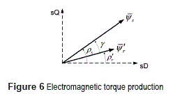
The DTC is based on the electromagnetic torque, equation (5), by expressing the torque in terms of the modulus  and the angles ρs and ρr, of the stator and rotor flux-linkage space vectors equation (17) is obtained [22].

figure 6 shows the space vectors involved in the production of the torque.
The rotor time constant of a standard squirrel- cage IM is large; thus the rotor flux-linkage changes only slowly compared to the stator flux- linkage [22], and can be assumed that the rotor flux-linkage are constant. Therefore, the torque control can be carried out using the stator flux- linkage space vector.
From (17) we can see that, holding constant  , the torque can be changed quickly by ρs-ρr . Thus, in the DTC drive instantaneous torque control can be achieved by quickly changing the position or the stator flux-linkage space vector relative to the rotor flux-linkage space vector, which moves slowly. Moreover, the flux-linkage space vector (both its modulus and its angle) can be changed by the stator voltage space vector. This can be seen from the stator voltage equation (18).

If the stator ohmic drop are neglected, (Rsis = 0), the equation (19) is obtained.

If a short Δt time is consider (which tends to zero), when the voltage vector is applied, the equation (20) is obtained.

Thus the stator flux-linkage space vector can be changed directly by the stator voltage space vector.
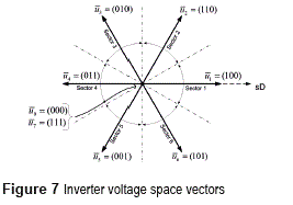
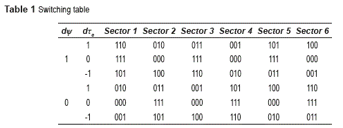
The inverter, shown in figure 2, can provide six active and two zero voltage space vectors, as shown in figure 7. Numbers in parentheses represent the inverter modulation signals Sa, Sb and Sc for each voltage space vector. Figure 7 also shows the six sectors of π/3 rad in which the plane is divided for the conventional DTC.
The inverter voltage space vector can be expressed as shown in equation (21).

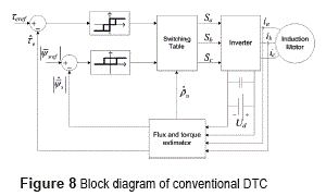
Figure 8 shows a block diagram of conventional DTC. The subscript ref indicates the reference values for the variables.
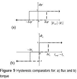
The DTC uses two comparators: a two levels hysteresis comparator for the flow error (Figure 9a) and a three levels hysteresis comparator for the torque error (Figure 9b).
Tolerance bands  set the allowable values for the flux and torque errors. If the output of flux comparator
  is: 1 a stator flux increase is required, and 0 a stator flux decrease is required. For the torque comparator, if its output
  is: 1 a torque increase is required, 0 no change in the torque is required, and -1 a torque decrease is required. According to the output of the flux and torque comparators, and the sector in which the stator flux-linkage space vector is located (see Figure 7), are the values that are sent to the inverter modulation signals Sa, Sb and Sc, see table 1.
Direct torque control with stator ohmic drop compensation
As mentioned in the previously, torque and flux control can be achieved by the stator flux-linkage space vector. If  is substituted in stator equation of the electrical subsystem of squirrel cage IM model, equation (22).

where the derivative of the modulus  and the derivative of the angle
  . of the stator flux-linkage space vector appear explicitly. Hence, the stator flux-linkage space vector can be directly manipulated by the stator voltage space vector. Equation (22) also shows the stator ohmic drop. Therefore, the compensation of this voltage drop is made if this equation is used to calculate the stator voltage space vector applied to the IM.
To perform flux control, the derivative of the modulus of the stator flux-linkage is equaled to the flux error multiplied by a constant, equation (23).

Where  is the gain of flux controller, and
  is the flux error.
From this, equation (24) can be obtained.

Therefore, the controller defined by equation (23) is equivalent to an integral controller that acts directly on the flux.
Moreover, the electromagnetic torque developed by the IM is proportional to the product of the modulus of the stator flux-linkage space vector and to the change of its position with respect to time (i.e. its time derivative), equation (25).

Therefore, the torque controller can be defined by the equation (26).

where k1 and k2 are the constants of torque controller, and et is the torque error.
Equation (26) is equivalent to a proportional-integral controller that acts directly on the torque developed by the IM.
Substituting flux and torque controllers, equations (23) and (26), in equation (22). The direct flux and torque control with stator ohmic drop compensation is obtained in equation (27).

The ohmic drop is an important term in the voltage equation, principally at low speeds. In EV the speed of IM varies in a wide range including low speeds.
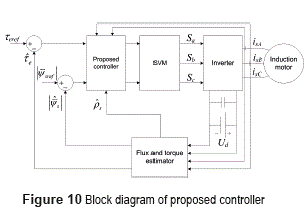
figure 10 shows the block diagram of the proposed controller, which is very similar to the block diagram of conventional DTC (figure 8). The main difference is the way in that the stator voltage space vector is calculated: in the case of conventional DTC is calculated using table 1, and in the proposed controller is calculated by equation (27). Another difference is the way in which inverter modulation signals (Sa, Sb and Sc) are generated: in the conventional DTC these come directly from table 1, and in the proposed controller SVM technique is used. Also in the proposed controller, unlike the conventional DTC, hysteresis comparators are not used.
Simulations
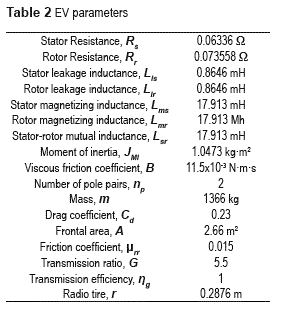
This section presents simulations to evaluate the performance of conventional DTC and the proposed controller. For both torque controllers were used: the same PI controller for speed regulation, the same desired speed profile, and the desired flux constant and equal to 0.8 Wb. The desired torque is the output of speed controller. The DC bus voltage is 360 V. EV parameters are given in table 2.
DTC with switching table
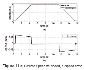
The values of the hysteresis band used are Δψ= 0.01 Wb and Δte = 2.5 Nm. With these values a maximum switching frequency of approximately 30 kHz was obtained. The desired speed and the speed developed by the EV are shown in figure 11a and in figure 11b is presented the speed error which fluctuates between ±0.0268 m/s.
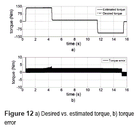
The desired torque (i.e. the output of speed controller) and the estimated torque are shown in figure 12a. The torque error, presented in figure 12b, do not remain at all times within the hysteresis band Δte = 2.5 Nm.
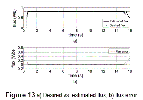
The estimated flux has a good track on to the desired flux (figure 13) during the interval of time 0.5s < t < 15.5s. From 0 to 0.5 s and at the last 0.5 s simulation, flux tracking is not good because during this time the torque error is practically zero and, according to table 1, the inverter voltage is zero.
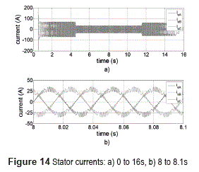
The magnitude ofthe currents in the statorwindings is closely related with the electromagnetic torque developed; hence its value varies along the simulation time as shown in figure 14a. A close to the currents during the interval of time from 8 to 8.1s is shown in figure 14b.
DTC with stator ohmic drop compensation
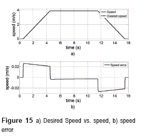
Figure 15 presents the desired speed and the speed developed by the EV, as well as the speed error. The desired speed is the same as for conventional DTC likewise the speed developed by the EV and speed error are very similar to those obtained inthe simulation of conventional DTC (Figure 11), this is because the speed controller is the same for both simulations.
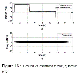
The desired torque and estimated torque are shown in figure 16a. The torque error presented in figure 16b is lower than that obtained for conventional DTC. For the proposed controller torque error does not exceed ±1.3 Nm. Although both controllers have a suitable tracking of torque, the torque ripple is smaller in the proposed controller.
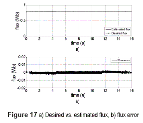
As shown in figure 17, flux control also has better performance in the proposed controller that in the conventional DTC. The flux error, after passing the transitory is very small, it oscillates between ±3x10⁻³ Wb.
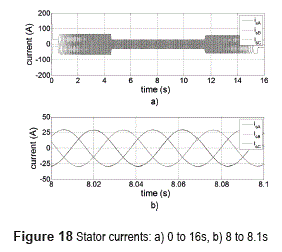
Stator currents are shown infigure 18, its magnitude is very similar to those obtained with conventional DTC. However, as shown in figure 18b, its distortion is much lower in the proposed controller.
Conclusion
The conventional DTC is a good option for torque control of IM that impulse EV. It is simple to implement. It has fast response and good dynamic performance. However, it has some drawbacks: high torque ripple, and variable inverter switching frequency. The values of the hysteresis bands for flux and torque controllers play a key role in the performance of the conventional DTC. If very large values are using, shall be poor performance, while resulting in low switching frequency. Instead, if too small values are used significantly improves performance, but also increases the switching frequency and the limit imposed by semiconductor devices could be exceeded.
Based on the principle of DTC, it follows that the torque and flux control can be carried out through the stator flux-linkage space vector. Moreover, the stator flux-linkage space vector can be modified directly by the stator voltage space vector. A new improvement direct flux and torque control with stator ohmic drop compensation were obtained. The ohmic drop is an important term in the voltage equation, principally at low speeds.
Based on the simulation results for: torque and flux errors, and distortion in the stator currents, it is shown that the performance of the proposed controller is higher that the performance of conventional DTC.
References
1. C. Chan. ''Present status and future trends of electric vehicles''. Advances in Power System Control, Operation and Management. Vol. 1. 1993. pp 456-469. [ Links ]
2. D. Naunin. Electric vehicles. Proceedings of the IEEE International Symposium on Industrial Electronics. Warsaw, Poland. Vol. 1. 1996. pp. 11-24. [ Links ]
3. J. Larminie, J. Lowry. Electric Vehicle Technology Explained. 1st ed. Ed. John Wiley & Sons Ltd. Great Britain, RU. 2003. pp. 7-21. [ Links ]
4. S. Sallem, M. Chaabene, Be. Kamoun. A robust nonlinear of an Electric Vehicle in traction. Systems. Proceedings of the Signals and Devices. Djerba, Túnez. 2009. pp. 1-6. [ Links ]
5. A. Foley, B. Gallachoir, P. Leahy, E. McKeogh. Electric Vehicles and energy storage - a case study on Ireland. Proceedings of the Vehicle Power and Propulsion Conference. Dearborn, USA. 2009. pp. 524-530. [ Links ]
6. R. Chicurel, G. Carmona, E. Chicurel, F. Gutierrez. Contribution of the National University of Mexico to Electric Vehicle Technology. Proceedings of the Electronics, Robotics and Automotive Mechanics Conference. Cuernavaca, México. 2006. pp. 123-130 [ Links ]
7. F. Perez, G. Nuñez, R. Alvarez, M. Gallegos. Step by step design procedure of an Independent-Wheeled Small EV applying EVLS. Proceedings of the IEEE Annual Conference on Industrial Electronics. Paris, Francia. 2006. pp. 1176-1181. [ Links ]
8. I. Alcalá, A. Claudio, G. Guerrero. Analysis of propulsion systems in electric vehicles. Proceedings of the International Conference on Electrical and Electronics Engineering. 2005. pp. 309-313. [ Links ]
9. O. Diaz. Environmental friendly electric transport for large cities. The case of Mexico City. Proceedings of the International Symposium on Industrial Electronics. Cholula, México. Vol. 1. 2000. pp. 1-4. [ Links ]
10. L. Takahashi, T. Noguchi. ''A new quick-response and high efficiency control strategy of an induction motor''. IEEE Trans. Ind. Appl. Vol. IA-22. 1986. pp. 820-827. [ Links ]
11. M. Depenhrock. ''Direkte Selbstregelung (DSR) fiir hochdynamische Drehfeld-antriebe mit Stromrichterschaltung''. ETZA 7. Germany. 1985. pp. 211-18. [ Links ]
12. B. Singh, P. Jain, A. Mittal, J. Gupta. Direct torque control: a practical approach to Electric vehicle. Proceedings of the IEEE Power India Conference. New Delhi, India. 2006. pp. 1-6. [ Links ]
13. A. Bazzi, A. Friedl, S. Choi, P. Krein. Comparison of induction motor drives for electric vehicle applications: Dynamic performance and parameter sensitivity analyses. Proceedings of the IEEE International Electric Machines and Drives Conference. Florida, USA. 2009. pp. 639-646. [ Links ]
14. J. Faiz, M. Sharifian, A. Keyhani, A. Proca. ''Sensorless Direct Torque Control of Induction Motors Used in Electric Vehicle''. IEEE Transactions on Energy Conversion. Vol. 18. 2003. pp. 1-10. [ Links ]
15. N. Idris, C. Toh, M. Elbuluk. ''A New Torque and Flux Controllers for Direct Torque Control of Induction Motors''. IEEE Transactions on Industry Applications. Vol. 42. 2006. pp. 1358-1366. [ Links ]
16. A. Haddoun, M. Benbouzid, D. Diallo, R. Abdessemed, J. Ghouili, K. Srairi. Comparative Analysis of Control Techniques for Efficiency Improvement in Electric Vehicles. Proceedings of the IEEE Vehicle Power Propulsion Conf. Arlington, USA. 2007. pp. 629-634. [ Links ]
17. E. Hassankhan, D. Khaburi. ''DTC-SVM Scheme for Induction Motors Fed with a Three-level Inverter''. World Academy of Science, Engineering and Technology. Vol. 2. 2008. pp. 168-172. [ Links ]
18. M. Vasudevan, R. Arumugam. Simulation of Viable Torque Control Schemes of Induction Motor for Electric Vehicles. Proceedings of the Asian Control Conference. Greensboro, USA. 2004. pp. 1377-1383. [ Links ]
19. A. Trzynadlowski. Control of Induction Motors. 1st ed. Ed. Academic Press. USA. 2001. pp 64-81. [ Links ]
20. C. Ong. Dynamic Simulation of Electrical Machinery: Using Matlab/Simulink. 1st ed. Ed. Prentice Hall. New Jersey, USA. 1998. pp. 167-243. [ Links ]
21. J. Faiz, M. Sharifian. ''Different techniques for real time estimation of an induction motor rotor resistance in sensorless direct torque control for electric vehicle''. IEEE Trans. on Energy Conversion. Vol. 16. 2001. pp. 104-109. [ Links ]
22. P. Vas. Sensorless Vector and Direct Torque Control. 1st ed. Ed. Oxford University Press. Oxford, UK. 1998. pp. 505-559. [ Links ]


