Services on Demand
Journal
Article
Indicators
-
 Cited by SciELO
 -
 Access statistics
Related links
-
 Cited by Google
 -
 Similars in
SciELO
 -
 Similars in Google
Share
Revista Facultad de Ingeniería Universidad de Antioquia
Print version ISSN 0120-6230
Rev.fac.ing.univ. Antioquia no.74 Medellín Jan./Mar. 2015
ARTÍCULO ORIGINAL
New Relation to Improve the Speed and Torque Characteristics of Induction Motors
Nueva relación para mejorar la característica de velocidad y par de motores de inducción
Luis Antonio Mier-Quiroga1*, Jorge Samuel Benítez-Read1,2, Régulo López-Callejas1,2, José Armando Segovia-de-los-Ríos1,2
1 División de Estudios de Posgrado e Investigación, Instituto Tecnológico de Toluca. Av. Tecnológico s/n, Ex-rancho La Virgen, Metepec. C.P. 52140. Estado de México, México.
2 Instituto Nacional de Investigaciones Nucleares. Carretera México Toluca, La Marquesa, Ocoyoacac. C.P. 52750 Estado de México, México.
* Corresponding author: Luis Antonio Mier Quiroga, e-mail: luanmiq@yahoo.com.mx
(Received November 15, 2013; Accepted October 27, 2014)
Abstract
Squirrel cage induction motors are employed in a wide variety of applications. Operating at constant speed is required in some applications, whereas variation of this parameter is required in others, as in the provision of mechanical energy to electrical vehicles. The performance of an electric vehicle is specified by the characteristics of the electric motor. The adequate relation between the voltage magnitude and the frequency of its power source makes the motor satisfy the electric vehicle requirements. The voltage magnitude is a function of the frequency of operation. If the V - f relation is adequate, the motor speed response could be improved. A new V - f relation that improves the speed response of the single squirrel cage induction motor is presented and is defined by a frequency factor. For motor speeds below the nominal value, the torque capacity of the motor is preserved with the proposed relationship.
Keywords: V - f relation, induction motor, speed response
Resumen
Los motores de inducción jaula de ardilla son empleados en gran variedad de aplicaciones. Ciertas aplicaciones requieren su operación a velocidad constante y en otras se requiere su operación a diferentes velocidades, como es el caso de proveer energía mecánica a vehículos eléctricos. El desempeño de un vehículo eléctrico depende de las características del motor eléctrico. La relación adecuada entre la magnitud del voltaje y la frecuencia de la fuente de alimentación permite que el motor cumpla con los requisitos del vehículo eléctrico. La magnitud del voltaje está en función de la frecuencia de operación. Si es adecuada la relación V - f , se puede mejorar la respuesta en velocidad del motor. Se presenta una nueva relación V - f , definida por un factor de frecuencia, que mejora la respuesta en velocidad del motor de inducción de rotor sencillo de jaula de ardilla. Para velocidades menores a la nominal, se mantiene la capacidad de par del motor con la relación propuesta.
Palabras clave: relación V - f, motor de inducción, respuesta en velocidad
Introduction
The squirrel cage induction motor (IM) is one of the electrical machines used to provide traction to electric vehicles (EV), hybrid electric vehicles (HEV) and fuel cell electric vehicles (FCEV) [1-3]. The main requirements for electric motors drives in EV, HEV and FCEV are wide speed range operation, high torque and fast speed response in low speeds and constant power in high speeds [1, 2, 4]. In order to modify the IM speed, the frequency (ƒ) of the power source is established according to the desired speed [5]. Commonly, the voltage magnitude (V) of the IM power source maintains a constant relation with ƒ[6]. For motor speeds below the nominal value, the same torque capacity of the IM cannot be preserved with a constant  relation [7, 8]. Some research groups have proposed techniques to keep a constant motor torque at low velocities [9, 10].
In this work, a new  relation that improves the speed response of the IM is presented. The proposed
  relationship is defined by a frequency factor that expresses the relation of the operating frequency of the IM to its nominal value. The variations in the reactances of the IM are considered and defined by the frequency factor. Although the IM is operated in open loop, the goal, by using the proposed
  relationship, is to maintain a constant torque at each operating frequency. The experiments are carried out for different motor velocities with and without mechanical load applied to the motor shaft. The results using the proposed
  relation are compared to those obtained with the commonly used
  method, In a further work, this new
  relationship will be used by a control system to fulfill the EV demands.
Performance requirements of electric motors in EV, HEV and FCEV
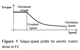
The performance of EV, HEC or FCEV is specified by the torque-speed characteristic of the electric motor [2, 11]. The profile required is shown in figure 1 [2, 4, 12]. It can be seen that the electric motor develops a constant torque from the motor start up until it reaches its nominal speed. If the motor speed continues increasing, after the nominal value, the torque decreases.
The main desired characteristics of electric motors driving EV are [2, 4, 13]:
– High instantaneous power and high power density.
– High torque in low speeds from start up to nominal speed.
– Wide speed range with constant torque region and constant power region.
– Fast torque and speed response.
– High efficiency in wide speed ranges.
– Robustness in several operation circumstances.
– Reasonable cost.
– Low maintenance.
– Reduced volume and weight.
The permanent magnet motor (PMM) has high torque and power density, develops constant torque at low speeds and is small in volume and weight. However, at high speeds, this type of motor presents appreciable losses with a consequent low efficiency. For the same torque and power ratings, PMM is more expensive than both IM and direct current motors (DCM) [1, 2, 12]. These motors have low efficiency and need more maintenance than IM, PMM and switched reluctance motors (SRM). Additionally, the DCM has low power density and torque [2, 14]. IM is more efficient than DCM, but less efficient than both PMM and SRM. In applications for electric propulsion of EV, IM is the preferred type due to its reliability, ruggedness, low maintenance and ability to operate in wide ranges of speed [15]. The cost of the IM is comparable to the SRM and less expensive than the PMM and DCM [1, 2, 12]. The SRM can operate at extremely high speeds and, at low speeds, their torque is large. Their main disadvantages are acoustic noise generation, torque ripple and excessive electromagnetic interference (EMI) [1, 2, 12].
The squirrel cage Induction Motor
The IM is composed of a group of thin laminated steel sheets arranged into a cylinder with slots. Coils are inserted into the slots. Each coil group constitutes an electromagnet. The number of poles depends on the internal connection of the stator coils. The squirrel cage rotor is a cylinder made of aluminum bars. The bars are connected mechanically and electrically by ending rings. Considering the stator connected to the source, the generated magnetic field of the stator rotates at Ssync (expressed in rpm); therefore, the rotor is inside of an electromagnetic field. An electromotive force (EMF) is produced in the rotor. The rotor current, produced by the rotor induced EMF, generates an electromagnetic field that has opposed polarity with respect to the stator electromagnetic field. Consequently, the interaction between both fields produces an electromagnetic torque in the rotor which makes it rotate in the direction of the stator electromagnetic field.
There is a difference between Ssync and the rotor speed (Sr). The speed difference is named slip speed and the sliding, is expressed, according to equation (1), as relative error with respect to Ssync[5]:

Ssync is given by equation (2) [5]:

where ƒ is the stator voltage frequency and P (equation (3), is the number of stator poles expressed by the number of slots in a pole per phase (n), as:

From equation (1), we can derivate equation (4) in order to express the rotor speed as:

This equation indicates that rotor speed can be adjusted with the frequency of the IM source.
If the rotor is blocked (S=1) and the stator connected to the power source, the frequency of the sinusoidal voltages and currents induced in the rotor (ƒr), is equal to ƒ. In theory, if Sr=Ssync, there would have not been induced any EMF in the rotor and the rotor would not rotate. The frequency of the induced EMF in the rotor changes in inverse proportion to Sr. The frequency variation starts in a maximum point (power source frequency) and is decreasing as Srincreases (with s≈0). The frequency of the rotor induced EMF is expressed by equation (5):

The rotor bars have low electrical resistance, as well as an inductance (Lr) and inductive reactance (Xr) properties. The inductive reactance of the rotor  is computed with the rotor blocked [3, 16]. Considering that ƒrincreases proportionally to the value of s, the rotor inductive reactance can be expressed by equation (6) [5]:

The EMF induced in the rotor, when its blocked, is defined by equation (7) [5]:

where Κ is a constant that represents rotor bars features and φ is the stator magnetic field. The induced EMF in the rotor (Er), expressed by equation (8), for any value of ƒr can be expressed in function of E1r and s:

The frequency of the induced EMF in the rotor (ƒr) starts at the value of the stator voltage frequency (ƒ) with the rotor blocked (s=1), and decreases down to zero when the shaft attains the synchronous speed (s ≈ 0).
The torque with the rotor blocked can be determined by the current in the rotor according to equation (9) [5]:

where Kt is a constant that depends on the stator coil characteristics, and  is the current component of the rotor in phase with Φ.
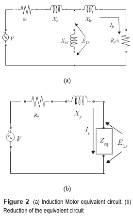
The equivalent circuit of the single cage IM is shown in figure 2. The circuit is a model in steady state and allows obtaining the equations that define the IM behavior [17, 18]. The mutual reactance jXm represents the difference between stator and rotor inductances. The impedance of the stator is represented by Rs and Xs. The effective rotor resistance is represented by Rr/s. The s term takes into account the apparent increment of Rr when the rotor is moving. E1r represents the reactance when s=1 [5].
From figure 2(a), it can be seen that the rotor current magnitude Ir, with the rotor blocked, is expressed according to equation (10) [5]:

By substituting equation (10) into equation (9) and considering that  equation (11) expresses the initial value of the rotor torque [5]:

For any value of s, considering equations (6) and (8), equation (12) indicates that rotor current is:

The term, at any value of s, is 

Hence, equation (13) expresses that, for a given sliding the torque of the IM is [5]:

The equation (14) can be derived considering equations (7) and (8):

Therefore, the stator magnetic field, expressed by equation (15), is:

By substituting equation (15) into equation (13), the torque magnitude is expressed by quation (16) as:

As stated before, a region of constant torque is demanded for speeds below the nominal. Commonly, the voltage magnitude of the motor power source is modified in direct proportion to the frequency. When the frequency is larger than the nominal, the voltage magnitude is the nominal value. In order to determine the value of E1r the losses of the stator are neglected, then E1r=V [10, 15].
To determine the real value of E1r , and the real value of the torque, Rs and Ls should be considered. The equivalent circuit of the IM can be reduced to the circuit shown in figure 2(b). The magnitude of the equivalent impedance is expressed by equation (17):

when the rotor is blocked, equation (17) reduces to equation (18):

According to the circuit of figure 2(b), the magnitude of V can be expressed by equation (19):

and the stator current, Is , is expressed according to equation (20):

Hence, by substituting equation (20) into equation (19), Er is given by equation (21) as:

The equation (22) expresses Er when the rotor is blocked:

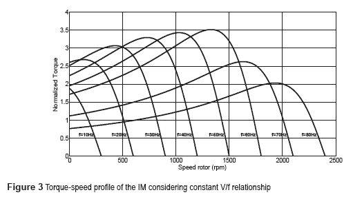
Figure 3 shows the torque-speed profile described by equation (16). The torque is normalized with respect to the nominal torque value and E1r is obtained with equation (22). Each curve represents the real torque response for a given frequency with the voltage computed according to the V/ƒ relation commonly considered. The value of the relation is V/ƒ=5.3 Volts/hertz. The rotor starts blocked and is subsequently released, allowing the rotor speed to attain the synchronous speed. The IM ratings are shown in table 1.
The torque-speed profile in figure 3 shows that the motor torque capacity decreases in direct proportion with velocity decrements. To compensate this torque response, the V/ƒ relation is increased at low speeds [10, 15].
The proposed  relationship
This section describes the method to compute the proposed  relationship, which allows the IM to approach the torque-speed profile shown in figure 1 and to improve the speed response. Taking into account equation (16), the torque at nominal frequency (ƒn) can be expressed by equation (23):

The torque for a given frequency, lower than the nominal and that we call operation frequency ( ƒm ), is expressed by equation (24) as:

Considering the torque invariant for any power source frequency, that is, Tn=Tm , if the relation between nominal frequency and the given frequency is expressed, by equation (25) through an unknown variable X= ƒn/ƒm, called frequency factor, then:

The frequency factor must be calculed each operation speed of the IM, in order to include the frequency influcence in the elements of the equivalent circuit shown in figure 2. Hence, this factor appears in the calculation of the magnitud of V.
Replacing equation (25) in Tn=Tm , the equation (26) is obtained:

Then, the induced EMF in the rotor ( E1rm ) for a given frequency is expressed by equation (27):

From equation (22), the power source voltage magnitude required to produce E1rm at the nominal frequency is obtained with equation (28):

Hence, the power source voltage magnitude required for any given frequency is expressed by equation (29) as:

Where equation (30) must be considered:

Equations (27) and (30) are defined by the IM parameters. There exist several methods to determine the IM parameters [5, 15, 16].
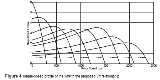
Figure 4 shows the torque-speed profile described by equation (16). The torque is normalized with respect to the nominal torque value. Each curve represents the torque response for a given frequency with the voltage computed by equation (29), where the variables X, E1rm and the losses are computed according to the given frequency. Considering that rotor starts blocked (s=1), and is subsequently released, allowing the rotor speed to attain the synchronous speed (s=0). It can be seen in figure 4 that the torque developed by the motor, specially, at low frequencies is higher than the torque obtained by the motor with the constant V/ƒ relationship as is shown in figure 3.
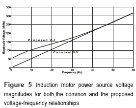
The power source voltage magnitudes required for the IM using the common V/ƒ and the proposed  relationships are shown in figure 5. For the ''constant '' V/ƒ plot, the magnitude voltage is computed multiplying the frequency value for the V/ƒ relationship. In the case of the ''Proposed
  '' plot, the magnitude voltage is computed acording to equation (29), where stator and rotor losses are considered according to operation frequency and factor frequency.
Results
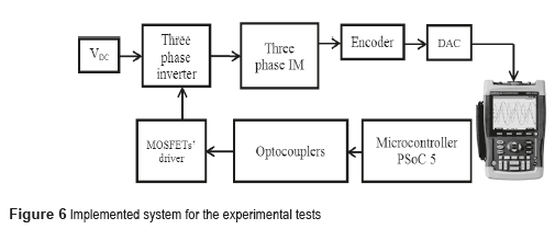
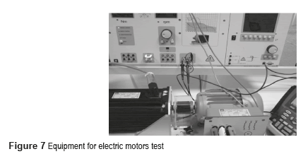
The system shown in figure 6 was implemented to compare the IM behavior obtained with the constant V/ƒ versus the proposed  relations. The IM used has the ratings listed in table 1. The experimental tests were made implementing a sudden acceleration until the rotor speed attains the set value, with and without a 5 Nm load. The load was applied with the Lucas-Nülle didactic equipment for electric motor tests showed in figure 7. A motor-brake coupled to the IM shaft is part of the equipment. The control console allows set the required load (expressed in Newton-meters).
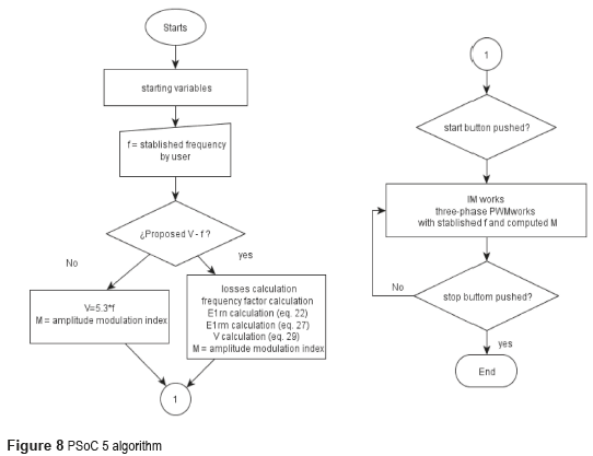
The programmable system on chip microcontroller (PSoC 5), performs the three phase pulse width modulation (PWM). The PWM provides the adequate pulses to switch the MOFETs in the three phase inverter. The inverter supplies the voltage and frequency to the IM in order to produce a three phase balanced system. The frequency of the voltage source is established in the PSoC 5. This microcontroller runs the algorithm that computes the amplitude modulation index required by both, the common V/ƒ and the proposed  relationship, according to the flow chart showed in the figure 8.
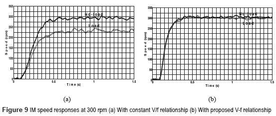
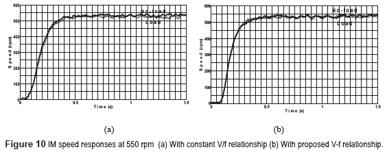
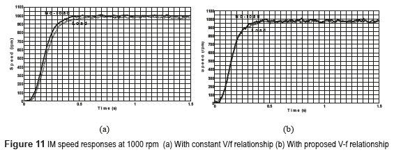
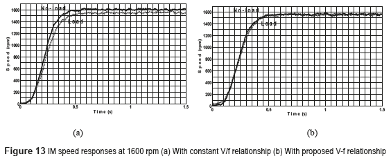
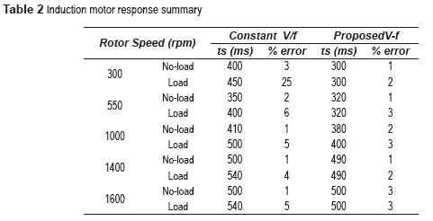
In the rotor of the IM, an encoder and DAC were mounted to measure the speed response with the help of a fluke scopemeter. The scopemeter allows, using an isolated USB cable, to capture the voltage generated by DAC; this voltage matches with the speed response of motor. The IM speed responses for 300 rpm are presented in figure 9. In figures 9(a) and 9(b), the responses with V/ƒ=5.3 and the proposed  relation are shown, respectively. Similarly, the results at 550 rpm, 1000 rpm, 1400 rpm and 1600 rpm are shown in figures 10, 11, 12 and 13, respectively.
Table 2 shows the summary of the IM responses.
The results obtained for the open loop system (figure 6) using the relation  proposed show a settling time reduction in all cases and a significant error decrement with load, especially at low speeds. This response matches the response plotted in Figure 4, where the torque is bigger at low frequencies. The obtained responses show a similar speed ripple response of the IM when compared with experimental results reported for an IM speed fuzzy control [19], and less ripple than the results presented in [20]. Simulation results presented with control techniques commonly used for the IM show similar speed ripple and settling time responses compared with those presented herein [21-23].
Conclusions
A model of a single squirrel cage induction motor that considers the power losses as a function of the inverter operating frequency, was developed. The stator losses should not be neglected in applications of variable speed as they are significant, particularly at low speeds. Hence, the voltage magnitude obtained with the constant V/ƒ relationship was lower than those computed with the proposed  relationship. The aim of the analysis presented was to derive a new expression for the power supply voltage as function of the frequency of operation to improve the motor speed dynamic response and to reduce the torque variation at different motor shaft velocities below the nominal value. A series of experiments was designed to examine the speed response of the motor. The results using the proposed
  relation were compared to those obtained with the commonly used V/ƒ method. Using the magnitude of the power supply voltage derived here, the settling time was reduced in all cases. Likewise, at low velocities, when the constant V/ƒ relation was used, the steady state speed was reduced when the load was applied. In contrast, it could be appreciated that, when the new
  relation was used, the steady state speed attained with the load applied, was very close to the speed of the motor without load. In the near future, this
  relation will be incorporated into a control scheme, which is expected to comply with the speed and torque characteristics demanded on electrical motors used for mechanical traction in EV.
References
1. C. Chan. ''The State of the Art of Electric, Hybrid and Fuel Cell Vehicles''. Proceedings of the IEEE. Vol. 95. 2007. pp. 704-718. [ Links ]
2. X. Xue, K. Cheng, N. Cheung. Selection of Electric Motors Drives for Electric Vehicles. Proceedings of the Australasian Universities Power Engineering Conference (AUPEC '08). Sydney, Australia. 2008. pp. 1-6. [ Links ]
3. E. Beltrán. Control Directo de Par de un Motor de Inducción Trifásico con Aplicación a Vehículos Eléctricos. Master's Thesis, CENIDET. Cuernavaca, México. 2011. pp. 43-90. [ Links ]
4. M. Zeraoulia, M. Hachemi, D. Diallo. ''Electric Motor Drive Selection Issues for HEV Propulsion Systems: A Comparative Study''. IEEE Transactions on Vehicular Technology. Vol. 55. 2006. pp. 1756-1764. [ Links ]
5. I. Kosow. Electric Machinery and Transformers. 2nd ed. Ed. Prentice Hall. New Delhi, India, 1992. pp. 308-345. [ Links ]
6. M. Brejl, M. Princ, P. Uhlir. AC Induction Motor Volts per Hertz Control with Speed Closed Loop, Driven by eTPU on MPC5500. Application Note. Freescale Semiconductor Inc. Colorado, USA. 2006. pp. 4-10. [ Links ]
7. R. Araujo, H. Teixeira, J. Barbosa, V. Leite. A Low Cost Induction Motor Controller for Electric Vehicles in Local Areas. Proceedings of the International Symposium on Industrial Electronics, (ISIE). Dubrovnik, Croatia. 2005. pp. 1499-1504. [ Links ]
8. S. Bowling. An Introduction to AC Induction Motor Control Using the dsPIC30F MCU. Application Note. Microchip Technology Inc. Georgia, USA. 2005. pp. 6-10. [ Links ]
9. M. Tsuji, S. Chen, S. Hamasaki. A Novel V/f Control of Induction Motors for Wide and Precise Speed Operation. Proceedings of the International Symposium on Power Electronics, Electrical Drives, Automation and Motion (SPEEDAM). Ischia, Italy. 2008. pp. 1130-1135. [ Links ]
10. C. Ogbuka, M. Agu. A Modified Approach to Induction Motor Stator Voltage and Frequency Control. Proceedings of the World Congress on Engineering, Vol. II. London, UK. 2011. pp. 44-51. [ Links ]
11. J. Guzinski, H. Abu. ''Sensorless Induction Motor Drive for Electric Vehicle Application''. International Journal of Engineering, Science and Technology. Vol. 2. 2010. pp. 20-34. [ Links ]
12. M. Ehsani, Y. Gao, J. Miller. ''Hybrid Electric Vehicles: Architecture and Motor Drives''. Proceedings of the IEEE. Vol. 95. 2007. pp. 719-728. [ Links ]
13. A. Arif, A. Betka, A. Guettaf. ''Improvement the DTC System for Electric Vehicles Induction Motors''. Serbian Journal of Electrical Engineering. Vol. 7. 2010. pp. 149-165. [ Links ]
14. A. Fekih. A New Sliding-Mode Based Control Design for Induction Motors Propelling Electric Vehicle Drives. Proceedings of the 10th International Conference on Control, Automation, Robotics and Vision (ICARCV). Hanoi, Vietnam. 2008. pp. 1066-1071. [ Links ]
15. A. Hughes. Electric Motor and Drives, Fundamentals, Types and Applications. 3rd ed. Ed. Newnes-Elsevier. Oxford, UK. 2006. pp. 167-263. [ Links ]
16. J. Cathey. Electric Machines: Analysis and Design Applying MATLAB. 1sted. Ed. McGraw Hill. Ohio, USA. 2001. pp. 336-350. [ Links ]
17. M. Haque. ''Determination of NEMA design induction motor parameters from manufacturer data''. IEEE Transactions on Energy Conversion. Vol. 23. 2008. pp. 997-1004. [ Links ]
18. K. Lee, S. Frank, P. Sen, L. Gentile, M. Alahmad, C. Waters. Estimation of Induction Motor Equivalent Circuit Parameters from Nameplate Data. Proceedings of the IEE North American Power Symposium. Champaign, USA. 2012. pp. 1-6. [ Links ]
19. I. Birou, V. Maier, S. Pavel, C. Rusu. Indirect Vector Control of an Induction Motor with Fuzzy Logic based Speed Controller. Proceedings of the 3rd International Symposium on Electrical Engineering and Energy Converters. Suceava, Rumania. 2009. pp. 149-154. [ Links ]
20. V. Chitra, R. Prabhakar. Induction Motor Speed Control using Fuzzy Logic Controller. World Academy of Science, Engineering and Technology. Vol. 23. 2006. pp. 17-22. [ Links ]
21. S. Belkacem, F. Naceri, R. Abdessemed. ''Reduction of the Torque Ripple in DTC for Induction Motor Using Input-Output Feedback Linearization''. Serbian Journal of Electrical Engineering. Vol. 8. 2001. pp. 97-110. [ Links ]
22. A. Arif, A. Betka, A. Guettaf. ''Improvement the DTC System for Electric Vehicles Inductions Motors''. Serbian Journal of Electrical Engineering. Vol. 7. 2010. pp. 149-165. [ Links ]
23. A. Nazeer, A. Sadik, K. Ravi, M. Prasanti. ''Novel DTC-SVM for an Adjustable Speed Sensorless Induction Motor Drive''. International Journal of Science Engineering and Advance Technology. Vol. 2. 2014. pp. 31-36. [ Links ]


