Services on Demand
Journal
Article
Indicators
-
 Cited by SciELO
 -
 Access statistics
Related links
-
 Cited by Google
 -
 Similars in
SciELO
 -
 Similars in Google
Share
Revista Facultad de Ingeniería Universidad de Antioquia
Print version ISSN 0120-6230
Rev.fac.ing.univ. Antioquia no.74 Medellín Jan./Mar. 2015
ARTÍCULO ORIGINAL
Band-Pass Filters Using OSRR Cells
Filtro pasa banda usando celdas OSRR
Iván Díaz-Pardo1, Carlos Arturo Suárez-Fajardo1*, Gustavo Puerto-Leguizamón1, Tatiana Zona-Ortiz2
1 Laboratorio de Ingeniería de Microondas Electromagnetismo y Radiación (LIMER), Universidad Distrital Francisco José de Caldas. Cr 7 N.° 40B-53. C.P. 111031. Bogotá, Colombia.
2 Grupo de investigación ESINUSA, Universidad Sergio Arboleda. Calle 74 N.° 14-14. C.P. 110231. Bogotá, Colombia.
* Corresponding author: Carlos Arturo Suárez Fajardo, e-mail: csuarezf@udistrital.edu.co
(Received September 19, 2013; Accepted September 30, 2014)
Abstract
This paper presents the design process (including optimization and characterization) of a band-pass filter through the use of OSRR-structured meta-material cells over micro-strip substrates. The proposed design, which stems from the OSRR cell model, includes a partial ground plane etched at the bottom plane instead of, and square windows etched at the bottom plane and achieve optimization through a parametric analysis carried out over the transmission-line segments that connect the cells to the main transmission line as well as over inter-cell lines. The results yielded a resonance central frequency and a corresponding bandwidth of 2.7 GHz and 700MHz, respectively. By controlling the length of the connecting lines from the cells to the main transmission line, it is possible to tune the central frequency to a lower frequency than that of an OSRR cell. With respect to the ground plane windows version, the partial ground plane version has the capacity to add transmission zero (4.6GHz) above a/the transmission pole, which improves the rejection depth (8dB) without increasing the filter size.
Keywords: Meta-materials, plane filters, Split Ring Resonators (SRR)
Resumen
Este articulo presenta el proceso de diseño (incluyendo optimización y caracterización) de un filtro pasa banda mediante la utilización de celdas metamaterial en estructura OSRR (Open Split Ring Resonator) sobre sustratos microstrip. El diseño propuesto parte del modelo de celdas OSRR, incluye un plano de masa parcial depositado en el plano posterior en vez de ventanas cuadradas depositadas en el plano posterior y se optimiza mediante análisis paramétricos llevados a cabo sobre los tramos de línea de transmisión que unen las celdas a la línea de transmisión principal, al igual que sobre las líneas que unen las celdas. La frecuencia central de resonancia y ancho de banda obtenidos fueron de 2.7 GHz y 700 MHz respectivamente. Controlando la longitud de las líneas de conexión de las celdas a la línea de transmisión principal se logra sintonizar el filtro a una frecuencia más baja que la de una celda OSRR. La versión con plano de masa parcial tiene la capacidad de adicionar un cero en transmisión (4.6GHz), arriba del polo de transmisión, lo cual mejora la profundidad de la banda de rechazo (8dB) respecto a la versión que incluye ventanas en el plano de masa, sin incrementar el tamaño del filtro.
Palabras clave: Metamateriales, filtros planos, resonador de anillos abiertos (SRR)
Introduction
Modern applications in microwave and millimeter bands require the design of small-size, high-performance devices and circuits. Moreover, these applications require a substantial reduction of spurious signals as well as of undesired harmonic components.
Recent studies have offered a solution to such problems by controlling the electromagnetic properties of some materials. These solutions implement periodic structures (called meta-materials) that are comparable in size to the dimensions of the design wavelength. One of the most representative examples is that of the so called left-handed media, which distinct characteristic is to exhibit negative values of effective dielectric permittivity and also of magnetic permeability; which produces reversal waves [1, 2]. Although the implementation of meta-materials was achieved in the 21st century, since the 20th century there were already proposals of structures that could modify the natural electromagnetic behavior [3]. The main purpose of meta-materials technology is to miniaturize and improve the capabilities of microwave devices such as antennas, filters and power splitters, among other devices [4, 5].
In [6], a complete approach for the development of planar metamaterial structures is developed. For this purpose, split-ring resonators (SRRs) and complementary split-ring resonators (CSRRs) coupled to planar transmission lines are investigated. The electromagnetic behavior of these elements, as well as their coupling to the host transmission line are studied, and analytical equivalent-circuit models are proposed for the isolated and coupled SRRs/CSRRs. From these models, the stopband/passband characteristics of the analyzed SRR/CSRR loaded transmission lines are derived. It is shown that, in the long wavelength limit, these stopbands/passbands can be interpreted as due to the presence of negative/positive values for the effective and of the line. The proposed analysis is of interest in the design of compact microwave devices based on the metamaterial concept.
In [7], a sub wavelength resonator called an open complementary split ring resonator (OCSRR) is used to design a bandstop filter. Two open stubs of length λ/4 and a single OCSRR are employed for the design of bandstop filter. The open stubs are folded in opposite direction to achieve a compact structure. The proposed bandstop filter has a rejection band of 2.25 GHz. When compared to a conventional bandstop filter, the rejection bandwidth of the proposal is increased by 59.11% and size is reduced by 15%.
In [8], a new electric split-ring resonator (ESRR) specialized for the double-sided parallel-strip line (DSPSL) is proposed. Adding a DSPSL swap to a split-ring resonator (SRR), its magnetic response becomes electrical, which is explained by even and oddmode analysis and resonant current distribution. Loading in a line with a series gap, it behaves similarly to the previously well-studied complementary SRR.
In [9], an open interconnected split ring resonator (OISRR) is proposed for use in compact microstrip notch filters. This OISRR behaves as a shunt series LC resonant circuit and allows a parallel connection with a microstrip line. This cell presents half the resonant frequency of the split ring resonator (SRR) and, therefore, is electrically very small. The measured results show a 3 dB stop-band bandwidth lower than 2 % with insertion losses of more than 10 dB in the stop band.
In [10], a band-pass filter design was presented. The filter bandwidth is controlled by the length of the transmission lines connecting the OSRRs. Sharp and deep out-of-band rejection is achieved by cascading several OSRRs. In [11] was presented a quasi-analytical and self-consistent model to compute the polarizabilities of split ring resonators (SRRs). An experimental setup is also proposed for measuring the magnetic polarizability of these structures. By using a local field approach, the model is applied to obtain the dispersion characteristics of discrete negative magnetic permeability and left-handed metamaterials. Two types of SRRs, namely, the so-called edge coupled- and broadside coupled- SRRs, have been considered. A comparative analysis of these two structures has been carried out in connection with their suitability for the design of metamaterials.
Finally, in [12] a metamaterial structure, called the double-sided open split ring resonator (DOSRR), which combines two open split ring resonators (OSRRs) aligned over the opposite faces of the substrate in an inverted fashion is presented. A DOSRR connected in series with a microstrip line has been proposed and analyzed. With respect to the OSRR, the DOSRR cell has the capacity to add transmission zero above transmission pole, which improves the rejection depth without increasing the filter size. Two strategies based on circular windows etched at the bottom plane instead of square windows and U-shape slots etched in the microstrip transmission line are designed to increase the stop band and to add extra zeros in order to suppress the spurious band.
In this paper, we propose to design microstrip band-pass filters using OSRR cell with a partial ground plane etched at the bottom plane instead of and square windows etched at the bottom plane, and further introduces the idea of controlling the size of the connecting lines that connect the cell to the main transmission line. This permits having a resulting filter that can be tuned to a lower frequency than that of the OSRR cell resonance point as suggested in [4, 5]. To this end, the initial design parameters have been analytically established by the approaches described in [6, 10, 11], and the final geometry was optimized through a parametric analysis.
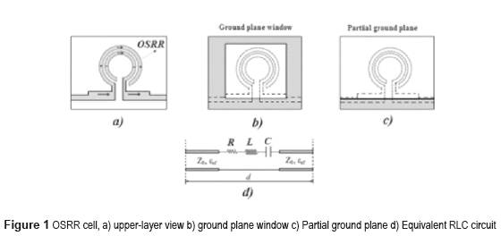
OSRR meta-material cells analysisThe OSRR cell shown in figure 1 is a modified version of the proposal presented in [6]. One of the rings bear a current flow that is fed by the main transmission line, whereas the other ring is fed by a displacement current that exists in the gaps between rings.
The circuit model is similar to that of an SRR cell; however, the transmission line is added in series, as shown in figure 1-b, with ground plane window and figure 1-c with partial ground plane. The bandwidth of the filter can be controlled by the length of the line sections between the OSRRs cell (d length in Figure 1-d), whereas the depth of the rejection band depends on the number of cells used for filter implementation [10]. The equivalent capacitance resulting from this configuration is four times larger than that of an SRR cell and its resonance frequency is the half and can be determined by equation (1).

Where Cs is the series capacitance of the upper and lower halves of the SRR structures analyzed in [6, 10, 11]. The inductance Ls can be approximated by that of a single ring with averaged radius ro and width c shown in figure 2, and determined by equation (2).

Where: 
And function B is defined as: 

With Sn and Jn being the nth-order Struve and Bessel functions. The new capacitance of an OSRR structure can be obtained from equation (3):

Where r0 is the ring's mean radius and Cpul is the capacitance per length unit, which can be calculated using equation (4):

Where F(k) can be calculated using equation (5) or (6):

Where k and k' is defined as:  and
and 
The results above are based upon the assumption of a lossless transmission line [10].
OSRR Band-pass filter Design and parametric studyAs mentioned above, the proposed approach is based on the guidelines described in [6, 10, 11]. Figure 1-c shows the proposed filter design, which stems from the OSRR cell model, eliminates the square windows etched at the bottom plane (Figure 1-b) and achieves optimization through a parametric analysis. The filter was implemented using three OSRR cells, and the structure of the circuit has been simulated and fabricated from a substrate material with εr = 3.5, tgδ = 0.0018, substrate thickness h = 1.524mm and copper thickness t = 17.5μm. This performs an operation comparable to a conventionally designed 3-pole filter.
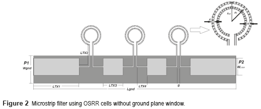
The characteristic impedance of the main transmission line is close to Z0 = 50Ω, and it should be considered that coupling is achieved through a variation of both width and length of the transmission line connecting each cell. In this study, the ground-plane windows (Figure 1-b) proposed in [10] have been removed, which completely eliminates copper from this section to minimize (up to a maximum extent) the capacitive-effect associated disturbances in the rings, as shown in figure 2. Eliminating the ground-plane window reduces the size of the filter due to the closer placement of the OSRR cells.
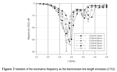
By using the design formulas (1-6) given in [6, 10, 11], it is possible to obtain a resonance frequency for the ring (f0 = 3.42GHz); with Ls = 7.58nH and C = 0.284pF for ring dimensions of c = 0.2mm, s = 0.3mm, rext = 2.0mm (Figure 2). However, this resonance frequency has been modified by enlarging the ring's junction lines towards (up to) the main transmission line. The rationale (the intended effect) behind applying such line enlargement is to induce an additional inductance that affects the resonance frequency given by (2). For this particular frequency, the filter's length (for N=3) is smaller than λ/2. Figure 3 shows simulated results for the effects derived from changing the filter's resonance frequency due to size variations applied to the lines that connect the rings to the main transmission line.
The present analysis on the effects of changing the length of the lines starts at 4.13 mm, which corresponds to the size of the lines that connect the cells to the main transmission line (LTX2 length in Figure 2). As observed in figure 3, the total resonance frequency of the filter decreases with an increase in the equivalent inductance associated to the size of the lines that connect the cells to the main transmission line.
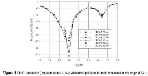
Figure 4 shows the simulated reflection coefficient results of the proposed filter for six different values of the main transmission line length (parameter LT1 in Figure 2). As observed in figure 4, the filter adaptation decreases with an increase in the size of the main transmission line. As a result, the reflection coefficient is sensitive to the main transmission line length, degrading the impedance adaptation when this value is not optimum.
Figure 5 shows the simulated reflection coefficients results (S11 and S22) along with the simulated transmissions coefficients results (S21) of the proposed filter for dimensions LTX1 = 8.83mm, LTX2 = 6.13mm, LTX3 = 3.87mm, LTX4 = 1.94mm, WLTX1 = 3.43mm, Wgnd = 5.48mm, Lgnd = 40.22mm, g = 0.5mm (Figure 2), as observed, the geometry was optimized through simulation.
Figure 6 shows the simulated transmission coefficients results (S21), using a ground plane window (6x7mm2) along with the simulated transmissions coefficients results (S21) of the proposed filter (partial ground plane) for the same dimensions related before. As observed, with respect to the ground plane windows version (Figure 1-b), the partial ground plane version (Figure 1-c) has the capacity to add transmission zero (4.6GHz) above transmission pole, which improves the rejection depth (8dB) without increasing the filter size.
Simulated and experimental results and discussion
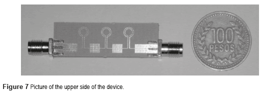
Once the geometry was optimized through simulation, the next step was to build the prototype for characterization purposes. Figure 7 shows a picture of the upper side of the device along with the corresponding SMA connectors (for the proposed partial ground plane filter).
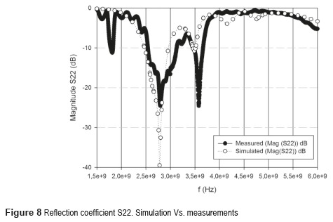
Figure 8 shows both the results of the experimental characterization of the prototype and the simulation results for parameter S22. It can be observed that the experimental measurements closely correspond, to a good extent, to the simulations for the proposed model. The resonance central frequency of the filter was f0 = 2.7GHz and the resulting bandwidth was approximately BW = 700MHz.
The adaptation of the filter to the Z0 impedance (Z0 = 50Ω) depends to a great extent on the width and length of the main transmission line (LTX1).
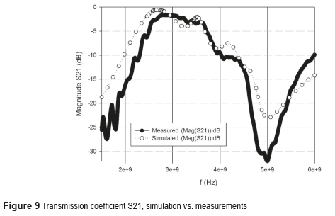
Figure 9 shows the measurement results of the prototype along with the simulation results for the transmission coefficient S21. The difference between the actual measurement in magnitude of parameter S21 and its simulation can be explained by considering the quality of the SMA connectors, as well as the N-to-SMA couplers that were necessary to accomplish the measurement process affecting de insertion losses. All measurements were taken using the network analyzer Rohde & Schwartz ZVL13.
In figures 8 and 9, a measured central frequency shift of about 200MHz can be observed when compared to the intended design frequency due to fabrication process.
ConclusionsA band-pass filter that uses OSRR cells and partial ground plane have been designed, optimized, implemented and characterized. Regarding the ground plane windows version, the partial ground plane version has the capacity to add transmission zero (4.6GHz) above the transmission pole, which improves the rejection depth (8dB) without increasing the filter size. The filter performance is similar to that of a conventional microstrip-technology 3-pole filter. To this end, the initial design parameters have been established analytically and the final geometry was optimized through simulation. The central resonance frequency and bandwidth obtained were 2.7GHz and 700MHz, respectively. The set of measurements taken for the prototype closely match the results obtained from simulating the proposed model. Finally, the dimensions of the proposed filter are as follows: 40.21mm*13.21mm compared to a conventional design with the same operation frequency whose dimensions are 107.12mm*21.19mm; which represents a size reduction of almost 60%.
References
1. V. Veselago. ''The electrodynamics of substances with simultaneously negative values of ε and µ''. Sov. Phyis. USPEKHI. Vol. 10. 1968. pp. 509-517. [ Links ]
2. V. Veselago, L. Braginsky, V. Shkloverand C. Hafner. ''Negative Refractive Index Materials''. Journal of Computational and Theoretical Nanoscience, Vol. 3. 2006. pp. 1-30. [ Links ]
3. J. Pendry, J. Holden, D. Robbins, W. Stewart. ''Magnetism from Conductors and Enhanced Nonlinear Phenomena''. IEEE Transactions on Microwave Theory and Techniques. Vol. 47. 1999. pp. 2075-2084. [ Links ]
4. J. Bonache. ''Metamaterials in Microstrip Technology for Filter Applications''. Antennas and Propagation Society International Symposium, IEEE. Vol. 1A. 2005. pp. 668-671. [ Links ]
5. J. Bonache. Filtros de microondas basados en metamateriales y en resonadores concentrados. PhD Thesis, Universidad Autónoma de Barcelona. Bellaterra, Spain. 2006. pp. 29-40. [ Links ]
6. J. Baena, J. Bonache, F. Martin, R. Sillero, F. Falcone, et al.''Equivalent-Circuit Models for Split-Ring Resonators and Complementary Split-Ring Resonators Coupled to Planar Transmission Lines''. IEEE Transactions on Microwave Theory and Techniques. Vol. 53. 2005. pp. 1451-1461. [ Links ]
7. K. Phani, S. Karthikeyan, A Compact and High Performance Band-Stop Filter Using open Complementary Split Ring Resonator. Proceedings of the National Conference on Communications (NCC). New Delhi, India. 2013. pp. 1-5. [ Links ]
8. J. Ruiz, J. Hinojosa, A. Alvarez. ''Microstrip notch filters based on open interconnected split ring resonators (OISRRs)''. Applied Physics A. Vol. 112. 2013. pp. 263-267. [ Links ]
9. L. Wang, X. Qi, F. Yong, Z. Bo. ''Electric Split-Ring Resonator Based on Double-Sided Parallel-Strip Line''. IEEE Antennas and Wireless Propagation Letters. Vol. 12. 2013. pp. 69-71. [ Links ] [ Links ]
11. R. Marqués, F. Mesa, J. Martel, F. Medina. ''Comparative Analysis of Edge- and Broadside-Coupled Split Ring Resonators for Metamaterial Design-Theory and Experiments''. IEEE Transactions on Antennas and Propagation. Vol. 51. 2003. pp. 2572-2581. [ Links ]
12. J. Ruiz, J. Hinojosa. ''Double-sided open split ring resonator for compact microstrip band-pass filter design''. IET Microw. Antennas Propag. Vol. 6. 2012. pp. 846-853. [ Links ]


