Services on Demand
Journal
Article
Indicators
-
 Cited by SciELO
 -
 Access statistics
Related links
-
 Cited by Google
 -
 Similars in
SciELO
 -
 Similars in Google
Share
Revista Facultad de Ingeniería Universidad de Antioquia
Print version ISSN 0120-6230
Rev.fac.ing.univ. Antioquia no.74 Medellín Jan./Mar. 2015
ARTÍCULO ORIGINAL
Experimental characterization of thermal hydraulic performance of louvered brazed plate fin heat exchangers
Caracterización térmico-hidraulica experimental del rendimiento de intercambiadores de placa y barras con aletas ventaneadas
John Turizo-Santos, Oscar Barros-Ballesteros, Armando Fontalvo-Lascano, Ricardo Vasquez-Padilla, Antonio Bula-Silvera*
Departamento de Ingeniería Mecánica, Universidad del Norte. Km 5 Vía Puerto Colombia. AA. 1569. Barranquilla, Colombia.
* Corresponding author: Antonio Bula Silvera, e-mail: abula@uninorte.edu.co
(Received April 12, 2014; accepted August 21, 2014)
Abstract
Louvered fins are commonly used in compact heat exchangers to increase the surface area, turbulence, and initiate new boundary layer growth required to improve the heat transfer performance without a significant increase in pressure drop compared with other fins. An experimental study on the air side heat transfer and pressure drop characteristics for a louvered fin with symmetrical patterns in brazed plate heat exchangers had been performed. Reynolds numbers ranged from 350 - 1270, based on the louver pitch while a constant 1.82 m3/h water flow was held. The heat transfer and pressure drop for the geometry tested was reported in terms of Colburn factor (j) and Fanning friction factor (f) as a function of the Reynolds number. The experimental results for j and f are in good agreement compared to regression models suggested for compact heat exchanger with louvered fin and flat tubes, obtaining a deviation of 5.48% and 5.39% respectively. Moreover, when compared to CFD analysis for the same geometry, an average deviation of 6.3% is obtained. Finally a regression model for j and f factors was attained based on the Reynolds number, presenting a deviation of 1.51% and 2.19% respectively.
Keywords: compact heat exchanger, louvered fins, Colburn factor, Fanning factor
Resumen
Las aletas tipo persianas se utilizan comúnmente en los intercambiadores de calor compactos para aumentar el área de superficie, la turbulencia, y producir una regeneración de la capa límite requerido para mejorar el rendimiento de transferencia de calor sin un aumento significativo en la caída de presión en comparación con otro tipo aletas. Un estudio experimental sobre la transferencia de calor y la caída de presión del lado del aire en aletas tipo persiana con patrón simétrico usada en intercambiadores de calor de placas soldadas, ha sido llevado a cabo. El números de Reynolds osciló entre 350 - 1270, basado en el pitch de la aleta, mientras se mantuvo un caudal de agua constante de 1,82 m3/h. La transferencia de calor y caída de presión para la geometría probada se presenta en términos del factor de Colburn (j) y el factor de fricción de Fanning (f) como función del número de Reynolds. Los resultados experimentales para j y f presentan un comportamiento acorde comparados con los modelos de regresión sugeridos para intercambiadores de calor compactos con aletas tipo persiana y tubos planos, presentando una desviación de 5,48 % y 5,39 % respectivamente. Por otra parte, cuando se compara con el análisis de CFD para la misma geometría, se obtiene una desviación media de 6,3%. Por último, un modelo de regresión para los factores j y f se logró con base en el número de Reynolds, presentando una desviación de 1,51 % y 2,19 % respectivamente.
Palabras clave: intercambiador de calor compacto, aletas tipo persiana, factor de Colburn, factor de Manning
Introduction
Compact heat exchangers are usually used in the automotive industry, air conditioning systems and cooling of electronic devices. The efficiency of these heat exchangers allows great energy savings. In order to increase the efficiency of such heat exchangers in terms of performance and size, various augmented surface designs have been developed to improve the air side heat transfer performance because it contributes close to 85% of the total heat transfer resistance [1-3]. The commonly used geometries include plain, wavy, offset, pin and louvered fins. The louvered fins are perhaps the most common modified elements in the design of compact heat exchangers, because they have the advantage of improving heat transfer without creating a disproportionate increase in pressure drop as other fins do. Louvered fins improve the performance of compact heat exchanger in terms of heat transfer capacity due to boundary layer breakup and later reattachment around the fins [2, 4]. Furthermore, the flow field for louvered fins depends on geometrical parameters such as the louver angle, fin pitch, louver pitch, and flow depth [4-6]. Therefore, these factors affect the thermal performance of the fin [7-10]. Large amount of research has been focused on evaluating the performance of this fin-type and proposed different general regression models based on the geometric parameters mentioned above and the Reynolds number to predict the behavior of louvered fins based on simulation and experimentation; these models have successfully become significant tools for designing compact heat exchangers in manufacturing.
The hydraulic and thermal behavior of louvered fins can be predicted from regression models developed experimentally for this type of fins. One model was proposed by [11], which includes the effect of geometrical parameters in louvered fin Colburn factor and fanning factor for compact heat exchangers with flat tubes. As shown in Eq. 1 and Eq. 2.

In this paper, a compact heat exchanger has been experimentally tested to obtain the regression models for thermal and hydraulic performance of a louvered fin with a specific geometry and symmetrical pattern, in terms of Colburn's factor (j) and Fanning's friction factor (f) as a function of the Reynolds number. Also, a comparison of the experimental results with some regression models presented in the literature for this type of fins and appropriate correlations are built for this specific case to describe the behavior of the fin.
Experimental setup
Test bench
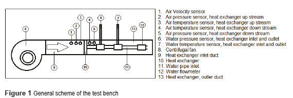
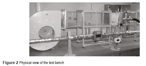
The device used to perform the experiments is shown in figures 1 and 2.
This test bench is characterized by two loops. The first one (open loop) moves air through a clear acrylic square duct, 0.3 m x 0.3 m, using a 660 N l/s variable speed centrifugal fan that takes air from the room with an average inlet temperature of 21°C ± 1°C and pumps it through the system. The first part of the duct allows a developed flow before entering the heat exchanger being tested. The second loop (closed loop) pumps water stored in a 0.7 m3 heating tank through a set of steel pipe with a nominal 40 mm diameter. The water temperature ranges between 35 °C and 85 °C. The water in the atmospheric tank is heated via a set of five 4 kW-electrical adjustable resistances. The variable speed centrifugal pump has a nominal flow capacity of 60 lt/min and a 10 m head. The variable speed is attained using a variable frequency drive which allows evaluating the behavior of the exchanger at different controllable flow conditions in both loops. This paper focuses on the heat transfer characteristics and its calculation on the air side This paper focus on the air side loop. These variable frequency drives operate at frequencies ranging from 5Hz to 60Hz, representing Reynolds numbers between 350 and 1270 on the air side for the geometry tested.
InstrumentationEight (8) pre-calibrated 4-wire RTDs are used for measuring temperatures in the test bench. They are used to measure: water inlet and outlet temperature at the heat exchanger; air inlet and outlet temperature at the heat exchanger; water outlet at the tank, and three for the wall temperature of the exchanger. The pressure drop across the heat exchanger was measured using four pressure transducers calibrated with an accuracy of 0.2% for the full scale. They were located at the inlet and outlet of the water and air sides The pressure drop across the heat exchanger was measured using four pressure transducers calibrated with an accuracy of 0.2% of full scale located at the inlet and outlet of the heat exchanger in loops, water and air. The velocity of the air is measured using an air velocity transmitter with an accuracy of 1.5%, and the hot water flow is measured using a flow transmitter with an accuracy of 2%, located at the inlet of the heat exchanger tested.
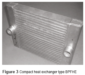
Heat exchanger testedThe heat exchanger tested is typical for processes involving water and air as working fluids known as BPFHE (Brazed Plate Fin Heat Exchanger) type, which is shown in Fig. 3
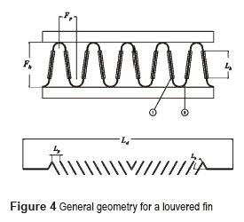
The heat exchanger dimensions are 300 mm height, 300 mm length, 50 mm width. . It consists of 16 sections of louvered fins and 14 rectangular sections that conduct hot water. The dimensions are 300 mm x 300 mm x 50 mm. It consists of 16 sections of louvered fins and 14 rectangular sections, where hot water circulates. These sections are arranged in an interleaved pattern, with exception of those located in the central part, where two louvered fin sections are located consecutively. The louvered fin geometry used is presented in Fig. 4 and Table 1.
Test Conditions
For the analysis of the experimental results, the heat exchanger was taken into steady-state condition. The test was performed for Reynolds numbers ranging from 350 to 1270 based on the louvered fin pitch and maximum speed of air, for a fixed water flow of 1.30 l/min. Furthermore, the temperature at the heat exchanger inlet was set at 80°C ± 1°C for water, and 21°C ± 1°C for air. Twenty one (21) experimental conditions were tested with 4 replicates.
Identification of Performance ParametersTo determine the heat transfer coefficient for the air side, a calculation methodology similar to that presented by [11] was developed. This involves calculating the heat transfer rate required, which can be expressed according to Eq. 3,

where  are heat transfer rate from the water side and the air, respectively, and can be calculated using Eq. 4 and Eq. 5 as follows:

Using the effectiveness-NTU method, the equations developed by [12] for unmixed fluids in both cases are used. For efficiency, Eq. 6 is presented,

The definition is presented in Eq. 7.

The thermal energy transport capacity is presented in Eq. 8,

Then, the overall heat transfer coefficient for the heat exchanger tested can be obtained from Eq. 9,

From the overall heat transfer coefficient calculated in Eq. 9, it is possible to determine the convective coefficient for the air side according to Eq. 10,

In Eq. 10, it is necessary to determine the convective heat transfer coefficient from the water side. The Gnielinski equation, presented in Eq. 11 for turbulent flow is used,

From Nusselt number definition presented in Eq. 12, the convective heat transfer coefficient is obtained.

Another important parameter in the calculations is the surface effectiveness and the fin efficiency of the area of interest, ηa and ηf respectively. In our case, the area of interest corresponds to the louvered fins. The tubes and fins efficiency can be obtained from the definition presented in Eq. 13,

And the efficiency of the louvered fins is attained from Eq. 14,

Where m' and l' are obtained from Eq. 15 and Eq. 16 respectively,

Taking into consideration that air is considered as an incompressible fluid and its properties are constant according to the average air temperature, the Colburn factor j and Fanning factor f, which describe the heat transfer and pressure drop behavior respectively for fins, can be calculated according to Eq. 17 and Eq. 18.

Where Reynolds is calculated according to the definition presented in Eq. 19,

The pressure drop coefficients for the heat exchanger at the entrance, Kc, and at the exit, Ke, are calculated considering a free-flow to frontal air side area ratio, σa, of 0.6. The values are 1.05 and 0.32 considering the graph shown [13]. Considering the instrument errors, property uncertainties and geometry tolerance, the uncertainties for the heat transfer coefficients and pressure drop are ±12.8% and ±10.7%, respectively.
Test Results and Discussion
Behavior of the heat transfer coefficient for the air side as a function of Reynolds number
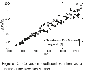
The external forced convective heat transfer coefficient for the fins is one of the main parameters during the design of compact heat exchangers. Figure 5 shows the heat transfer coefficient variation for Reynolds ranging from 350 to 1270. Such distribution has an increasing trend typical of the phenomenon.
Fig. 5 also presents the comparison with the results reported by [11] for a geometry similar to this case. Despite the geometric differences, the response for both fins is quite similar for the Reynolds number range studied. The louver fin geometry used for comparison is presented in Table 2.
Behavior of Colburn factor and Fanning factor respect to the Reynolds number
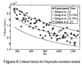
Figure 6 shows the variation of the Colburn's factor experimentally obtained as a function of Reynolds number, as well as the value obtained using the correlation presented by [11].
It is noticed that the data are within a ±10% range from the model. Furthermore, these results are also compared with those obtained by [13] for the experimental range evaluated from CFD analyzes performed in the same geometry, obtaining an average error of 6.3%. The experimental data has an average percentage deviation of 5.48% with respect to the regression model proposed by [11].
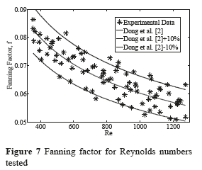
Figure 7 shows the results obtained for the friction coefficient. The results are compared with the regression model proposed by [11] for Fanning and Colburn factors. These results are comprised between bands located at ±10% of the value proposed by [11]
The results show a good prediction of the behavior of the fanning factor regression model, obtaining average percentage deviation of 5.39% from the value suggested by the model.
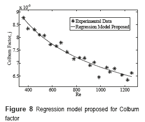
Correlations proposed for Colburn's factor and Fanning's factor with respect to the Reynolds numberThe correlations are obtained using 21 experimental conditions each one with 4 replicates, with a series of 100 experimental data for each replica. The correlations for j and f are shown in Eq. 20 and Eq. 21 respectively,

Figure 8 shows the experimental results for Colburn factor compared with the regression model proposed to this louvered fin geometry. For this case, a percentage average deviation of 1.51% was obtained.
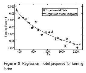
Moreover, Figure 9 shows the experimental results compared with the regression model proposed for fanning factor. For this case, we obtained a percentage average deviation of 2.19%.
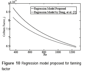
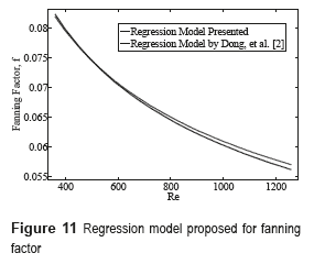
Figure 10 and Figure 11 show a comparison between the regression model proposed in this work and the regression model given by [11] for the geometry considered in the paper. They showed a good agreement.
ConclusionsA BPFHE compact heat exchanger with louvered fins on the air side has been studied in this paper. The thermo hydraulic performance of the heat exchanger was measured and compared with regression models developed for this type of fins depending on its geometrical configuration, and also compared with the results obtained from CFD analysis for the same geometry. In the range of Reynolds number from 350 to 1270, there is a good agreement between the experimental results presented in this paper when compared [11], presenting an average error of 5.48% and 5.39% for the Colburn factor and Fanning factor respectively.
AcknowledgementsThe authors gratefully acknowledge the financial support from COLCIENCIAS, as well as the important contribution from Universidad del Norte and ICER Ltda.
References
1. Lyman, R. Stephan, K. Thole, L. Zhang, S. Memory. ''Scaling of heat transfer coefficients along louvered fins''. Experimental Thermal and Fluid Science. Vol. 26. 2002. pp. 547-563. [ Links ]
2. C. Davenport. Heat transfer and fluid flow in louvered Triangular ducts. PhD Thesis, Lanchester Polytechnic. Coventry, UK. 1980. pp. 38. [ Links ]
3. J. Mao, H. Chena, H. Jia, Y. Wang, H. Hu. ''Effect of air-side flow maldistribution on thermal-hydraulic performance of the multi-louvered fin and tube heat exchanger''. International Journal of Thermal Sciences. Vol. 73. 2013. pp. 46-57. [ Links ]
4. C. Davenport. ''Correlation for heat transfer and friction characteristics of louvered fin''. AICHE Symposium Series. Vol. 79. 1983. pp. 19-27. [ Links ]
5. A. Achaichia, T. Cowell. A Finite Difference Analysis of Fully Developed Periodic Laminar Flow in Inclined Louver Arrays. Proceedings of the 2nd UK National Heat Transfer Conference, Glasgow, UK. 1988. pp. 883-898. [ Links ]
6. A. Vaisi, M. Esmaeilpour, H. Taherian. ''Experimental investigation of geometry effects on the performance of a compact louvered heat exchanger''. Applied Thermal Engineering. Vol. 31. 2001. pp. 3337-3346. [ Links ]
7. Y. Chang, C. Wang. ''Air Side Performance of Brazed Aluminum Heat Exchangers''. Journal of Enhanced Heat Transfer. Vol. 3. 1996. pp. 15-28. [ Links ]
8. X. Zhang, D. Tafti. ''Flow efficiency in multi-louvered fins''. International Journal of Heat and Mass Transfer. Vol. 46. 2003. pp. 1737-1750. [ Links ]
9. D. Antonijevic. ''An engineering procedure for air side performance evaluation of flat tube heat exchangers with louvered fins''. Heat Mass Transfer. Vol. 49. 2013. pp. 117-127. [ Links ]
10. H. Kang, H. Cho, J. Kim, A. Jacobi. ''Air-Side Heat Transfer Performance of Louver Fin and Multitube Heat Exchanger for Direct Methanol Fuel Cell Cooling Application''. Journal of Fuel Cell Science and Technology. Vol. 11. 2014. [ Links ]
11. J. Dong, J. Chen, Z. Chen, W. Zhang, Y. Zhou. ''Heat transfer and pressure drop correlations for the multi-louvered fin compact heat exchangers''. Energy Conversion and Management. Vol. 48. 2007. pp. 1506-1515. [ Links ]
12. Engineering Sciences Data Unit. Effectiveness-NTU relations for the design and performance evaluation of two-stream heat exchangers. Technical Report ESDU 86018 with amendment, London ESDU International plc. London, UK. 1991. pp. 92-107. [ Links ]
13. A. Kays, A. London. Compact heat exchangers. 3rd ed. Ed. McGraw-Hill. New York, USA. 1984. pp. 335. [ Links ]


