Services on Demand
Journal
Article
Indicators
-
 Cited by SciELO
 -
 Access statistics
Related links
-
 Cited by Google
 -
 Similars in
SciELO
 -
 Similars in Google
Share
Revista Facultad de Ingeniería Universidad de Antioquia
Print version ISSN 0120-6230
Rev.fac.ing.univ. Antioquia no.75 Medellín Apr./June 2015
https://doi.org/10.17533/udea.redin.n75a07
ARTÍCULO ORIGINAL
DOI: 10.17533/udea.redin.n75a07
Parameter estimation method for induction machines using instantaneous voltage and current measurements
Método para la estimación paramétrica de máquinas de inducción utilizando medidas de tensiones y corrientes instantáneas
Johnny Wladimir Rengifo-Santana1*, Joseph Benzaquen-Suñe1, José Manuel Aller-Castro1,3, Alexander Alfredo Bueno-Montilla1, José Alex Restrepo-Zambrano2
1 Departamento de Conversión y Transporte de Energía, Universidad Simón Bolívar. Valle de Sartenejas, Municipio Baruta, Estado Miranda 1080. Apartado 8900. Caracas, Venezuela.
2 Departamento de Electrónica y Circuitos, Universidad Simón Bolívar. Valle de Sartenejas, Municipio Baruta, Estado Miranda 1080. Apartado 8900. Caracas, Venezuela.
3 Grupo de Investigación en Energías, Universidad Politécnica Salesiana. Calle Vieja 12-30 y Elia Luit. C.P. 010106. Cuenca, Ecuador.
* Corresponding author: Johnny Wladimir Rengifo Santana, e-mail: jwrengifo@usb.ve
(Received October 08, 2013; accepted March 26, 2015)
Abstract
This paper proposes an off-line method to determine the electrical parameters of an induction machine based on two instantaneous indicators (impedance and power). The method uses the induction machine start-up voltage and current measurements. Also, the proposed method employs a space vector dynamic model of the induction machine referred to the fixed stator reference frame. This model allows the representation of the instantaneous indicators in terms of the machine electrical parameters. An error function is defined using the indicators obtained from the measurements, versus the corresponding derived from the dynamic model of the machine. The estimated parameters are obtained by minimizing this error function by means of a constrained nonlinear optimization algorithm. The effectiveness of the proposed method was experimentally validated. The results from the model using the estimated parameters fit the experimental data sets with average error below 5%.
Keywords: induction machines, parameter estimation, rotating machine transient, nonlinear estimation
Resumen
En este trabajo se propone un método fuera de línea para determinar los parámetros eléctricos de una máquina de inducción basados en dos indicadores instantáneos (impedancia y potencia). El método utiliza las medidas de tensión y corriente durante el arranque de una máquina de inducción. El método propuesto emplea un modelo vectorial dinámico referido al sistema de coordenadas del estator. Este modelo permite la representación de los indicadores instantáneos en términos de los parámetros eléctricos de la máquina. Se construye una función de costo utilizando los indicadores obtenidos a partir de las medidas de tensión y corriente, versus los correspondientes indicadores calculados a partir del modelo dinámico. Los parámetros estimados se obtienen mediante la minimización de la función de costo, utilizando un algoritmo de optimización no lineal con restricciones. La eficacia del método propuesto fue validada experimentalmente.
Palabras clave: máquinas de inducción, estimación de parámetros, transitorios de máquinas rotativas, estimación no lineal
Introduction
Induction machines are widely used in industrial applications mainly for their ruggedness, reliability, low cost and maintenance. The parameter estimation for high power induction machines (rated power ≥200kW) is useful in different applications, e.g.: energy efficiency evaluation, start-up's time and current estimation, protective device coordination analysis, steady state and transient studies in the power systems.
The simplest method for parameter estimation is the classical no-load and locked-rotor tests of an induction motor [1]. An improvement over this is to use the manufacturer's data to determine the National Electrical Manufacturers Association (NEMA) design induction motor parameters [2].
On the other hand, using the linear equivalent circuit of the electromechanical converter in balanced, sinusoidal and steady state operation, an impedance function can be defined. This input impedance is a function of the equivalent circuit parameters, the electric frequency and the slip. Applying the same simplifying hypothesis used in the estimation of the transformer model parameters, an analogous method can be used for induction machines. The transformer based parameter estimation method gives an initial, close and feasible solution.
A second approach is using an error function that takes the squared mismatch between the measured impedance and the one obtained from the machine model. This error function uses the values in at least three independent operating points (i.e. no-load, locked-rotor, and any other operating slip). The absolute minimization of this error function results in better parameter estimation for this set of operating points. In order to acquire a physically feasible set of parameters, it is necessary to solve the optimization problem with box type constrains. The parameters restrictions upper and lower bounds are set using a common range in per unit.
There is a nonlinear relation between the machine parameters and the electrical frequency, described by the input impedance. The instantaneous time response has a linear relation between parameters and state variables when assuming a constant or quasi-constant rotor speed. [3-6] proposed a real time estimation of the parameters using linear regression based on the second and third time derivatives of the stator currents and second time derivatives of the stator voltage. This identification method uses the quasi-stationary induction machine equations and considers the core saturation.
Recent works follow other approaches to solve the induction machine parameters estimation problem. In [7] is proposed the use of adaptive linear neuron (ADALINE) for online electric parameter identification of the induction machine at standstill. [8, 9] proposed an offline method to estimate the parameters of multiphase induction machines with distributed windings. [10] submitted a method applicable to a double cage induction motor based on the manufacturer's data using a constrained minimization. [11] introduced a method using steady state voltage, currents, power and speed measurements. Meanwhile, [12] proposed a technique to estimate parameters from a distributed more accurate model obtained using a 3D magnetic equivalent circuit analysis. [13] uses a lumped parameters model including saturation effects and core losses recovered with magnetic field analysis of the induction machine.
The rotor resistance value is bound to change due to temperature variations during the machine's normal operation, affecting the speed control performance. In this sense, many authors have suggested several solutions to solve it [14-17].
In addition, [18] shows a methodology to estimate the induction machine parameters using a VSI PWM to inject low and high frequencies to estimate the rotor resistance, leakage and magnetizing inductances while maintaining the motor at standstill. [19] provided a solution to obtain the parameters using simulated data, through the minimization of the errors between the model's dynamic performance and these data; genetic algorithms were used to minimize the errors. However, the use of genetic algorithm implies a large computational cost [20]. Furthermore, [21] proposed a parameter estimation method based on a curve fitting technique of the stator current response and the dynamic model of the machine. This method was validated using time-harmonic finite-element analysis for a triple cage induction machine and assuming the stator resistance as a known parameter. More recently, [22] proposed the use of iterative calculations to minimize the difference between the losses calculated with the model and that by using finite-element analysis (FEA).
The linear regression can be applied for constant or quasi constant rotor speed operation. Since a nonlinear regression is proposed in this paper, together with the use of the instantaneous impedance or power
 during the induction machine start-up, in this case, the constant or quasi-constant rotor speed restriction is released. Also, the instantaneous impedance or power is adjusted in a least squares sense, to the instantaneous values of the impedance or power calculated with the measured stator voltage and currents. The proposed method requires the instantaneous mechanical speed, either estimated or measured [23-26]. The main objective of this work is to obtain the induction machine parameters in industrial environments, given that conventional and standard tests are difficult to apply in field conditions [1]. The instantaneous impedance or power equation is derived using the induction machine model in the fixed stator reference frame. Each impedance or power value obtained from measured variables is compared with the same one obtained from the dynamic model and used to compute the least square error function. The machine start-up is used to produce several groups of independent (uncorrelated) data sets in one test. The proposed method requires a first order derivative of the stator current, instead of the higher order derivatives required by the quasi-static approach [3-6]. Additionally, with the elimination of the quasi-static restriction, the method can be applied under load transients, such as the machine start-up. Finally, since the proposed method requires only stator and current measurements, it results convenient for industrial environments. A previous approach was presented in [26] using simulation and the angular speed estimation obtained from electric torque during no-load start-up. In this paper, an experimental validation of the proposed method is included, using current spectral speed estimation in a start-up [23, 24, 27-29].
Induction machine model
The space vector model of the induction machine in the fixed stator reference frame αβ, can be represented in Eqs. (1-3) [30],


where, p=d/dt, the superscript * stands for the complex conjugated, and
and are the stator and rotor current space vectors,
 is the stator voltage space vector. The parameters required by this model are the stator resistance Rs, the stator inductance Lr, the rotor resistance Rr, the rotor inductance Lr, the coupling stator-rotor inductance M, the number of pole pairs npand the moment of inertia J, Tmis the mechanical load torque, and ωmis the mechanical angular speed. The coordinate transformation αβused in this paper is in Eq. (4),

Parameter estimation
Stator indicators
The proposed method for estimating the parameters for the induction machine's equivalent circuit is based on the instantaneous stator input indicators, such as, the instantaneous power or impedance. The machine model Eqs. (1-3) is expressed as function of the stator and rotor currents. Nevertheless, the rotor current is not a measurable variable in a squirrel cage induction motor. The rotor current expressed as function of the stator flux linkage is presented in Eqs. (5) and (6),


Replacing Eq.(6) in (1) and (2), the expressions (7) and (8) are obtained,


where,. Finally, the instantaneous stator indicators are found from Eqs.(7) and (8) as Eqs. (9) and (10),


The instantaneous stator input indicators  or
or depend on the stator voltage space vector, stator current space vector, flux linkage, angular speed and the machine parameters. The instantaneous stator voltage and current are measured directly from the machine terminals. Simultaneously, both the stator current derivative and flux linkage can be estimated from the stator voltage and current space vectors. Flux linkage
 shown in (Eq. 11), is determined by integrating Eq. (7),

while the current space vector derivative can be numerically calculated from the current space vector
  . Finally, to calculate the instantaneous stator input indicators is necessary to know the angular speed of the induction machine, obtained from direct measurements or from a speed estimator.
Optimization problem
The cost function Ψused for the parameter estimation compares each measurement of the instantaneous input indicator with the one calculated using the machine model developed in Eq.(9) or (10)
 . The function takes the square difference between the N values acquired, as depicted Eqs. (12) and (13).

where,

the instantaneous input indicators is obtained using (9) or (10) , and N is the number of recorded measurements. The minimization of the cost function produces the optimal set of parameters.
The stator space vectors and
and require four independent measurements, they are two line to line voltages, and two line currents [31]; as is presented in Eqs. (14) and (15),


where,vab + vbc + vca = 0and ia + ib + ic =0.
Experimental results
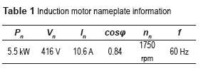
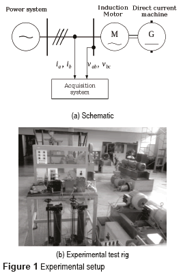
The proposed method's experimental validation has been carried out for an induction motor, with nameplate information presented in Table 1. The acquisition system employs four channels with 18 kHz sampling frequency per channel, allowing the measurement of two stator line-line voltages and two stator line currents. Figure 1 shows the experimental setup.
The experimental test performed consisted in a direct startup of the induction machine with a three-phase sinusoidal voltage source at rated frequency. To emulate the start-up time of the induction machine with a rated power within the range under a study (≥200kW), the supply voltage was reduced to 0.25Vn.
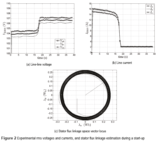
The instantaneous rmsvoltages and currents are shown in Figure 2. The total start-up time is around 18 s. During the start-up, there was a drop near 2% of the operating voltage, due to the large stator currents and to the short circuit level of the power supply. The machine stator resistance was 0.033 pu, measured directly from the machine terminals. The stator flux linkage was calculated with and is shown in Figure 2c.
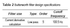
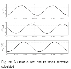
Figure 3a presents the steady state stator current's spectrum showing the signal harmonic distortion. To calculate the current derivative  the stator current high frequency harmonics are first filtered out using a low pass Butterworth filter [32], and shown in Table 2. Filters with coefficients were also used for processing voltage and current signals to avoid delays between signals. Figure 3 displays the measured stator current, the filtered one; and the current derivative calculated from the filtered current.
The numerical approximation used to determine the stator current derivative is presented in Eq. (16),

where,Tsis the sampling time.
Sensorless speed estimation
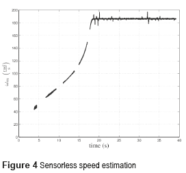
The parameter estimation method proposed in this paper requires the mechanical speed. This paper uses a sensorless speed estimation based on the information contained in the stator line current spectrum. The speed estimation was accomplished by analyzing the harmonics produced by the rotor slots and their trace in stator current [23, 24, 29]. The resulting mechanical speed is presented in Figure 4. The gaps presented in this figure were produced by the filters used in the estimation algorithm. However, the presence of these gaps does not preclude the use of the proposed parameter estimation method.
Experimental validation
The induction machine parameters are obtained by a nonlinear constrained optimization with Ψas objective function, presented in Eq. (17). The restrictions are adjusted as a set of inequality equations using typical parameter range limits in per unit system. The optimization was accomplished by applying the interior point algorithm [33].

where, xz=[Lσs Lσr M Rr]t, lb=[0.005 0.005 10.005]t is the lower bounds vector, ub=[0.1 0.1 3.5 0.1]tis the upper bounds vector.
Table 3 shows the results for the case under study, where the stator resistance Rsis assumed to be known. The results are expressed in per unit, and the rated values (Table 1) were taken as bases.
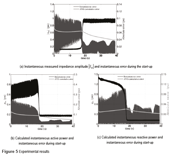
The results show that the proposed methodology allows an accurate fitting of the machine model when compared with the experimental response. In addition, the average error per measurement is approximately 4.76%. Figure 5a displays the input impedance magnitude along the complete start-up of the motor, and the absolute error during time segment. Figures 5b and 5c display the input active and reactive power pin(t)and qin(t)during the machine's start-up, the respective absolute error and their average (AVG) error. The estimated parameters give a representation of the induction machine start-up, especially in steady state, in which the absolute error is under 4%. An additional test for evaluating accuracy of the estimation is using the value of the rotor resistance, obtained with a three-phase locked-rotor impedance test at reduced frequency (15Hz)[1]. This additional test yields a rotor resistance of 0.0184 pu, versus 0.0181 pu obtained with the proposed method. This parameter is the most important in the induction machine's energy conversion exchange behavior and also is the most complex to measure.Conclusions
In this work, a method to estimate the parameters of an induction machine had been proposed, using noninvasive voltage and current measurements. Instantaneous impedance and power were used as error indicators in the cost function. The proposed method was experimentally validated in a squirrel cage machine starting on load condition. The average error for the indicator mismatch for each measurement was less than 5%. This method represents a good alternative to achieve full and precise parameter estimation in industrial environments. The parameter set obtained is independent of the indicator impedance or power used. This method is robust, powerful tool and easy to implement for off-line parameter estimation. The estimated parameters are highly dependent on the measurement precision of the stator resistance. However, a precise measurement of this resistance can be obtained with the induction motor at stand still. The main difficulty of the method, to get good accuracy, rests in obtaining the stator current derivative. Finally, the method does not need slow variations of the angular speed.
Acknowledgment
This work was supported by FONACIT-Venezuela under project Number 201100348.
References
1. IEEE. IEEE standard test procedure for polyphase induction motors and generators. IEEE Std 112. 2004. pp. 1-79. [ Links ]
2. M. Haque. ''Determination of NEMA design induction motors parameters from manufacturer data''. Energy Conversion, Transactions on. Vol. 23. 2008. pp. 997-1004. [ Links ]
3. C. Moons, B. Moor. ''Parameter identification of induction motor drives''. Automatica. Vol. 31. 1995. pp. 1137-1147. [ Links ]
4. J. Stephan, M. Bodson, J. Chiasson. ''Real-time estimation of the parameters and fluxes of induction motors''. Industry Applications, IEEE Transactions on. Vol. 30. 1994. pp. 746-759. [ Links ]
5. M. Cirrincione, M. Pucci, G. Cirrincione, G. Capolino. ''A new experimental application of least-squares techniques for the estimation of the induction motor parameters''. Industry Applications, IEEE Transactions on. Vol. 39. 2003. pp. 1247-1256. [ Links ]
6. M. Cirrincione, M. Pucci, G. Cirrincione, G. Capolino. ''Constrained minimization for parameter estimation of induction motors in saturated and unsaturated conditions''. Industrial Electronics, IEEE Transaction on. Vol. 52. 2005. pp. 1391-1402. [ Links ]
7. A. Bechouche, H. Sediki, D. Abdeslam, S. Haddad. ''A novel method for identifying parameters of induction motors at standstill using ADALINE''. Energy Conversion, IEEE Transactions on. Vol. 27. 2012. pp. 105-116. [ Links ]
8. A. Yepes, J. Riveros, J. Doval, F. Barrero, O. Lopez, B. Bogado, M. Jones, E. Levi. ''Parameter identification of multiphase induction machines with distributed windings - part 1: Sinusoidal excitation methods''. Energy Conversion, Transactions on. Vol. 27. 2012. pp. 1056-1066. [ Links ]
9. A. Riveros, A. Yepes, F. Barrero, J. Doval, B. Bogado, O. Lopez, M. Jones, E. Levi. ''Parameter identification of multiphase induction machines with distributed windings - part 2: Time-domain techniques''. Energy Conversion, IEEE Transactions on. Vol. 27. 2012. pp. 1067-1077. [ Links ]
10. J. Pedra. ''On the determination of induction motor parameters from manufacturer data for electromagnetic transient programs''. Power Systems, Transactions on. Vol. 23. 2008. pp. 1709-1718. [ Links ]
11. E. Laroche, M. Boutayeb. ''Identification of induction motor in sinusoidal mode''. Energy Conversion, IEEE Transactions on. Vol. 25. 2010. pp. 11-19. [ Links ]
12. M. Amrhein, P. Krein. ''Induction machine modeling approach based on 3-D magnetic equivalent circuit framework''. Energy Conversion, IEEE Transactions on. Vol. 25. 2010. pp. 339-347. [ Links ]
13.S. Raptis, A. Kladas, J. Tegopoulos. ''Accurate induction motor estimator based on magnetic field analysis''. Magnetics, IEEE Transactions on. Vol. 44. 2008. pp. 1574-1577. [ Links ]
14. G. Kenné, R. Simo, F. Lamnabhi, A. Arzandé, J. Vannier. ''An online simplified rotor resistance estimator for induction motors''. Control System Technology, IEEE Transactions on. Vol. 18. 2010. pp. 1188-1194. [ Links ]
15. C. Kral, T. Habetler, R. Harley, F. Pirker, G. Pascoli, H. Oberguggenberger, C. Fenz. ''Rotor temperature estimation of squirrel cage induction motors by means of a combined scheme of parameter estimation and a thermal equivalent model''. Industry Applications, IEEE Transactions on. Vol. 40. 2004. pp. 1049-1057. [ Links ]
16. A. Proca, A. Keyhani. ''Sliding-mode flux observer with online rotor parameter estimation for induction motors''. Industrial Electronics, IEEE Transactions on. Vol. 54. 2007. pp. 716-723. [ Links ]
17. S. Rao, M. Buss, V. Utkin. ''Simultaneous state and parameter estimation in induction motors using first- and second-order sliding modes''. Industrial Electronics, IEEE Transactions on. Vol. 56. 2009. pp. 3369-3376. [ Links ]
18. L. Peretti, M. Zigliotto. ''Automatic procedure for induction motor parameter estimation at standstill''. IET Electric Power Applications. Vol. 6. 2012. pp. 214-224. [ Links ]
19. K. Huang, Q. Wu, D. Turner. ''Effective identification of induction motor parameters based on fewer measurements''. Energy Conversion, IEEE Transactions on. Vol. 17. 2002. pp. 55-60. [ Links ]
20. B. Abdelhadi, A. Benoudjit, N. Nait. ''Application of generic algorithm with a novel adaptive scheme for the identification of induction machine parameters''. Energy Conversion, IEEE Transactions on. Vol. 20. 2005. pp. 284-291. [ Links ]
21. H. Khang, A. Arkkio. ''Parameter estimation for deep-bar induction motor''. IET Electric Power Applications. Vol. 6. 2012. pp. 133-142. [ Links ]
22. K. Yamazaki, A. Suzuki, M. Ohto, T. Takakura. ''Circuit parameters determination involving stray load loss and harmonic torques for high-speed induction motors fed by inverters''. Energy Conversion, IEEE Transactions on. Vol. 28. 2013. pp. 154-163. [ Links ]
23. J. Aller, J. Restrepo, A. Bueno, M. Gimenez, G. Pesse. Squirrel cage induction machine model for the analysis of sensorless speed measurement methods. Proceedings of the 2nd IEEE International Caracas Conference on Devices, Circuits and Systems. Caracas, Venezuela. 1998. pp. 243-248. [ Links ]
24. J. Aller, T. Habetler, R. Harley, R. Tallam, S. Lee. ''Sensorless speed measurement of AC machines using instantaneous analytic wavelet transforms''. Industry Applications, IEEE Transactions on. Vol. 38. 2002. pp. 1344-1350. [ Links ]
25. J. Aller, J. Restrepo, A. Bueno, M. Giménez, V. Guzmán. ''Induction machine model for sensorless speed measurement systems''. IEEE Power Engineering Review. Vol. 28. 1998. pp. 53-54. [ Links ]
26. J. Rengifo, J. Aller, A. Bueno, J. Viola, J. Restrepo. Parameter estimation method for induction machines using the instantaneous impedance during a dynamic start-up. Proceedings of the VI Andean Region International Conference (ANDESCON). Cuenca, Ecuador. 2012. pp. 11-14. [ Links ]
27. J. Cameron, W. Thomson, A. Dow. ''Vibration and current monitoring for detecting airgap eccentricity in large induction motors''. IEE Proceedings B Electric Power Applications. Vol. 133. 1986. pp. 155-163. [ Links ]
28. J. Restrepo, P. Bowler. Analysis of induction machine slot harmonics in the TF domain. Proceedings of the 1st IEEE International Caracas Conference on Devices, Circuits and Systems. Caracas, Venezuela. 1995. pp. 127-130. [ Links ]
29. S. Mallat. A wavelet tour of signal processing. 3rd ed. Ed. Academic Press. Boston, USA. 1999. pp. 820. [ Links ]
30. A. Trzynadlowski, The field orientation principle in control of induction motors. 1st ed. Ed. Kluwer Academic Pub. New York, USA. 1994. pp. 255. [ Links ]
31. J. Aller, A. Bueno, T. Pagá. ''Power system analysis using space vector transformation''. Power System, IEEE Transactions on. Vol. 17. 2002. pp. 957-965. [ Links ]
32. L. Rabiner, B. Gold. Theory and application of digital signal processing. 1st ed. Ed. Prentice-Hall, Inc. New Jersey, USA. 1975. pp. 777. [ Links ]
33. R. Byrd, M. Hribar, J. Nocedal. ''An interior point algorithm for large-scale nonlinear programming''. SIAM Journal on Optimization. Vol. 9. 1999. pp. 877-900. [ Links ]


