Serviços Personalizados
Journal
Artigo
Indicadores
-
 Citado por SciELO
 -
 Acessos
Links relacionados
-
 Citado por Google
 -
 Similares em
SciELO
 -
 Similares em Google
Compartilhar
Revista Facultad de Ingeniería Universidad de Antioquia
versão impressa ISSN 0120-6230
Rev.fac.ing.univ. Antioquia no.77 Medellín out./dez. 2015
https://doi.org/10.17533/udea.redin.n77a17
ARTÍCULO ORIGINAL
DOI: 10.17533/udea.redin.n77a17
An optimal high thermal conductive graphite microchannel for electronic device cooling
Microcanal óptimo de grafito de alta conductividad térmica para el enfriamiento de componentes microelectrónicos
Jorge Mario Cruz-Duarte*, Iván Mauricio Amaya-Contreras, Carlos Rodrigo Correa-Cely
Escuela de Ingenierías Eléctrica, Electrónica y de Telecomunicaciones, Universidad Industrial de Santander. Carrera 27 Calle 9. A. A. 678. Bucaramanga, Santander.
* Corresponding author: Jorge Mario Cruz Duarte, e–mail: jorge.cruz1@correo.uis.edu.co
DOI: 10.17533/udea.redin.n77a17
ISSN 0120–6230
e–ISSN 2422–2844
(Received April 27, 2015; accepted September 07, 2015)
ABSTRACT
This article describes the design of an optimal rectangular microchannel made of a high thermal conductive graphite (HTCG). For simulating the proposed microchannel heat sink, the total resistance model and the entropy generation minimization criterion were used. For solving the optimization problem, the unified particle swarm optimization algorithm (UPSO), was used. Results showed a marked effect of using this high thermal conductor when compared to traditional materials, such as aluminum, and while using air and ammonia gas as the working fluids. It is also reported the relative effect of the constriction, convective and fluid thermal resistances on the overall equivalent thermal resistance. As a demonstrative example when changing the nature of the coolant, a titanium dioxide nanofluid was selected. It was found that the Nusselt number is perceptibly lower, when the coolant is a nanofluid and the material for the making of the microchannel is an HTCG.
Keywords: Microchannels, heat sinks, minimum entropy generation, unified particle swarm optimization, high thermal conductive graphite
RESUMEN
Este artículo describe el diseño de un microcanal rectangular óptimo, construido con grafito de alta conductividad térmica (HTCG). Para simular el disipador de microcanales propuesto se utilizó el modelo de resistencia térmica total y el criterio de minimización de la generación de entropía. Para solucionar el problema de optimización, se utilizó el algoritmo de enjambre de partículas unificado (UPSO). Los resultados mostraron un efecto marcado al utilizar este conductor térmico, en comparación con materiales tradicionales (tales como aluminio), y utilizando aire y amoniaco gaseoso como fluidos de trabajo. También se reporta el efecto relativo de las resistencias térmicas de constricción, de convección y del fluido, sobre la resistencia térmica equivalente total. Como un ejemplo demostrativo del efecto causado al cambiar la naturaleza del refrigerante, se seleccionó un nanofluido de dióxido de titanio. Se encontró que el número de Nusselt es perceptiblemente menor, cuando se utiliza un nanofluido como refrigerante y cuando el material con que está construido el microcanal es HTCG.
Palabras clave: Microcanales, disipadores de calor, mínima generación de entropía, optimización por enjambre de partículas unificado, grafito de alta conductividad térmica
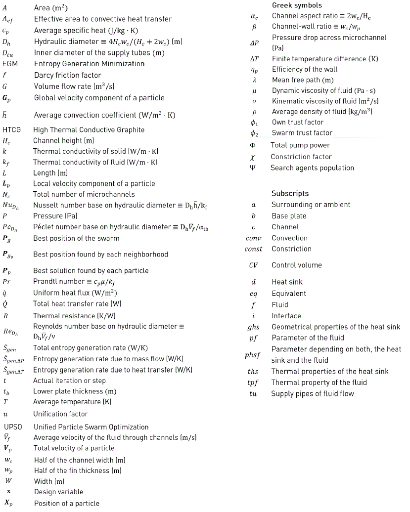
1. Nomenclature
2. Introduction
There are plenty of literature reports regarding simulation and experimental results of different approaches for the optimal design of heat sinks used for a suitable thermal management of electronic components. Through them, designers must select the material for making the required heat sink, the type of coolant, the operating conditions that best match the requirements, and the overall cost of the implementation, principally. Each of the above mentioned options has several alternatives, e.g. the shape of the heat sink, the physicochemical characteristics of the heat sink surface, the physicochemical properties of the working fluid and its flow regime, the convective heat transfer coefficient, and so on. For the present study, it was of interest to find a commercially available material with high thermal conductivity for building microchannel heat sinks. Alas, an extensive literature review revealed few materials with these characteristics. There is now, for example, accessible Oxygen Free High thermal Conductivity copper (OFHC) (k=400 W/m∙K). As stated in [1], the thermal conductivity of crystalline graphite could reach values of the order of 3000 W/m∙K. More recently, synthetically made high thermal conductive graphite (HTCG) was developed from a highly oriented graphite polymer film [2]. It has thermal conductivities of the order of 1300-1900 W/m∙K. Furthermore, it can be composited with conventional polymers, in order to get microchannel heat sinks with different shapes and required thermal conductivities and densities, more easily. In [3] is reported an investigation related to the measurement of the thermal conductivity of graphene suspended across channels in a Si/SiO2 wafer. They claimed extremely high thermal conductivity, in the range of 3080–5150 W/m∙K, for this material. In [4], it was prepared composite phase change materials (PCM) using exfoliated graphite nanoplateles (xGnP), paraffin/xGnP with high electric and thermal conductivity. The thermal conductivity of the composite increased with the xGnP loading. [5] describes the preparation of a high thermal conductive thin graphite film with a thickness about 2.1 µm using a thin polymer film as a start material. The a-b plane thermal diffusivity of the film was measured. They obtained a graphite film composed of highly oriented graphite layers in a-b plane. Similarly, [6] describes the fabrication of graphite flake reinforced copper composites. The composite materials prepared with 40 vol.% graphite flakes showed a strong anisotropy in thermal conductivity and values, as high as, 528 W/m∙K at room temperature. Lately, [7] studies the thermal conductivity of shape-stabilized phase-change materials (PCM) for thermal energy storage, based on a soft Fischer–Tropsch paraffin wax blended with ethylene vinyl acetate (EVA). In the same direction, [8] prepared composites made of expanded graphite (EG) and eutectic water solutions of NaNO3-LiNO3, in order to increase the thermal conductivity of high-temperature phase change materials, or PCMs. As he states, a higher graphite percentage (10-30%) progressively increases the thermal conductivity of the composite, with intensifications up to 10. Finally, [9] studied the heat transfer properties of a PCM made of squama expanded graphite (EG) and paraffin. Because of its composition, this kind of material has a high anisotropic thermal conductivity. Their results show that the anisotropic property of the thermal conductivity of the composite PCM is obvious, and the temperature curves are deflexed and scattered during the apparent heat transfer process of the PCMs of liquid state.
It is also known from previous works, that rectangular microchannels provide the best thermal performance with lower thermal resistance [10, 11]. In fact, several researchers report simulation data using this type of microchannels, but with different working fluids, such as water, air, nitrogen, and argon, among several others. Particularly, in [10] it was reported the potential improvement in the overall performance of a rectangular microchannel heat sink using ammonia gas as a coolant. From the simulation point of view, as was mentioned earlier in [12], literature reports several strategies for modeling this type of heat transfer problem, such as the thermal resistance model, fin model, two fin-fluid coupled models, and porous medium model, principally. Several researches have recently started to explore different alternatives not only to construct and to solve the mathematical model, but also to design an optimal heat sink that maximizes the heat transfer process. From all the analytical resources available for designing purposes, the Entropy Generation Minimization (EGM) criterion is the highest disseminated and illustrated in the literature. It is because of its sound thermodynamics basis. The EGM can be applied to each component of a thermodynamic system and it takes into account the irreversibility due to fluid flow, e.g. pressure drop, and the irreversibility due to heat transfer, e.g. heat transfer between finite temperature differences. Hence, it is possible to build an objective function that represents the sum of all components, so appropriate design parameters can be found that guarantee the maximum efficiency of the whole system. The present article summarizes results from several simulation scenarios for designing, based on the EGM criterion, an optimal rectangular microchannel heat sink made of high thermal conductive graphite. Its behavior was compared against a heat sink made of aluminum. Likewise, two working fluids in gas phase were studied: dry air and ammonia gas. In addition, some simulations using water and a nanofluid composed of titanium dioxide nanoparticles and water were done for comparison purposes. This paper begins by briefly describing the mathematical model and the optimization strategy used in the current work, followed by a summary of the methodology, and a discussion of the results. Finally, the main conclusions are laid out.
3. Mathematical model
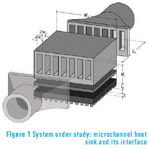
The general deduction of the mathematical model of a similar system was previously presented in some detail in [12]. Subsequently, its most remarkable aspect is described. Figure 1 shows an overview of the model system, including a layer of thermal paste between the heat sink and the chip. The former, is made up of Nc channels with the following specifications: width 2wc, height Hc, length Ld, separated by walls (fins) with a thickness 2wp. The total dimensions of the heat sink are Wd×Ld×Hc, and it is limited by two parallel plates at the top and bottom faces of the fin array. The lower plate has a thickness tb and an area Wd×Ld.
3.1. Total entropy generation rate
In order to model the system (Figure 1) in terms of entropy generation, a representative control volume must be analyzed in terms of mass, energy and entropy balances [13]. Because of symmetry, the control volume (CV) is defined as half a channel of the heat sink, with dimensions (wc+wp )×(Hc+tb+ti )×Ld, with a uniform heat flux  that enters through the bottom plate. Hence, entropy generation rate is given by (1), where the finite temperature difference between the boundary temperature (Ti), and the surrounding temperature (Ta), is ΔT (=Ti-Ta ). Heat transfer rate
  , volume flow rate (GCV) and pressure drop (ΔP) are also included in this equation. After finding
  in (1), the total entropy generation rate
  is found by symmetry [14].

The model given in (2), is defined in terms of the entropy generated due to the irreversibility of heat transfer  and mass flow
  , both of them present during the operation of the whole system. In (2), factor
  relates to the equivalent thermal resistance of the whole heat sink, while factor
  relates to the net power dissipated by the chip; Gd represents the net fluid flow, and Nc (=(Wd/2-wp)/(wc+wp) ) is the number of microchannels in the heat sink.

Additionally,  can be expressed in terms of the wasted available work (or destroyed exergy) as shown in (3), where Φ (=GdΔP) is the total pump power required to maintain the fluid flow. The expressions for calculating Req and ΔP, based on the previously shown operating conditions, are discussed next.

3.2. A simplified equivalent thermal resistance model
For the present case, the equivalent thermal resistance of the heat sink (Req) can be modeled through an analogy to electric circuits, where the heat flux ( ) relates to the electrical current and the finite temperature difference corresponds to the potential difference. Hence, in order to find Req the resistive components related to material changes and heat transfer must be known. This is shown in (4), where Rconst, Rconv and Rf are the resistances due to conduction through the microchannel body, convection on the channels, and calorific capacity of the working fluid, respectively.

The spreading thermal resistance is not considered in this model, i.e., the area available for heat transfer between the base of the heat sink and the chip are assumed to be equal. We have also neglected the other thermal resistances, such as that due to the thermal paste, for example, in order to simplify the analysis. The average temperatures given in (4) relate to those of the base surface (Tb), of the surface contacting the fluid (Ts), and of the fluid outlet (Tf) and inlet (Ta). The constriction thermal resistance, Rconst, due to heat transfer through the microchannel body is given by (5). Now, using Newton's cooling law, an expression for Rconv is given by (6).


This agrees to the expression found by [13], where  is the average convection coefficient and ηp is the thermal efficiency of the fin. Coefficient
  relates to Nusselt number (NuDh)), to the thermal conductivity of the fluid kf, and to the effective hydraulic diameter of the channel Dh (=4wc Hc/(2wc+Hc)). The efficiency ηp, is evaluated through (7), where m is the fin parameter that depends on the geometry of the fin, and on coefficients
  and k. The latter is the thermal conductivity of the heat sink. Finally, the resistance of the working fluid can be found through an energy balance at the fluid flow, yielding (8).


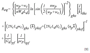
Summarizing, the equivalent thermal resistance of the whole heat sink, defined in (4), is rewritten in (9) as,
3.3. Total pressure drop
This term, found in (2), can be determined with (10), where a relation is made between pressure drop due to load loss and to channel inlet and outlet, as a function of the average density of the fluid (ρ), of the average velocity of the fluid  , of the Darcy friction factor (f), of the length or depth of the channel (Ld), of the hydraulic diameter (Dh), and of the relation given by β (=wc/wp), respectively [13].

In order to calculate the friction factor (f), shown in (10), the correlations given in [14] for smooth surfaces were employed. Equally, for calculating the Nusselt number, the expressions given by [15] when using gas as a working fluid, were used.
3.4. The objective function
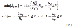
Now, the objective function can be constructed. It compiles all of the above empirical expressions, (4)-(10), in the entropy balance, resulting in (11). To include in this optimization process the pressure drop throughout the supply pipes, several correlations were used, but they are not shown here.
4. Optimization procedure
In order to solve the problem described in (11), many optimization techniques can be selected. A very specific method, based on swarm intelligence and widely used in several engineering applications, is Unified Particle Swarm Optimization (UPSO). UPSO was proposed by Parsopoulos and Vrahatis and it was inspired by the natural process of food search carried out by bird flocks and fish shoals. Basic equations of UPSO are shown in (12) and (13). They consider the swarm's kinematic and the movement and positioning of each individual agent of the swarm.


In equations (12) and (13),  and
and  are the total velocity and the position, respectively, at time step t, for a particle p in the swarm, where p=1,…, Ψ, and Ψ is the total number of agents. χ is the constriction factor; φ1 and φ2 are respectively the self and swarm confidence constants; randi is an uniformly distributed random number between zero and one, where i=1,2,3 and 4;
  ,
,  and
and  are the best positions found by each particle, by each neighbourhood and by the swarm, respectively.
For a defined optimization problem, fobj(X), UPSO pseudocode is briefly described below, using the previously mentioned equations.
- Define χ,φ1,φ2,Ψ and the selection criteria of the neighbourhoods, the search domain Xmin≤Xp≤Xmax, and the objective function fobj(X).
- Randomly assign the initial position of each particle,
 , over the search domain and assign an initial value for the velocity
  .
.
- Evaluate each position, Xp, in fobj and find
 ,
, and
and  .
.
- Use (12) and (13) to calculate
 and
and  , respectively.
- Evaluate each new position in the objective function and update
 ,
, and
and 
- Check stop criteria. If it complies, stop and print results. Otherwise, make t=t+1 and go to step four.
5. Simulation methodology
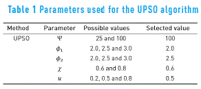
Throughout this work, simulation results were obtained using a computer with the following specifications: ASUS® S46C, CPU Intel® Core™ i7-3537U @ 2.00 GHz – 2.50 GHz, 6 GB RAM, Microsoft® Windows™ 8.1 Single - 64 bits. The parameters assumed for the simulations are declared in Table 1 and the description of each one was given in the previous section. These values were found through a previous study with standard test functions that is not shown here due to space restrictions. Additionally, the data was calculated for 100 runs of each simulation. The optimization algorithm used in this work, i.e. UPSO, including the pseudocode, are fully described elsewhere [12, 16].
5.1. Parameter variation
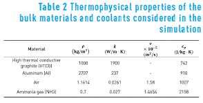
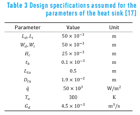
Initially, a set of simulations was conducted to show just the effect of the entropy generation due to the mass flow  , i.e. assuming zero thermal resistance. This limiting case indicates the effect of the flow mass passing through the microchannel heat sink. Also, it shows the importance of the fluid and solid-fluid interphase properties. After that, another group of simulations was ran, but including this time just the thermal resistances due to the convective heat transfer mechanism and the thermal resistance, due to the fluid used as a coolant, (without including the mass flow entropy effect). Next, simulations including the denominated constriction resistance were executed. In order to compare all those effects, air and ammonia gas as coolants and rectangular microchannels made of HTCG and aluminum were used. Table 2 shows the thermophysical properties of the bulk materials and coolants used. The following design parameters were varied through the simulation: heat sink length Ld, between 0.01 m and 1 m; channel width 2wc, between 100 µm and 1000 µm; and volume flow rate Gd, between 0.001 m3/s and 0.01 m3/s. The values shown in Table 3 were used to this end. A completely developed laminar regime was assumed.
6. Results and discussion
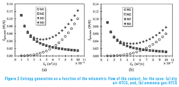
Nomenclature used throughout this section is now presented. M1: represents the optimal simulation results when the entropy generation of the microchannel made of HTCG is due to the mass flow of the coolant only; M2: represents the optimal simulation results when the entropy generation of the microchannel made of HTCG is due to the heat transfer but including Rconv and Rf only; M3: represents the optimal simulation results when the entropy generation of the microchannel made of HTCG is due to the heat transfer but including Rconst, Rconv and Rf only; M4: represents the optimal simulation results when the entropy generation of the microchannel made of HTCG is due to the two contributions, i.e., the thermal and the mass flow effects. Rconst, Rconv and Rf are included. Figure 2a compiles the simulation results for the case dry air-HTCG. As can be observed, each of the limiting cases complies with the expected results. Increasing Gd, the entropy generation due to the mass flow of the coolant increases continuously. On the other hand, due to the high thermal conductivity of the graphite, its effect on the total thermal resistance is negligible and imperceptible at the scale shown. Nevertheless, increasing the mass flow of the working fluid the thermal resistance Rf decreases while keeping constant the other two. The total entropy generation has a minimum value too. When using ammonia gas as the working fluid and keeping the same microchannel made of HTCG, as shown in Figure 2b, the simulation results changed indicating the importance of the physicochemical properties of the working fluid and their effects on the average convective heat transfer coefficient. Nonetheless, previously discussed trends are preserved.
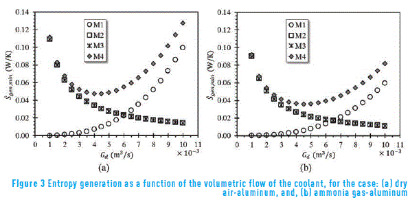
Now, changing to aluminum, i.e. the material which is made of the rectangular microchannel, and keeping dry air as the coolant, the simulation results are quite similar to those shown in Figure 2, as observed in Figure 3a. Figure 3b depicts the behavior of the same system, but now using ammonia gas as the coolant for the same aluminum rectangular microchannel. As before, the same trends are observed. It was also evident that the entropy generation was consistently lower than the shown in Figure 4a. From the simulation point of view, it seems plausible to think that the overall phenomena controlling the heat transfer process, for the present case, is now changing to the side of the fluid instead to the material which the microchannel is made of. The thermal conductivity of the HTCG used in the simulations was of the order of 1900W/m∙K. Using, for example, materials with higher thermal conductivity such as graphene flakes (3080–5150 W/m∙K) would render Rconst to practically zero, but the total thermal resistance will still be dependent on Rconv and Rf. After several simulations, it was observed the relative importance of the three thermal resistances considered here on the overall heat transfer process.
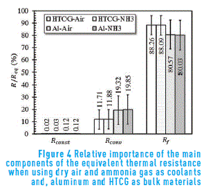
For all cases, the constriction thermal resistance represented less than 0.15% of the total equivalent thermal resistance, as depicted in Figure 4.
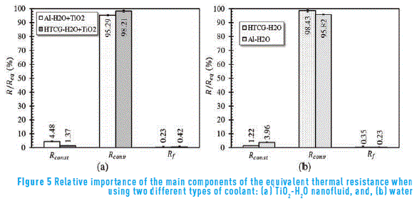
In the same way, the high impact of Rf on the total thermal resistance and consequently on the heat transfer process can be noticed. This is due, including the basic assumptions made for the mathematical modeling construction, to the low density and low heat capacity of the working fluids. In order to have more illustrative examples of this behavior, some additional systems using the same rectangular microchannel were simulated, but changing the coolant to a nanofluid composed of titanium dioxide nanoparticles (9.0 wt/wt%) in water. The correlations and bulk properties required are not shown here, but they can be consulted in [18]. As can be noted from Figure 5, the impact of Rf on the total thermal resistance was drastically diminished, due to the relative high density and high heat capacity of the nanofluid, principally. Now the controlling factor in this case, is the convective resistance.
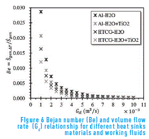
The modest increment of Rconst is also evident. Rconv depends directly on the physical properties of the coolant, microchannel and the convective heat transfer coefficient, so there are a subtle balance of properties, which makes optimal the design and performance of a microchannel. The coupling of such properties makes the optimal design, without including the costs, a rather interesting real life problem. In a deeper analysis about the entropy generation for the system described above, Figure 6 shows the variation of Bejan number (Be) with the flow rate of the two working fluids, that is, TiO2-water nanofluid, and water, for two different microchannels. As can be perceived, there is a sharp decrease of Bejan number when Gd increases. As soon as the volume flow rate of the working fluid reaches values above 0.007 m3/s, Be becomes practically zero. It could be interpreted as the continuous and dominant effect of the entropy generation due to the fluid friction on the heat transfer process.
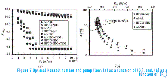
On the other hand, the Nusselt number of the process was analyzed. It behaves as shown in Figure 7a. It seems that at higher flow rates of the working fluid, i.e. higher Gd, conduction is the dominant mechanism for heat transfer, or equivalently, the film coefficient seems to decrease with the length. This is more notorious when the material was a high thermal conductive graphite and air was the working fluid. Nevertheless, the changes were rather small. However, when the continuous phase is water the situation is different. Globally the Nusselt number is perceptibly lower, when the coolant is a nanofluid and the material for the making of the microchannel is a HTCG. It seems likely due to the dependence of the micro-flow hydrodynamics and the heat transfer process on the solid-liquid interfacial interactions, at such reduced length scales. Besides, it is currently known that the convective heat transfer coefficient is a function of the local velocity profile and could vary appreciably along the walls of the microchannel. Figure 7b shows the relation between pump power (Φ) and the equivalent thermal resistance (Req). Furthermore, it illustrates the relationship between the irreversibilities due to mass and heat transfer. The black arrow in this figure, represents the optimal design with the lowest value of  for all the simulation scenarios analyzed.
It appears to be that a small change in the total or effective thermal resistance has a profound effect on the energy per unit time required to move the working fluid through the microchannel. Or in other words, any variation on the thermal resistant will alter the performance of the microchannel. The arrow represents minimum entropy generation rate at a specific volume flow rate Gd.
CIOs (Chief Information Officers) are becoming CPOs (Chief Process Officers); therefore, a solution that allows companies to radically address their multiple business needs through the management and improvement of their processes, along with room for rethinking, rebuilding and boosting the performance of their processes around a wide range of models, is necessary. We expect that our proposal –along with others– offers organizations the appropriate readiness to face the challenges presented by the niche markets around the world.
7. Conclusions
This article showed some of the most important results dealing with the use of one of the best material (a Higher Thermal Conductive Graphite) for making a heat sink, and its relative effect on the global heat transfer process. As can be initially concluded, it seems that the problem of heat transfer management on electronic components, using heat sinks with very high thermal conductivity (such as HTCG) and a gas as working fluid, comes from the side of the fluid. The thermal resistance and other surface properties imposed by the solid-fluid interphase appears to be the controlling mechanism for the overall heat dissipation, as well as, by the physicochemical properties of the coolant (density, heat capacity, viscosity, thermal conductivity and the eventual presence of another phases or components, principally). As it is evident, the next step is to find the kind of fluid or fluids that could markedly decrease the total thermal resistance. Simulations results showed that a nanofluid composed of titanium dioxide and water, in conjunction with a high thermal conductive graphite is an acceptable combination to obtain a good performance microchannel.
8. Acknowledgements
The authors would like to express their gratitude to Vicerrectoría de Investigación y Extensión, at Universidad Industrial de Santander (Colombia), for the support granted through project 1807.
9. References
1. H. Fukushima, L. Drzal, B. Rook and M. Rich, ''Thermal conductivity of exfoliated graphite nanocomposites'', J. Therm. Anal. Calorim., vol. 85, no. 1, pp. 235-238, 2006. [ Links ]
2. Hunan Chen Xiang Carbon Co., Ltd. (CX-CARBON), Products, 2014. [Online]. Available: http://www.cx-carbon.com/product/. Accessed on: Apr. 4, 2015. [ Links ]
3. S. Ghosh et al., ''Extremely high thermal conductivity of graphene: Prospects for thermal management applications in nanoelectronic circuits'', Appl. Phys. Lett., vol. 92, no. 15, pp. 15-17, 2008. [ Links ]
4. S. Kim and L. Drzal, ''High latent heat storage and high thermal conductive phase change materials using exfoliated graphite nanoplatelets'', Sol. Energy Mater. Sol. Cells, vol. 93, no. 1, pp. 136-142, 2009. [ Links ]
5. A. Tatami, M. Tachibana, T. Yagi, M. Akoshima and M. Murakami, ''High Thermal Conductive Graphite Films from Thin Polymer Films'', in 15th International Heat Transfer Conference, Kyoto, Japan, 2014, p. 7. [ Links ]
6. C. Zhang, X. He, Q. Liu, S. Ren and X. Qu, ''Fabrication and thermo-physical properties of graphite flake/copper composites'', J. Compos. Mater., pp. 1-8, 2014. [ Links ]
7. M. Mochane and A. Luyt, ''The effect of expanded graphite on the thermal stability, latent heat, and flammability properties of EVA/wax phase change blends'', Polym. Eng. Sci., vol. 55, no. 6, pp. 1255-1262, 2015. [ Links ]
8. Y. Li, ''Research on Expanded Graphite/Nitrate High-Temperature Composite Phase Change Materials'', Appl. Mech. Mater., vol. 740, pp. 11-14, 2015. [ Links ]
9. J. Luo et al., ''Numerical and experimental study on the heat transfer properties of the composite paraffin/expanded graphite phase change material'', Int. J. Heat and Mass Transf., vol. 84, pp. 237-244, 2015. [ Links ]
10. A. Adham, N. Mohd and R. Ahmad, ''Optimization of an ammonia-cooled rectangular microchannel heat sink using multi-objective non-dominated sorting genetic algorithm (NSGA2)'', Heat and Mass Transf., vol. 48, no. 10, pp. 1723-1733, 2012. [ Links ]
11. A. Adham, N. Mohd and R. Ahmad, ''Thermal and hydrodynamic analysis of microchannel heat sinks: A review'', Renew. Sustain. Energy Rev., vol. 21, pp. 614-622, 2013. [ Links ]
12. J. Cruz, I. Amaya and R. Correa, ''Optimal rectangular microchannel design, using simulated annealing, unified particle swarm and spiral algorithms, in the presence of spreading resistance'', Appl. Therm. Eng., vol. 84, pp. 126-137, 2015. [ Links ]
13. W. Khan, M. Yovanovich and J. Culham, ''Optimization of microchannel heat sinks using entropy generation minimization method'', in 22nd Annual IEEE Semiconductor Thermal Measurement and Management Symposium, Dallas, USA, 2006, pp. 78-86. [ Links ]
14. F. Incropera and D. DeWitt, Fundamentals of heat and mass transfer, 4th ed. New York, USA: John Wiley & Sons, 1996. [ Links ]
15. S. Kim and D. Kim, ''Forced Convection in Microstructures for Electronic Equipment Cooling'', J. Heat Transfer, vol. 121, no. 3, p. 639-645, 1999. [ Links ]
16. K. Parsopoulos and M. Vrahatis, ''Unified Particle Swarm Optimization for Solving Constrained Engineering Optimization Problems'', in 1st International Conference on Advances in Natural Computation (ICNC), Changsha, China, 2005, pp. 582-591. [ Links ]
17. M. Kleiner, S. Kühn and K. Haberger, ''High performance forced air cooling scheme employing microchannel heat exchangers'', IEEE Trans. on Components, Packaging and Manuf. Technol., A, vol. 18, no. 4, pp. 795-804, 1995. [ Links ]
18. N. Hajialigol, A. Fattahi, M. Ahmadi, M. Qomi and E. Kakoli, ''MHD mixed convection and entropy generation in a 3-D microchannel using Al2O3–water nanofluid'', J. Taiwan Inst. Chem. Eng., vol. 46, pp. 30-42, 2015. [ Links ]


