Services on Demand
Journal
Article
Indicators
-
 Cited by SciELO
 -
 Access statistics
Related links
-
 Cited by Google
 -
 Similars in
SciELO
 -
 Similars in Google
Share
Revista Facultad de Ingeniería Universidad de Antioquia
Print version ISSN 0120-6230
Rev.fac.ing.univ. Antioquia no.78 Medellín Mar. 2016
https://doi.org/10.17533/udea.redin.n78a15
DOI: 10.17533/udea.redin.n78a15
ARTÍCULO ORIGINAL
Experimental study of water infiltration on an unsaturated soil-geosynthetic system
Estudio experimental de infiltración de agua en un sistema suelo-geosintético parcialmente saturado
Edwin Fabián García-Aristizábal*, Carlos Alberto Vega-Posada, Alba Nury Gallego-Hernández
Escuela Ambiental, Facultad de Ingeniería, Universidad de Antioquia UdeA. Calle 70 # 52-21. A. A. 1226. Medellín, Colombia.
* Corresponding author: Edwin Fabián García Aristizábal, e–mail: edwin.garcia@udea.edu.co
ISSN 0120–6230
e–ISSN 2422–2844
(Received April 13, 2015; accepted August 4, 2015)
ABSTRACT
This investigation presents experimental results from soil-geosynthetic column tests constructed to study the drainage capability of geosynthetics installed within an unsaturated soil and subjected to a water infiltration process. Two different types of permeable geosynthetics were tested; namely, non-woven geotextile and woven non-woven geocomposite. The infiltration process was monitored using negative/positive pore water pressure and volumetric water content transducers placed above and below the geosynthetic. The results showed that the geosynthetics behaved as an impermeable layer until the surrounding soil was nearly saturated. The geosynthetics started draining water laterally only when the pore water pressure within the soil above it was positive or negative but close to zero. This study intends to provide some insights into the physics of soil-geosynthetics performance, and to complement the available technical data used to conduct numerical simulations of complex soil-structures subjected to water infiltration processes.
Keywords: Infiltration, soil-geosynthetic, column-test, unsaturated soil, experimental study
RESUMEN
Esta investigación presenta resultados experimentales de columnas de suelo-geosintético construidas para estudiar la capacidad de drenaje de geosintéticos instalados en suelos parcialmente saturados y sometidos a procesos de infiltración de agua. Se ensayaron dos tipos diferentes de geosintéticos permeables denominados geotextil no tejido y geocompuesto tejido-no tejido. El proceso de infiltración se monitoreó usando sensores de presión de poros negativa/positiva y de contenido volumétrico de agua, los cuales se colocaron por encima y por debajo del geosintético. Los resultados mostraron que los geosintéticos se comportaron como una capa impermeable hasta que el suelo circundante estaba casi saturado. Los geosintéticos empezaron a drenar agua lateralmente solo cuando la presión de poros en el suelo arriba de él era positiva o negativa pero cercana a cero. Este estudio busca proveer algunas ideas sobre la física del funcionamiento de suelo con geotextil y complementar la información técnica existente usada para realizar simulaciones numéricas de estructuras de suelo complejas sometidas a procesos de infiltración.
Palabras clave: Infiltración, suelo-geosintético, ensayo de columna, suelo parcialmente saturado, estudio experimental
1. Introduction
Geosynthetics have been extensively studied as a soil reinforcement material [1-5]. Generally, these studies have focused on determining the increase in shear strength of the reinforced soil-structure. Other investigations have focused their efforts on the behavior of geosynthetics as draining materials; however, in some cases these studies provide contradictory results. For instance, several authors have reported a satisfactory performance and effectiveness of the geosynthetics as a drainage layer [6-10]. Meanwhile, others have found that the geosynthetics do not always behave as a drainage material [11-15]. In some cases, it had been reported that geosynthetics may retard water flow in situations where the pore water pressure is negative [16, 17], leading to local failures as shown experimentally by [13].
Some studies have been conducted to understand the one-dimensional infiltration process in soil-geotextile layers. For instance, [18] performed a numerical analysis to model the infiltration process into a sand-geotextile column and compared the results with experimental data from [19]. [20] presented experimental results of two 1-D capillary barrier models using gravelly sand and geosynthetic as coarse-grained layers. [21] described a 1-D column apparatus that was constructed to study the response of sand-geotextile layers subjected to a constant head water infiltration process; additionally, they were the first to report the response of a woven geotextile embedded in sand under 1-D infiltration conditions. Later, [22] presented laboratory results of 1-D sand-geotextile columns subjected to water infiltration, to quantify the geotextile water characteristic curves for a woven and a nonwoven geotextile. Finally, [23] reported the results of numerical analysis carried out to reproduce experimental results previously obtained for sand-geotextile layers. In spite of all the valuable works, the effect of the hydraulic behavior of these layers is not yet fully understood. Especially, there is still a need for further experimental studies on infiltration processes to understand the hydraulic interaction between soil and geosynthetics.
This paper presents experimental results from two-column tests reinforced with two types of geosynthetics, and subjected to a water infiltration process. The pore-water pressures and water contents were monitored and plotted against time to study the hydraulic response of the soil-geosynthetic layers. The hydraulic interaction between the soil and geosynthetic is examined based on the pore water pressure and water content readings taken above and below the geosynthetics. The results show that the geosynthetic starts to work as a drainage material when the pore water pressure is positive, or negative but close to zero (nearly saturated). Finally, this study intends to provide some insights into the physics of soil-geosynthetics performance, and to complement the available technical data used to conduct numerical simulations of complex soil-structures subjected to water infiltration processes.
2. Test materials and column tests
2.1. Test materials
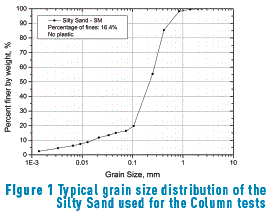
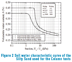
Figures 1 and 2 show a typical grain size distribution curve and the soil water characteristic curve (SWCC) of the sand sample used for the construction of the column tests, respectively. A soil water characteristic curve was measured using Tempe Pressure cell and the experimental data was fitted using Fredlund and Xing Equation [24]. The specific gravity (Gs) was 2.75; the minimum and maximum void ratios (emin and emax) were 1.01 and 1.59, respectively; the dry unit weight  was 17.2 kN/m3, and the optimum water content (wopt) was 16.0%. The soil is classified as a Silty Sand (SM) according to the Unified Soil Classification System [25]. Additionally, two different types of geosynthetics, non-woven geotextile and woven non-woven geocomposite, were tested to determine the moment at which the geotextile began draining water when the system was subjected to a water infiltration process. Table 1 summarizes the physical properties of the geosynthetics.
2.2. Pore water pressure and moisture measurement system
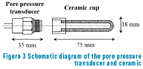
Pore pressure transducers were used to monitor the positive and negative water pressures induced in the soil column during water infiltration. The pore pressure transducer is connected to the saturated porous ceramic. It converts water pressure into electric quantities. When water comes into the ceramic, the diaphragm of the sensor deforms concavely, measuring positive pore water pressure, and when the water comes out of the ceramic, the diaphragm deforms convexly, measuring negative pore water pressures. Four (4) pressure transducers manufactured by KYOWA Electronic Co. Ltd. (Model PGM-05KG), with a 50-kPa capacity and natural frequency of 3 kHz, were distributed along the sand column; two above and two below the geosynthetic. A porous ceramic was attached at the bottom of the transducers to allow the measurement of negative pore water pressures. The porous ceramic had a width of 18 mm, a length of 75 mm, a thickness of 3 mm and an air entry value of 100 kPa. The transducer and attached porous ceramic can measure up to 75 kPa positive and negative water pressures. Figure 3 shows a schematic diagram of the pore pressure transducer.
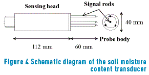
Soil moisture transducers were used to monitor volumetric water content  changes. A simplified standing wave measurement was used to determine the impedance of a sensing rod array, and hence, the volumetric content of the soil matrix. Two soil moisture content transducers were used in the column test (TDR ThetaProbe and ML2x). The ThetaProbe consists of an input/output cable, probe body and a sensing head. The cable provides connection for a suitable power supply and for an analogue signal output. The probe body contains an oscillator, a specially designed internal transmission line and measuring circuitry within a waterproof housing. The sensing head has an array of four rods, the outer three if which, connected to instrument ground, form an electrical shield around the central, signal rod. This behaves as an additional section of transmission line having an impedance that depends on the dielectric constant of the matrix into which it is inserted [26]. Figure 4 shows a schematic diagram of this transducer. They were calibrated using a cylinder with a constant volume and filling it with soil at different water contents. At each water content, the sensor was placed inside the cylinder and a reading was taken. Then, a representative sample of soil was taken to the oven and the volumetric water content determined was correlated to the reading of the signal rod.
2.3. Data acquisition system
The output signals from the electronics transducers were sent to an A/D (analog-to-digital) converter and finally to the computer, where data sampling was recorded at the required frequency. The A/D converter is a device that converts the instantaneous voltage that it receives as output, from the pore water pressure and volumetric water content transducers, into a digital format to be fed to the computer port for subsequent data storing and processing.
2.4. Column Test preparation
Two plastic boxes were used for the preparation of the column test. They were 42 cm in length, 32 cm in width, and 30 cm in height. The column test constructed was 50 cm in height. The silty sand soil was mixed with water to achieve an initial water content between 0.15 and 0.20 m3/m3 (Saturation between 30% and 40%), and a dry unit weight of 13.5 kN/m3. Next, the moist soil was placed in a series of horizontal layers with a final thickness of 5 cm. The surface of each layer was scarified prior to placement of the new one. This procedure was repeated until the total height of the soil column was reached.
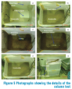
The geosynthetic was placed once the soil column reached a height of 30 cm; first box of the column test as shown in Figure 5. A pore water pressure sensor and a volumetric water content sensor were installed at a height of 10 cm and 50 cm, as well as immediately below and above the geosynthetic. Before placing the pore water pressure sensors, the soil was scarified to ensure a good contact between the soil and ceramic cup. The procedure for placing the moisture content sensors consisted of removing a portion of the soil next to the pore water pressure sensors to insert it laterally into the compacted soil. After placement of the sensors, the height of the soil column was completed by tamping the soil, as explained before.
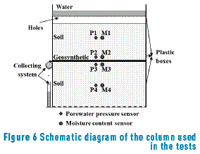
The inner walls of the column were covered from the bottom to the top with a vinyl sheet to avoid water leakage during the test. Once the geosynthetic was placed, a second vinyl sheet was taped to the geosynthetic and extended to the top of the column to prevent water infiltration along the perimeter, and to ensure that all the infiltrated water seeps through the geosynthetic. Figures 5(a-f) show the steps followed to construct the soil column and to install the transducers. Figure 6 shows a schematic diagram of the column once constructed, and the location of the geosynthetic and transducers.
After constructing the soil column, water was applied at the top by using a plastic box perforated at the bottom. Ten (10) liters of water, distributed uniformly over the top, were constantly applied for approximately 10 minutes. The water drained horizontally by the geosynthetic was collected with a lateral pipe (see Figures 5 and 6), and the time at which the geosynthetic started and stopped draining water was recorded.
3. Experimental results and discussion
Two (2) soil columns were tested, one with a non-woven geotextile and another with a woven-non woven geocomposite, to analyze the drainage behavior of the geosynthetics within the soil. The experiment consisted of initially adding 10 liters of water at the top of the soil column, and 10 more liters after two hours. At each stage, the water was maintained for approximately 10 minutes. During the infiltration process, the time at which the geosynthetic started and stopped draining water laterally was recorded to determine the moment when the geosynthetic worked as a drainage material. Additionally, the recorded time was also correlated with the volumetric water contents and pore water pressures measured during testing.
3.1. Time histories of the infiltration process
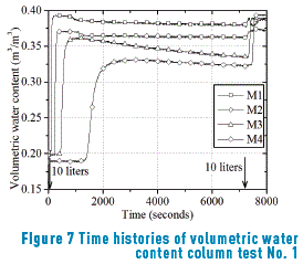
Figure 7 shows the volumetric water content responses of the column test with the non-woven geotextile. From this figure, it can be observed that the initial water content within the column is close to 0.20 m3/m3. When the 10-liters of water was applied at the top (at time t = 0 s), the volumetric water content  increased along the entire column, showing a faster response the sensor located closer to the top of the column. During the water infiltration process, the volumetric water content of the soil above the geotextile remained greater than the one below it, suggesting that water was accumulating above the geotextile (sensors M1 and M2). During the first two (2) hours, the volumetric water content decreased slowly, especially for the soil located right below the geotextile (M3). At this time, geotextile prevents water to pass through it; consequently, water within the soil below the geotextile continues draining down due to gravity, which makes the water content to decrease, as shown by sensor M3. Finally, when the second amount of water was applied, at time t= 7200 s, the volumetric water content in the column increased again, reaching values between 0.35 and 0.40 m3/m3.
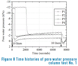
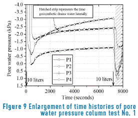
The infiltration process can also be explained by the pore water pressure responses shown in Figures 8 and 9. Figure 9 is an enlargement of Figure 8 for a range of pore water pressures between -4.0 kPa and 1.5 kPa. From these figures, it can be observed that when the first 10 litters of water were applied at t=0 s, water began to infiltrate the geotextile, and a few seconds later, the transducers reported an increase of pressure (reduction of suction). The pore water pressure measured right above the geotextile was larger (Sensor P2) than the one measured right below it (Sensor P3), with a pressure difference of about -1.5 kPa, after 7200 seconds. During this period of time, water did not drain horizontally along the geotextile. However, when the second 10 litters of water were applied, the pore water pressure suddenly increased to positive values and the geotextile started to drain water laterally, and continued until the pressure within the soil above the geotextile reached a value around -0.47 kPa. The results showed that the geosynthetic started to work as a drainage material when the pore water pressure was positive, or negative but close to zero (nearly saturated). These results are consistent with those presented by [13, 17, 18].
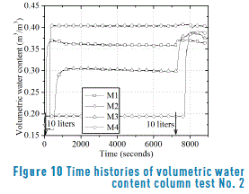
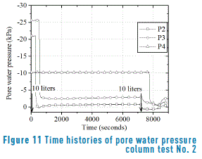
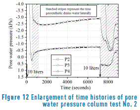
Similar results were obtained for the soil column with a woven non-woven geocomposite. Figure 10 presents the volumetric water content response during the infiltration process, and Figures 11 and 12 the pore water pressure time history responses. In Figures 11 and 12, the readings from sensor P1 were omitted because it did not respond during the experiment. It can be observed in Figure 12 that water started to accumulate above the geocomposite, and positive excess pore water pressures began to build up after 500 s approximately; at that instant, the geocomposite started to drain out water horizontally. Water drainage stopped when the value of pore water pressure above the geocomposite was negative, around -0.40 kPa. The pore water pressure within the soil above the geocomposite decreased slowly, but it remained larger than the pore water pressure above the geotextile in the column test 1 (See Figure 9). This response is expected since the geocomposite is less permeable than the geotextile, and it is more difficult for the infiltrated water to pass through it. After applying the second 10 litters of water, the pore water pressure suddenly increased and the geocomposite started to drain water out and stopped when the suction within the soil above the geocomposite reached a value around -0.37 kPa. Similarly to the results obtained in column test 1, the geocomposite allowed the lateral drainage of water when the pore water pressure in the soil above it was positive, or negative but close to zero.
3.2. Drainage capability of the permeable geosyntheticss
In Figures 9 and 12, the vertical hatched stripes show the period of time when the geosynthetics drained water laterally from the column. Geosynthetics started draining water when the pore water pressure above them was positive, around 0.7 kPa for the geotextile and 0.5 kPa for the geocomposite, and even when the pressure dropped to negative values. Geosynthetics suddenly stopped draining when the pressure reached a value of -0.47 kPa for the geotextile and -0.37 kPa for the geocomposite. It is concluded, by analyzing the results from the two column tests that the geosynthetics behaved as a drainage material when the pore water pressures above them were positive or negative, but close to zero.
For unsaturated permeable geosynthetics, permeability is a function of the suction acting on it; the greater the suction, the lower the permeability. Then, in these cases, geosynthetics start draining water laterally when suction approach to zero, which means that permeability is increasing. However, in this research, the permeability of the soil and geosynthetics were not measured.
3.3. Capillary barrier
As explained by [27], "a capillary barrier develops when an unsaturated fine-grained soil layer is underlain by another unsaturated porous material with relatively large-sized pores, such as a coarse-grained soil layer (e.g. sand, gravel), or a porous geosynthetic (e.g. a nonwoven geotextile)". In the case of permeable geosynthetics subjected to water infiltration, the mechanism of the capillary barrier makes the infiltrated water to accumulate within the fine-grained soil immediately above the permeable geosynthetics. This is because for geosynthetics, the permeability decreases rapidly when suction increases or saturation reduces, making their permeability smaller than that of fine-grain soils. This prevents water to move vertically through the soil-geosynthetic systems. Therefore, the capillary barrier ceases when geosynthetics are saturated or near saturation, when permeabilities are maximum.
Column tests 1 and 2 showed that the infiltrated water accumulated above the geotextile and geocomposite. The volumetric water contents and pore water pressures recorded immediately above and below the geosynthetics showed that they acted as an impermeable barrier preventing water seepage through them. During the water infiltration process, higher water contents and pore pressures were recorded by sensors (M2 and P2) above the geosynthetic; on the other hand, sensors located below registered a lower volumetric water content and pore water pressure (M3 and P3, respectively). These results imply that the geosynthetics were working as a capillary barrier.
The experimental study of infiltration processes on unsaturated soil-geosynthetic systems allow a better understanding of the behavior and response of many complex engineering problems related to earth-structures, which involve complex mechanical and hydraulic interactions among unsaturated geomaterials. For instance, when mechanical stabilized earth structures reinforced with geosynthetics are subjected to water infiltration, the capillary barrier may have harmful effects due to the accumulation of water above the geosynthetics, causing local or global failure. On the other hand, geosynthetics can be used in pavement structures as a capillary barrier to prevent the capillary flow when the ground water table is rising to the surface, helping to maintain the soil water content and the strength of the layered materials that are part of the pavement structure.
4. Conclusions
An experimental investigation on the infiltration process into two soil-geosynthetic columns was performed to evaluate the drainage performance of two geosynthetic fabrics, namely non-woven geotextile and woven non-woven geocomposite. The drainage performance of the geosynthetics was investigated by measuring pore water pressures and volumetric water contents when two sets of 10 liters of water were added to the columns. The first 10 litters of water were added at the beginning of the tests and the second one two hours after. A discussion about the drainage capability of the geosynthetics and their function as a capillary barrier was presented. The major conclusions derived from these experiments are summarized as follows:
- It is possible to describe the infiltration process and the drainage capability of permeable geosynthetics by measuring the water content or/and the pore water pressures in a soil-geosynthetics layers. The differences between these measurements, above and below the geosynthetics, provide an insight of the effect of geosynthetics on the hydraulic behavior when they are used as a reinforced material.
- A geosynthetic embedded within an unsaturated soil will behave as an impermeable layer until the surrounding soil is nearly saturated. The geosynthetic will not begin draining water laterally until the excess pore water pressure above it is positive, and it will stop draining when the pore pressure is negative but close to zero.
- It is observed that, in both soil-geosynthetic columns, the infiltrated water accumulated above the geosynthetics. The two geosynthetics, non-woven geotextile and woven non-woven geocomposite, worked as a capillary barrier, maintaining the soil above them with a high degree of saturation. This response was recorded by the transducers.
5. References
1. P. Fox and T. Stark, "State-of-the-art report: GCL shear strength and its measurement – ten-year update", Geosynthetics International, vol. 22, no. 1, pp. 3-47, 2015. [ Links ]
2. F. Portelinha, J. Zornberg and V. Pimentel, "Field performance of retaining walls reinforced with woven and nonwoven geotextiles", Geosynthetics International, vol. 21, no. 4, pp. 270-284, 2014. [ Links ]
3. A. Taha, M. Naggar and A. Turan, "Experimental and numerical study on lateral behaviour of geosynthetic-reinforced pile foundation system", Geosynthetics International, vol. 21, no. 6, pp. 352-363, 2014. [ Links ]
4. J. Lovisa, S. Shukla and N. Sivakugan, "Behaviour of prestressed geotextile-reinforced sand bed supporting a loaded circular footing", Geotextiles and Geomembranes, vol. 28, no. 1, pp. 23-32, 2010. [ Links ]
5. S. Tan, S. Chew and W. Wong, "Sand–geotextile interface shear strength by torsional ring shear tests", Geotextiles and Geomembranes, vol. 16, no. 3, pp. 161-174, 1998. [ Links ]
6. L. Lamy, L. Lassabatere, B. Bechet and H. Andrieu, "Effect of a nonwoven geotextile on solute and colloid transport in porous media under both saturated and unsaturated conditions", Geotextiles and Geomembranes, vol. 36, pp. 55-65, 2013. [ Links ]
7. M. Ghazavi and M. Roustaei, "Freeze–thaw performance of clayey soil reinforced with geotextile layer", Cold Regions Science and Technology, vol. 89, pp. 22-29, 2013. [ Links ]
8. B. Chattopadhyay and S. Chakravarty, "Application of jute geotextiles as facilitator in drainage", Geotextiles and Geomembranes, vol. 27, no. 2, pp. 156-161, 2009. [ Links ]
9. S. Tan et al., "Large-scale drainage behavior of composite geotextile and geogrid in residual soil", Geotextiles and Geomembranes, vol. 19, no. 3, pp. 163-176, 2001. [ Links ]
10. J. Zornberg and J. Mitchell, "Reinforced soil structures with poorly draining backfills. Part I: Reinforcement interaction and functions", Geosynthetics International, vol. 1, no. 2, pp. 103-148, 1994. [ Links ]
11. R. Koerner and G. Koerner, "Lessons learned from geotextile filter failures under challenging field conditions", Geotextiles and Geomembranes, vol. 43, no. 3, pp. 272-281, 2015. [ Links ]
12. O. Akay, A. Özer and G. Fox, "Assessment of EPS block geofoam with internal drainage for sandy slopes subjected to seepage flow", Geosynthetics International, vol. 21, no. 6, pp. 364-376, 2014. [ Links ]
13. E. Garcia, C. Chaminda and T. Uchimura, "Function of permeable geosynthetics in unsaturated embankments subjected to rainfall infiltration", Geosynthetics International, vol. 14, no. 2, pp. 89-99, 2007. [ Links ]
14. G. Richardson, "Fundamental mistakes in slope design", Geotechnical Fabrics Report, Mar. 1997. [ Links ]
15. W. Dierickx, "Determination of water penetration resistance of geotextiles", ASTM Special Technical Publication 1281, Jan. 1996. [ Links ]
16. T. Iryo and R. Rowe, "On the Hydraulic behavior of unsaturated nonwoven geotextiles", Geotextiles and Geomembranes, vol. 21, no. 6, pp. 381-404, 2003. [ Links ]
17. T. Iryo and R. Rowe, "Infiltration into an embankment reinforced by nonwoven geotextiles", Canadian Geotechnical Journal, vol. 42, no. 4, pp. 1145-1159, 2005. [ Links ]
18. T. Iryo and R. Rowe, "Numerical study of Infiltration into a soil-geotextile column", Geosynthetics International, vol. 11, no. 5, pp. 377-389, 2004. [ Links ]
19. A. Ho, "Experimental and numerical investigation of infiltration ponding in one-dimensional sand-geotextile columns", MSc thesis, Queen's University, Kingston, Canada, 2000. [ Links ]
20. H. Krisdani, H. Rahardjo and E. Leong, "Experimental Study of 1-D Capillary Barrier Model using Geosynthetic Material as the Coarse-Grained Layer", in 4th International Conference on Unsaturated Soils, Carefree, USA, 2006, pp. 1683-1694. [ Links ]
21. R. Bathurst, A. Ho and G. Siemens, "A column apparatus for investigation of 1-D unsaturated-saturated response of sand-geotextile systems", Geotechnical Testing Journal, vol. 30, no. 6, pp. 433-441, 2007. [ Links ]
22. R. Bathurst, G. Siemens, A. Ho, "Experimental investigation of infiltration ponding in one-dimensional sand-geotextile columns", Geosynthetics International, vol. 16, no. 3, pp. 158-172, 2009. [ Links ]
23. G. Siemens and R. Bathurst, "Numerical parametric investigation of infiltration in one-dimensional sand–geotextile columns", Geotextiles and Geomembranes, vol. 28, no. 5, pp. 460-474, 2010. [ Links ]
24. D. Fredlund and A. Xing, "Equation for the soil-water characteristic curve", Canadian Geotechnical Journal, vol. 31, no. 4, pp. 521-532, 1994. [ Links ]
25. American Society for Testing and Materials (ASTM), Standard Practice for Classification of Soils for Engineering Purposes (Unified Soil Classification System), Standard ASTM D2487, 2011. [ Links ]
26. J. Miller and G. Gaskin, "Theta Probe ML2x. Principles of operation and applications", Macaulay Land Use Research Institute, Tech. Note (2nd ed), 1999. [ Links ]
27. J. Zornberg, A. Boauazza and J. McCartney, "Geosynthetic Capillary Barriers: Current State of Knowledge", Geosynthetics International, vol. 17, no. 5, 2010. pp. 273-300, 2010. [ Links ]


