


Services on Demand
Journal
Article
 English (pdf)
 Article in xml format
 Article references
 Send this article by e-mail
Indicators
-
 Cited by SciELO
 -
 Access statistics
Related links
-
 Cited by Google
 -
 Similars in
SciELO
Similars in
SciELO -
 Similars in Google
Share

 Permalink
Revista Facultad de Ingeniería Universidad de Antioquia
Print version ISSN 0120-6230
Rev.fac.ing.univ. Antioquia no.79 Medellín Apr./June 2016
https://doi.org/10.17533/udea.redin.n79a14
ARTÍCULO ORIGINAL
DOI: 10.17533/udea.redin.n79a14
Horizontal vortex single chamber hydroturbine
Hidroturbina de vórtice horizontal de una cámara
Sergio Antonio Zarate-Orrego, Gerardo Andrés Torres-Casierra, Efraín Baldemar del Risco-Moreno*
Escuela de Ingeniería de los Recursos Naturales y del Medio Ambiente (EIDENAR), Universidad del Valle. Ciudad Universitaria Meléndez, Calle 13 # 100-00. A. A. 25360. Cali, Colombia.
* Corresponding author: Efraín del Risco Moreno, e-mail: efrain.del@correounivalle.edu.co
DOI: 10.17533/udea.redin.n79a14
ISSN 0120-6230
e-ISSN 2422-2844
(Received May 26, 2015; accepted April 04, 2016)
ABSTRACT
A machine with high-form resistance was evaluated in order to extract energy from a creek, river or ocean stream, and generate electricity. Without appropriate instruments, research turned into qualitative. It was assumed that if it still worked, its behavior may improve softening its form. The device has a semi-convergent nozzle with flat walls, a cylindrical Vortex Chamber and a runner. It captures water through its largest section and downloads tangentially by its lower section into the Vortex Chamber. It has a hole in one of its sidewalls. This way, it forms a horizontal vortex that spins a rotor whose shaft drives an electric generator. The experimental work carried out showed that it is possible to generate electricity with this device despite the adverse conditions in which it was tested.
Keywords: Renewable energy, vortex chamber, power, turbine design
RESUMEN
Se evaluó una máquina con alta resistencia de forma para extraer energía de una quebrada, río o corriente marina, y generar electricidad. Sin instrumentos adecuados, la investigación fue cualitativa. Se supuso que si aun así funcionaba, su comportamiento podía mejorar suavizándose la forma. El aparato tiene una tobera semi-convergente de paredes planas, una cámara de vórtice cilíndrica y un rodete. Capta agua por su sección mayor y la descarga tangencialmente por su sección menor en la cámara de vórtice; ésta tiene un orificio en una de sus paredes laterales. Así forma un vórtice horizontal que hace girar un rodete cuyo eje acciona un generador eléctrico. El trabajo experimental realizado mostró que sí es posible producir energía eléctrica con este dispositivo pese a las condiciones adversas en que se ensayó.
Palabras clave: Energía renovable, cámara de vórtice, potencia, diseño de turbina
1. Introduction
In the last decades, the development of devices that use renewable sources of energy increased in order to protect the environment and reduce the greenhouse effects as a result of fossil fuels use. This initiative in developed countries is already a State policy that has given a boost to the research and development of alternative forms of power generation, complementary to the conventional ones. Unlike these ones, the new devices generate power on a small scale and in a decentralized fashion, without affecting or changing the environment. Taking into account these characteristics, a variety of devices that work with the most common sources of renewable energy has been developed: hydro, solar, wind and from biomass [1]; when the former has a low load is classified as an emerging power almost unused.
Human imagination has created different devices to convert hydraulic energy into power on its axis [2-5]. [3] describes some forms of power generation starting from the most basic machines to those made in the second half of the 20th century, showing several choices of energy conversion based on hydropower. These devices have evolved so much that now there are even technologies that harnessed the vortices with boundary layer separation of the flow around the blunt body. An example of this is the power converter that uses vibration induced by vortices of von Karman [4], similar to the VIVACE system at the University of Michigan [5], but with a non-contact magnetic device to produce electricity. The research of [6] illustrates the current interest in improving energy extraction with hydraulic wheels partially in contact with a water flow, by using hydrostatic pressure. This author develops two types of converters: the undershot-hydrostatic pressure converter and the middleshot-converter of hydrostatic pressure.
Lately, the growing demand for electrical power that brings modern life increased the development of new devices to use the energy from water movement. Thus, [7] mentions some new alternatives to transform energy in low head conditions (Baker mill, turbine Division, screw turbine, etc.), and argues that they are redesigning known turbines of action and reaction (Pelton, Francis, Kaplan, etc.) in order to operate at loads below 3 m. [8] performed a review of this type of machines, which focuses on its classification, behavior, operation and costs.
Hydrokinetic energy conversion systems were analyzed by [9, 10], and they classified them, analyzed their advantages and disadvantages, and defined future trends on these technologies. They agree that the majority of these new forms of power generation are in stage of research and development. This requires new knowledge for achieving its optimization with a view in mind to their potential application. In the same way, in analyzing the behavior of some turbines of low head, [11, 12] found huge differences between efficiencies reported by its designers and theoretical predictions. They also found substantial differences in the costs of energy generation. Other studies related to this emerging power [13, 14] were carried out to evaluate the potential surface and submarine currents in Alaska, and Colorado State irrigation works. They also analyzed technological hydrokinetic options most appropriate for its use. Nowadays, possible sources of hydraulic energy –before unthinkable– are also explored; such as the vortices that can be shaped by the topography of the islands [15] and the energy of the tides or waves they generate [16]. The latter done through innovative developments different to those already applied in some tidal power stations.
A literature review on devices that generate electricity through a vortex of gravity and other energy conversion systems [17-20] shows that free Vortex power plants have been developed. [20] parametrically studied variables affecting the power generated by a plant with a gravitational Vortex, with a discharge hole of constant diameter. In their paper, they claim that, currently, optimal conditions of generation with this principle of operation are unknown and that the maximum efficiency achieved in their experiment was 12.31%. A similar study, but using CFD, was independently carried out by [18, 19], concluding that output speed grows when it increases the height of the water in the tank and its diameter gets reduced. They argue that those results require experimental verification. Also, by analyzing the effect of the conical bottom [17], by using the commercial code ANSYS Fluent, found that the terminal form of the cylinder where the gravitational vortex is formed must be conical, being the diameter of the discharge hole very important to get the maximum output power. In addition, these authors claim that the length of the semi-convergent supply channel is important so that the incident flux is tangent to the cylinder where the gravitational vortex is formed.
In Latin America, Colombia is a country with many surface water streams that transport energy that is not harnessed. These streams convey their power to bodies of water such as lakes and reservoirs, or to seas or oceans. If an estimate of power carried by rivers is made, it can be then inferred that they are potential sources of energy, and that their exploitation does not require great constructions and facilities, in order to produce electricity on a small scale without altering the environment.
Therefore, at ''Universidad del Valle'', more than four years, the idea of exploring the feasibility of harnessing the power of rivers and streams emerged. With that purpose in mind, it was assumed that by capturing in a container with bottom discharge of the flow of water in a lab channel, and by returning it to the channel, a confined vertical vortex could be formed. This idea led to conceive and build a semi-convergent channel (captation duct) and vertical cylinder (Vortex Chamber) without top cover and bottom cover with a hole, so that the semi submerged device in the flow of a channel captures water for most of the first section and unloads it tangentially in vortex chamber through a vertical slot common to the lower section of the uptake duct. This device, called intrusive vertical vortex generator (IVVG), was tested in the lab showing the formation of a vertical vortex with free surface [21], as it had been proposed. Unlike some plants of gravitational vortex hydropower [22-27], the IVVG does not require to divert the course of the natural stream to form the vortex, because it enters the stream. It was thought that it was feasible that this device could generate power with a mobile system for the inhabitants of the banks of rivers or creeks, without unfaltering the environment.
In this article, a basic version of a horizontal vortex intrusive device designed to generate power with the energy of streams, rivers and ocean currents, when fully immersed in them, is explored. Since its operation is unknown, the tested device is not a finished product but rather a very rudimentary device built by hand. It was not possible to have a speed measurement system that uses non-intrusive techniques nor pressure sensors working submerged in water either. Rather, the aim of the study was to prove if the device was able to move the shaft runner coupled to a power generator and to produce electricity, even though the runner is not the most suitable to operate in a whirlpool nor to have an appropriate transmission power system.
Thus, the research was qualitative, and a turbine runner Michel-Banki was primarily tested as an immediate way to extract power from the swirl formed in the new machine. Then, following the vortex flow pattern, two runners – one or two helical blades – were designed and built for testing. It was assumed that these runners would work through dragging along the path of the particles of the vortex. While the extracted energy from the vortex was minimal, the aim of the research –testing that the device can generate electricity in the most adverse operating conditions – was achieved. In this context, for the time being, the vortex of interest is not addressed because its study is complex due to the 3D coherent structure of non-linear nature with several instabilities and singularities [26-29].
2. Hydrogenerator description
The experimental apparatus of this paper has two parts: the casing and the runner, Figure 1(a).
2.1. Casing
The first one consists of a nozzle (inlet duct) whose larger section serves to capture a water stream. The lower section is the feeding slot of a cylinder (vortex chamber), where the vortex develops, Figure 1(b). The sloping wall of the intake duct was selected flat because of constructive simplicity and the ratio of areas between the major and minor sections (8 to 1). It was assumed that this ratio would cause strong resistance to the water inlet on the device and the formation of recirculation zones, especially at the entrance and along the nozzle, accompanied by high turbulence. However, in spite of that, if still the flow is accelerated by nozzle in its lowest incident section so that the flow in the cylinder form the vortex, fortiori it would if the geometry of the nozzle is softened. Hence the forming and dimensioning of the nozzle must be such that the two functions of this component of the hydro-turbine are harmonized – capturing and accelerating the flow of water with the least resistance shape and minimal production of turbulence.
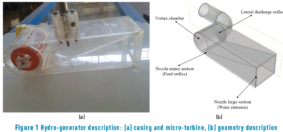
As expected, the function of the vortex chamber is to cause fluid particles to describe rotating paths since the incident flux is tangent to it. It was unknown, indeed, that the side hole would serve to evacuate water from the vortex chamber although intuitively it was assumed that this would occur because with its presence the possibility of stagnation is completely eliminated. But given the strength of the wall containing the discharge side orifice, the rotating flow in the vortex chamber had to be necessarily toward the centre and with an increasing axial component so that water could get released from the discharge orifice. This meant that for water to be continuously discharged from the vortex chamber, the particles should follow helical flow path with radial and tangential velocities decreasing toward the discharge orifice, being the maximum axial velocity at discharge.
2.2. Runner
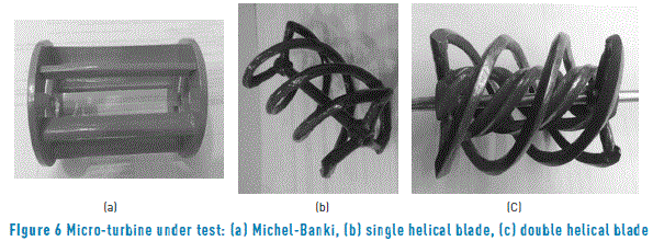
The other component of the hydro-turbine, that is, the runner, Figure 2, is the element responsible for converting the rotational energy into mechanical power vortex in the shaft thereof; therefore, its design is key in harnessing the energy that the appliance captures from the main flow. But having no history of a runner design for a helical vortex with increasing axial velocity to the outlet orifice, it was decided to test a Michel-Banki turbine-like runner, Figure 2, by the similarity of the flow on admission, but unlike the crossflow in this device, flow in the proposed machine would be rotating.
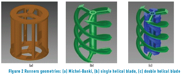
Also, for the same purpose, it was thought of two helical runners working by dragging; the first with one peripheral helical blade and the latter with a second additional central helical blade, Figure 2(c). With the latter runner, the outside of the swirling flow was meant to be harnessed, with more torque, by having larger lever arm, and the energy of the vortex core, with higher angular velocity.
3. Materials and methods
The horizontal vortex hydro-turbine of a single camera was tested in the experimental channel of the Laboratory of Fluid Mechanics and Hydraulics (LMF & H) at Universidad del Valle, Figure 3. This facility is a closed circuit having a storage tank, one pump delivering a maximum flow rate of 150 l / s, a tank water supply variable head through an internal slide gate and a channel length of 12.5 m, 0.5 m wide and 0.8 m deep. The device was sunk into the open channel at 1.5 m upstream of the open channel discharge.
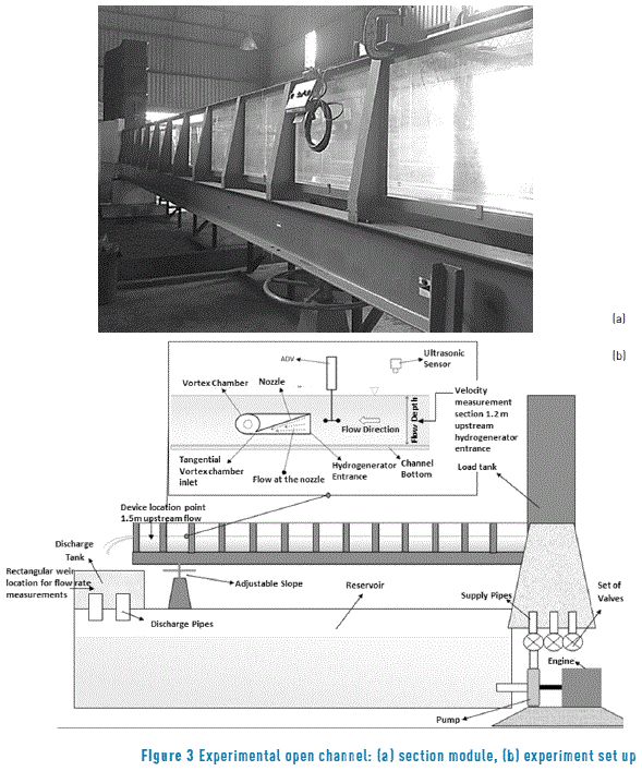
The rate of flow was measured with a triangular weir and the water level in the channel, with ultrasound equipment –Ultrasonic Flow Module 2110.
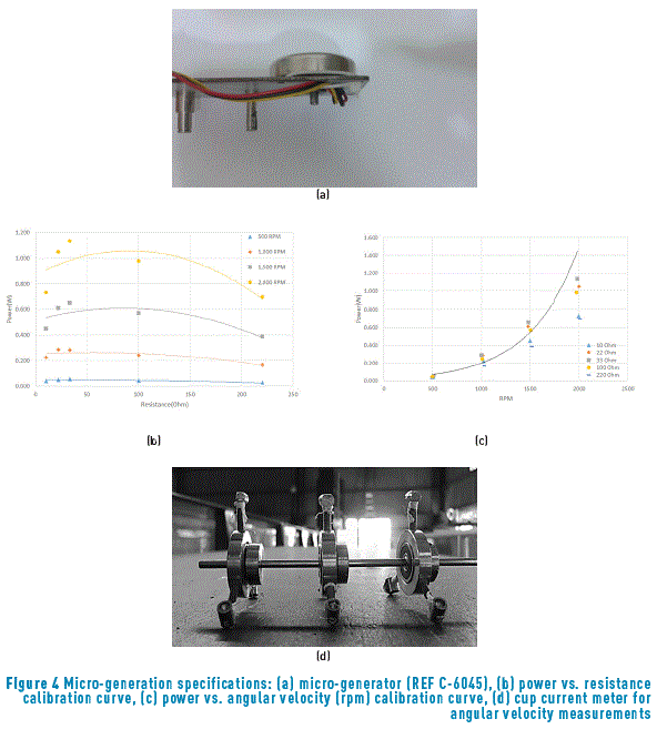
In order to measure the power generated by the apparatus, it was necessary to obtain the calibration curve of a micro generator, REF C-6045 of a watt, Figure 4(a). The maximum power that could generate this apparatus requires 2900 RPM, far from the approximate 500 RPM which at best can reach the vortex. In the absence of an intrusive device for measuring the angular velocity, a whirl-meter with three cups, with three stages and three sets of radius for measuring the speed of rotation of the vortex without runner, by using a Hall effect sensor UGN3503, was sized and built up, Figure 4(d). Voltage and currents values were measured with a voltmeter DT-9205A.
The casing measures were 0.25 m long, 0.10 m wide, discharge orifice 0.05715 m (2.25 inches) and greater and lower section heights of 0.08 and 0.01 m, respectively. These measures were obtained by testing 12 versions of the apparatus in order to find the size that reduced the effect of channel width at the water inlet. To facilitate visualization of the vortex air bubbles entering the device, the body of the hydro-turbine was made of a transparent acrylic sheet of 4 mm thick. The cylindrical shape was achieved by softening the acrylic sheet and submerging it into hot water for folding it with a cylindrical tube, in a manual process.
The construction of the three tested runners required first a drawing print of the workpiece to be built in a 3D printer– ZCorp Zprinter 405. With this print, the mold was constructed with silicone rubber or colapiscis, in which resin was poured first to obtain the runner. The blades of the Michel-Banki micro-turbine type were made with resin, and the external brackets with acrylic sheets. The runners with helical form were built with resin. This material was chosen for its resistance to tension and compression.
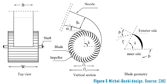
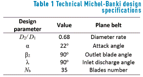
Michel-Banki turbine runner, Figure 5, was sized with the criteria by [30], Table 1 and Figure 5.
No criterion was followed in the sizing of the runners with helical blades of one and two stages because there is no information in the literature. However, its projection was made so that they operate by dragging, by following the shape of the vortex generated in the interior of the device. This concept was completely intuitive and empirical, and it is a pending task, Figure 6.
The characteristics of the Michel-Banki runner and the corresponding to the helical runner of one and two blades are shown in Table 2.
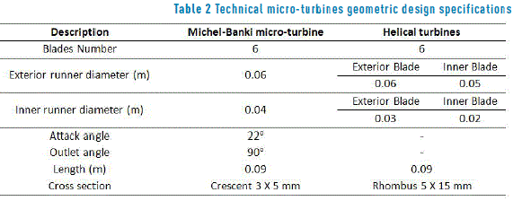
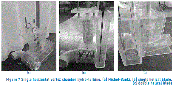
Figure 7 shows a photo of the runners – Michel-Banki, of a helical blade, and of a two-helical-blades one, installed in the hydro-turbine casing. As it can be seen, to the whole device a side box was added to avoid the action of the main flow, which slowed down the transmission system and thus the turbine.
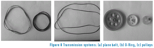
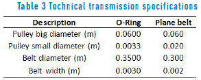
Furthermore, since the hydro-turbine is intrusive, the electrical generator was isolated with power transmission system to transfer it to the top out of the water flow. Due to market and time limitations, a system of power transmission with two gears and a band was selected, Figure 8. As shown with the characteristics in Table 3. This caused two transmission options: i) one with a transmission ratio of 1.8 to 1, with a flat rubber strip and ii) another with relation of 3.0 to 1, with an O-ring of circular cross-section acting as a band.
Since the chosen option to transmit power was not the appropriate one, because the bottom of the transmission was partially immersed in the main flow that was slowing it down, the wet section of the transmission system is isolated from the main stream with a lateral box. Although this did not prevent the transmission to operate in contact with stagnant water in the box, Figure 8.
In conducting the tests, there was no suitable wireless torque-meter available for the small torque which was expected to generate the tested hydro-turbine. Besides, in being unable to perforate the channel walls, it was decided to directly measure the electrical power generated with a micro power generator of 1 W, Figure 2. This value resulted from an approximate analysis with the integral equation of conservation of angular momentum considering the vortex chamber as control volume, with tangential feeding and axial discharge, and stationary and incompressible flow.
In essence, first, the tests involving stabilization of each of the three tested flow rates: 35.01, 102.45 and 106.14 l / s. Uncertainty measurement on flow rated was estimated according to [31, 32], this variable was measured ten times per flow rate. In each flow rate, the captured flow rate by the device was measured with a discharging pipe to the atmosphere, coupled to the discharge side orifice. Then, in order to determine the electrical power generated by the hydro-turbine in each flow rate, the current and the voltage was measured when the generator was loaded by a resistor bank 10, 22, 33, 100 and 220 ohms (Ω).
For the blunt geometry of the device, due to the lack of knowledge of its operation and the precarious instruments used, the experiment was exploratory. These factors determined that the results were not definitive, since this required improving the hydrodynamics of the device and to use non-intrusive instruments. Since it was just an exploratory experiment, it was not considered appropriate to present dimensionless results because this would imply to generalize the information obtained. This was not the main reason for the study but to determine whether the budding fluid machine could convert into electricity, at least a fraction of the flow in a channel. In these circumstances, despite the availability of data for some calculated dimensionless parameters and the uncertainty analysis performed; it was considered prudent not to present the information at the time. The authors were expecting to improve the experiment in order to present data with certain level of reliability.
4. Results
In order to assess the ability to generate electricity with the proposed hydro-turbine, when immersed in a flume and its geometry is not optimal for operation, measurements of current and voltage with each of the three tested flow rates were made to estimate the electrical generated power. Uncertainty measurement on voltage, current, and angular velocity were estimated according to [31, 32], these variables were measured five times each and three repetitions, this was for Figures 9-13.
Figure 9 shows the results of measured voltages and currents when the horizontal vortex hydro-turbine operates with Michel-Banki runner and the transmission ratio is 3: 1. In this figure, slight trends are observed, but in general there is no defined behavior of the measured variables, although the electric power was the highest for the tested largest flow rate.
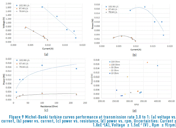
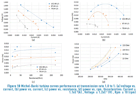
Figure 9 contains the results of the hydro-turbine runner using the runner from the Michel-Banki turbine with a gear ratio of 1.8 to 1. With this gear ratio, the variables have a clearer trend than in the previous case, being noticeable this behavior in Power vs. RPM curve, which is apparently exponential.
The operation of the hydro-turbine with a helical blade runner is described by the graphed data in Figure 10. It is the one that coverts least energy from the vortex into electrical power. Behavior charts indicate that the maximum power that was produced with the resistance of 100 Ohms and the generated power grew with the flow rate.
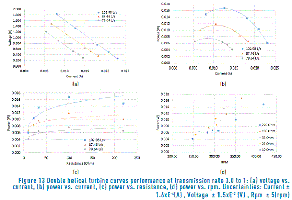
Finally, the performance of the hydro turbine with 2-helical-blade runner is seen from the information presented in Figures 11 and 12 with transmission ratio 1.8 to 1 and 3 to 1, respectively.
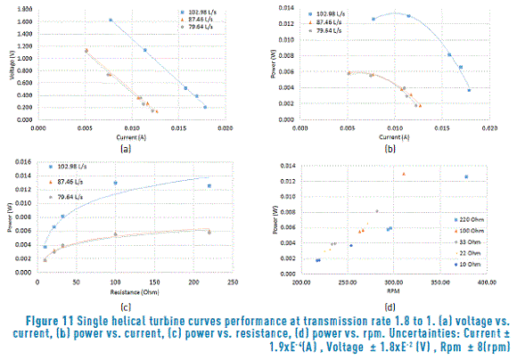
In Figure 11 it can be seen that with the ratio 1.8 to 1 hydro-turbine with 2-helical-blade runner, that it works better because a better relationship between power and current is observed, but is not the same between the power and RPM.
From Figure 12 it is evident that the ratio 1.8 to 1 had a better yield since a well-organized relation between power and current is observed. Nonetheless, it did not occur in the power and rpm plot.
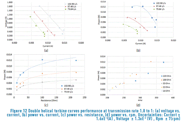
The experimental information obtained indicates that the runner with best performance was the one with the Michel-Banki turbine, originally designed to operate in a cross flow. For this reason, it is believed that no more energy was extracted from the vortex because in this one the flow is swirling. Similar behavior was observed with the double blade helical runner (Figure 13), which, in this study, was assumed incorrectly that would extract more energy from the vortex because of its similar form to the path of fluid particles in it. However, the double helix runner extracted almost the same amount of energy than the Michel-Banki turbine runner. The runner with reduced performance was the one with a single helical blade. The latter two runners with helical blades are similar to Gorlov's runner which would be appropriate for crossflow.
5. Conclusions
In this work the ability of a machine to transform the translational flow that captures in a flume into a vortex was meant to be evaluated. With this swirling flow, the runner of the device coupled to an electric generator would be triggered. The new device was conceived intuitively and is not a finished product. Rather, it is susceptible of improvements to reduce internal and external resistance to the flow that captures or develops around, in a research no longer exploratory but aimed at an assessment of their behavior.
Since the optimum operating conditions of a gravitational vortex hydro-power plant are at present unknown, despite the experimental and numerical work carried out, it would be necessary to further develop a theory for this new device tested for the first time.
Due to the blunt geometry of the device and the lack of appropriate instruments, the generation capacity of the device was assessed by measuring the current and voltage produced by a generator coupled to the runner of the machine, driven by the vortex that it forms. Taking into account the variables measured in each flow rate, the generated electrical power tested in the three hydraulic conditions was calculated.
From the results of the behavior of a single chamber hydro-turbine with horizontal vortex the following conclusions can be drawn:
- The device devised and tested in the lab is indeed able to convert flow energy into electricity.
- Due to the small size of the apparatus, the amounts of generated electrical power were minimal, although the required speed was not reached so that the electrical micro-generator used provides the maximum power according to its calibration curve.
- The generated reduced power was also the product of the used improper system power transmission.
- The transparency of the apparatus walls made it possible to see the movement of the runner and to reduce its angular velocity, as the resistive load to the electric generator was increased, so the measured voltage and current were actually generated.
- With the aid of a numerical simulation, it is possible to improve the dynamics of the vortex flow in order to redesign the system and reduce its internal and external resistance. After this, further research with other non-intrusive instruments and water pressure sensors that allow making a definitive quantitative evaluation of the test apparatus are necessary.
6. Acknowledgements
We would like to express our gratitude to the Universidad del Valle and its vice-president of research office for the support given to the research project CI 2743.
Translated by Nelson Jasac Castillo N. (Professor, Universidad del Valle).
7. References
1. F. Manzini and P. Macías, ''Nuevas Energías Renovables: Una alternativa energética sustentable'', Centro de investigación en energía / Universidad Nacional Autónoma de México, Ciudad de México, México, Tech. Rep., Aug. 2004. [ Links ]
2. S. Wanchat, R. Suntivarakorn, S. Wanchat, K. Tonmit and P. Kayanyiem, ''A Parametric Study of a Gravitation Vortex Power Plant'', Advanced Materials Research, vols. 805-806, pp. 811-817, 2013. [ Links ]
3. D. Basset, ''A historical survey of low-head hydropower generators and recent laboratory based work at University of Salford'', Ph.D. dissertation, Dept. Civil Eng., Univ. of Salford, Manchester, UK, 1989. [ Links ]
4. V. Lobo, ''Design of a vortex induced based marine hydro-kinetic energy systems'', M.S. thesis, Missouri University of Science and Technology, Missouri, USA, 2012. [ Links ]
5. C. Chang, ''Hydrokinetic energy harnessing by enhancement of flow induced motion using passive turbulence control'', Ph.D. dissertation, Univ. of Michigan, Michigan, USA, 2010. [ Links ]
6. J. Senior, ''Hydrostatic Pressure Converters for the Exploitation of Very Low Head Hydropower Potential'', Ph.D. dissertation, Univ. of Southampton, Southampton, UK, 2009. [ Links ]
7. O. Yaakob, Y. Ahmed, A. Elbatran and H. Shabara, ''A review on Micro Hydro Gravitational Vortex Power and Turbine Systems'', Jurnal Teknologi, vol. 69, no. 7, pp. 1-7, 2014. [ Links ]
8. A. Elbatran, O. Yaakob, Y. Ahmed and H. Shabara, ''Operation, performance and economic analysis of low head micro-hydropower turbines for ruraland remotes areas: A review'', Renewable and Sustainable Energy Reviews, vol. 43, pp. 40-50, 2015. [ Links ]
9. M. Khan, G. Bhuyan, M. Iqbal and J. Quaicoe, ''Hydrokinetic energy conversion systems and assessment of horizontal and vertical axis turbine for river and tidal applications: A technology status review'', Applied Energy, vol. 86, no. 10, pp. 1823-1835, 2009. [ Links ]
10. L. Lago, F. Ponta and L. Chen, ''Advances and trends in hydrokinetic turbine systems'', Energy for Sustainable Development, vol. 14, no. 4, pp. 287-296, 2010. [ Links ]
11. P. Wiemann, G. Müller and J. Senior, ''Review of current developments in low head, small hydropower'', in 32nd IAHR Conference, Venice, Italy, 2007, pp. 1-10. [ Links ]
12. S. Bozhinova, V. Hecht, D. Kisliakov, G. Muller and S. Schneider, ''Hydropower converters with head differences below 2.5m'', Energy Proceedings of the Institution of Civil Engineers, vol. 166, no. 3, pp. 107-119, 2013. [ Links ]
13. J. Johnson and D. Pride, ''River, tidal and ocean current hydrokinetic energy technologies: Status and future opportunities in Alaska'', Alaska Center for Energy and Power, Fairbanks, USA Tech. Rep., Nov. 2010. [ Links ]
14. Colorado Department of Agriculture, Applegate Group, Inc. and Colorado State University, ''Exploring the Viability of Low Head Hydro in Colorado's Existing Irrigation Infrastructure'', Applegate Group, Inc., Colorado, USA, Final Rep. 10-101, Jul. 2011. [ Links ]
15. M. Behera, X. Haihua and P. Tkalich, ''Singapore strait hydrodynamics: from ancient myths to renewable energy'', Contributions to Marine Science, National Univ. of Singapore, pp. 1-10, 2012. [ Links ]
16. Y. Lee, C. Kim, Y. Choi, I. Kim and Y. Hwang, ''Performance of a direct drive hydro turbine for wave power generation'', in 25th IAHR Symposium on Hydraulic Machinery and Systems, Timişoara, Romania, 2010, pp. 1-9. [ Links ]
17. S. Dhakal, S. Nakarmi, P. Pun, A. Thapa and T. Bajracharya, ''Development and Testing of Runner and Conical Basin for gravitational for gravitational Water Vortex Power Plant'', Journal of Institute of Engineering, vol. 10, no. 1, pp. 140-148, 2014. [ Links ]
18. S. Mulligan and P. Hull, ''Design and optimisation of a water vortex hydropower plant'', Undergraduate thesis, Inst. of Tech. Sligo, Sligo, Ireland, 2010. [ Links ]
19. H. Shabara, O. Yaakob, Y. Ahmed and A. Elbatran, ''CFD Simulation of Water Gravitation Vortex Pool Flow for Mini Hydropower Plants'', Jurnal Teknologi, vol. 74, no. 5, pp. 77-81, 2015. [ Links ]
20. C. Power, A. McNabola and P. Coughlan, ''A Parametric Experimental Investigation of the Operating Conditions of Gravitational Vortex Hydropower (GVHP)'', Journal of Clean Energy Technologies, vol. 4, no. 2, pp. 112-119, 2016. [ Links ]
21. G. Torres, ''Algunas características hidrodinámicas de un vórtice inducido en un cilindro por una corriente de agua'' Undergraduate thesis, Universidad del Valle, Cali, Colombia. 2012. [ Links ]
22. P. Kouris, ''Hydraulic turbine assembly'', U.S. Patent 6 114 773 A, Sep. 5, 2000. [ Links ]
23. F. Zotloterer, ''Hydroelectric power plant'', Austria Patent AU2003294512, Jul. 22, 2004. [ Links ]
24. M. Hallet, ''Vortex hydro turbine'', U.S. Patent 8 376 699 B1, Feb. 19, 2013. [ Links ]
25. P. Sing and F. Nestmann, ''Experimental optimization of a free vortex propeller runner for micro hydro application'', Experimental Thermal and Fluid Science, vol. 33, no. 6, pp. 991-1002, 2009. [ Links ]
26. G. Marian et al., ''The concept and theoretical study of micro hydropower plant with gravitational vortex and turbine with rapidity steps'', Buletinul AGIR, vol. 3, pp. 219-226, 2012. [ Links ]
27. H. Lugt, Vortex Flow in Nature and Technology, 1st ed. Florida, USA: Krieger Publishing Company, 1995. [ Links ]
28. S. Alekseenko, P. Kuibin and V. Okulov, Theory of Concentrated Vortices, 1st ed. Berlin, Germany: Springer, 2007. [ Links ]
29. P. Childs, Rotating Flow, 1st ed. Oxford, UK: Elsevier, 2011. [ Links ]
30. V. Sammartano, C. Aricò, A. Carravetta, O. Fecarotta and T. Tucciarelli, ''Banki-Michell Optimal Design by Computational Fluid Dynamics Testing and Hydrodynamic Analysis'', Energies, vol. 6, no. 5, pp. 2362-2385, 2013. [ Links ]
31. Instituto Colombiano de Normas Técnicas y Certificación (ICONTEC), Guía sobre la incertidumbre de la medición para principiantes, GTC 115, 2004. [ Links ]
32. Instituto Colombiano de Normas Técnicas y Certificación (ICONTEC), Medida de caudal de fluidos. Procedimiento para la evaluación de incertidumbres, GTC 170, 2008. [ Links ]
