


 Inglês (pdf)
 Artigo em XML
 Referências do artigo
 Enviar este artigo por email
 Citado por SciELO
  Citado por Google
  Similares em
SciELO
Similares em
SciELO  Similares em Google
 Permalink
1. Introduction
Radial jets have a great importance in industrial applications like heating, drying of paper, metals cooling, and recently cooling of micro-component. However, electronic manufacturers are always in search of creating more powerful and smaller devices. As a result, the heat generated during the operation of these components is higher every day, and cooling technologies are pressed to ensure a suitable heat removal for future generations of these devices.
Previous research has been conducted on the issue of radial jet, the efforts in past years were directed to the study of the influence of factor in heat transfer capability of normal configuration of jets; this research proposes a new configuration of radial jet aiming to improve the stability of fluid structure and heat transfer.
The study of impinging jets as a cooling medium holds a great significance due to increasing heat flux in electronic circuits. The jet bending degree in its path to the surface has been studied[1]; this analysis evaluates the dependence of flow parameter at different nozzle conditions such as exit angle, radius, and distance form nozzle exit to surface. Other researchers[2-7] conducted heat transfer analysis in order to describe and improve jet performance. Researchers indicated that heat transfer rate considerably improved when using radial nozzles, and in general, radial jet reattachment produces higher heat transfer coefficients than axial jets. Subsequently,[8-12] conducted studies which compared the effects of free and submerged jets in the heat transfer coefficient. Their analysis indicated that if the jet is submerged, the heat transfer coefficient can be increased up to 25%, and this ratio can vary dramatically with nozzle to surface distance.
In an attempt to increase the heat transfer from the cooling process[13], boiling heat transfer was studied as a cooling mechanism for electronic devices. Results showed that jet velocity and diameter have great influence on the heat transfer coefficient. Higher speeds lead to greater heat transfer for single-phase fluid regime while its effect on the boiling regime is not as significant for certain levels of speed. The hydrodynamic and thermal characteristics of a free jet have been researched[14] by studying the influence of the temperature and the flow velocity on jet structure. It was found that the influence of the nozzle-surface distance on Nusselt was mild, but the average Nusselt number increased with the nozzle diameter for the same Reynolds number. Three zones were identified: impingement of the jet, parallel flow and hydraulic jump area, for each one of them, the heat transfer coefficient depends on the flow rate.
In recent years[15], studies correlated and compared the rate of transfer for different radial positions and some surface nozzle distances in a submerged circular jet. Results showed that far from the stagnation point, the exponent that characterizes the flow pattern of the working fluid increases. Correlations for submerged jet as cooling systems under steady state and transient conditions were developed[16]. The study showed that the transient state is affected by the temperature rise and the flow velocity, with temperatures and high velocities easily reaching faster stability.
In addition[17], research was carried out to understand the heat transfer process in which the jet was induced by pulse. For nozzles angles ranging from 0 to 20 degrees and Reynolds from 1,683 to 2,366, air is forced to pass through a pulse supplying system, increasing heat transfer when the pulse number of the cycle is increased. For submerged jets[18], with Reynolds ranging from 10,000 to 30,000, and dimensionless distance-jet outlet surface of 0.5 to 8, it was found that for small distances between nozzle and surface (<2 diameters), peaks appear in the radial distribution of heat transfer due to abrupt increase in surface turbulence.
The structure of vortexes in radial jets when placed in front of a flat plate has also been studied[19]. Results show the influence of factors such as surface-nozzle distance and the Reynolds number in the level of vorticity in the jets. Research to observe the behavior of a modified in-line jet using a coaxial system was performed[20], the analysis reports the pressure distribution as well as the heat transfer coefficient for the jet area of influence. Experimental work[21] has analyzed the influence of jet geometry in the heat transfer characteristics. It is concluded that some geometries promote heat transfer.
All these studies show the importance of developing research in this area due to the existence of many opportunities for improvement in these systems.
2. Experimental setup
2.1. Testing system
The structure consists of an acrylic tank, 600 x 600 x 400 mm height. It has three connections, two for water recirculation in order to maintain flow conditions, and the third to deliver fluid to the nozzle, generating the radial jet. It also allows fluid extraction from the low pressure region directly below the nozzle.
A complete scheme of the testing systems is shown in Figure 1. The radial nozzle configuration is shown in Figure 2.
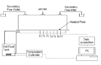
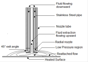
To generate the radial jet, an acrylic tube, with inner diameter of 19 mm is attached to the tank cover. A 304L stainless steel nozzle, 450 mm long, 12.6 mm outer diameter, and 8 mm inner diameter is located in the center of the acrylic tube, creating an annular flow between the acrylic tube and the stainless steel pipe. This pipe is used to extract the fluid from the area located under the radial nozzle. At one end, the tube has a 18mm diameter disc with an exit angle of 45° relative to the tube. For the impact surface, a 304L stainless steel plate, 2 mm thick is located under the nozzle. Below this plate, a heating system is located along the control system. The power supply system is also located under the plate, and it is used to provide the required power to bring the surface to the desired temperature.
2.2. Heating system
The heating system consists of two tanks. The first one with 0.5 m high and 0.25 m inner diameter has underwater electrical resistance. This electrical heater is used as the final control element in a system designed to keep the temperature at a desired value. The interface was programmed in LabVIEW to acquire the signal from a temperature sensor type LM35 which is located at the tank outlet, this signal is processed by a virtual PID controller. A 0-4 VDC system is used to power the solid state relay which allows power to be supplied to the electrical resistance to maintain the temperature set point.
The second tank has a square cross section area, 0.5x0.5m by 0.1 m in height. This tank is connected to the radial nozzle using thermally insulated hoses. It provides the fluid to the required temperature, in order to calculate the heat power transferred in the process. LM-35 temperature sensors are located at the inlet and outlet of this tank and its signal is acquired and processed through Labview.
2.3. Data Acquisition
To measure the temperature of the plate and fluid during testing, sensors type LM35 are used. These sensors essentially provide a voltage depending on the temperature of the contact surface, and this voltage is proportional to temperature (10mV equal to 1 ° C). To collect the information, a data acquisition card NI 6025E and a Labview programmed interface are used, through which the temperatures are recorded.
2.4. Experimental study methodology
For the submerged radial jet problem, the factors as well as the levels´ range are established. Also, the response variable is chosen, temperature. The experimental design is selected, and the tests are conducted (runs) to finally proceed analyzing the data and draw conclusions. The procedure used for the experiment has the following stages:
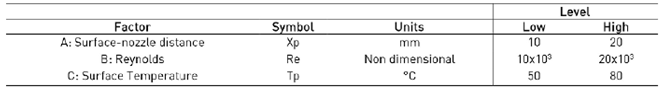
Stage 1. It is used to design the experiment to be carried out. The factors included are: surface to nozzle distance, plate temperature, and Reynolds number. In addition, there are constant factors, such as the fluid used, water; and non-controlled factors such as ambient temperature. Due to this, the entire experiment was carried out at conditioned laboratory temperature. Prior experimentation showed that the process stabilizes around 200 second, and the data was captured up to 300 seconds. From previous experiments[16], the variables range were selected. Two heights were chosen for nozzle to surface distance: 10 and 20 mm. Reynolds numbers used in the experiment process guarantee the minimum and maximum values required to generate the reattachment on the plate, 10000 and 20000. The plate temperature chosen for the experiment was based on normal operating temperatures of electronic devices: 50 to 80 °C, which represents 10.2 and 13.6 kW/m2. The response variable considered was temperature, which provides the required information about the process.
Stage 2. After defining the levels of the factors, the experimental design was chosen. The goal is to determine the significant factors. The experiment considered was a 23 factorial design, corresponding to the number of variables under study. Design Expert ® was used to randomize the experimental runs.
Stage 3. The runs are executed according the organization obtained from Design expert ®.
Stage 4. After testing completion, data analysis is developed by identifying significant factors that allow description of radial jet behavior when induced draft is used for removing fluid from the area below the nozzle.
3. Experimental model
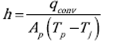
Temperature difference is related to the heat transfer coefficient as presented in Eq. (1):
 (1)
(1)
Where h is heat transfer coefficient, q
conv
is convective heat transfer,  is the heated plate area, Tp is the plate temperature, and
  is the jet temperature. The convective heat flux is calculated according to Eq. (2):
 (2)
(2)
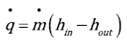
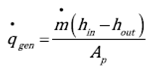
Where q gen , q cond , and q rad represent heat generated, conducted and radiated. The conduction and radiation losses are minimal. The first due to insulation employed in the system, and second because the temperatures considered in experiment are low and the temperature difference among the surfaces is quite small. Heat transfer is calculated using inlet and outlet temperatures in the heating tank. Eq. (3) to (5) present the energy balance, where h represents the fluid enthalpy:
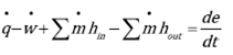 (3)
(3)
 (4)
(4)
 )(5
)(5
Nusselt number is calculated according to Eq. (6):
 (6)
(6)
Where d is the characteristic length of the flow and corresponds to the internal diameter of the stainless steel pipe. The average heat transfer coefficient is obtained from Eq. (7):
 (7)
(7)
Reynolds number is obtained from Eq. (8):
 (8)
(8)
Where u is the jet velocity evaluated at the exit of the nozzle, and ( is the kinematic viscosity evaluated at the nozzle temperature. The heat transferred to the system is given by Eq. (9):
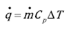 (9)
(9)
This set of equations are needed to perform the data reduction and determine the required parameters in the analysis.
4. Results and discussion
4.1. Factorial Design
To analyze the degree of significance for each factor in the phenomenon, a 23 factorial design is proposed and a random experiment is generated. Table 1 shows the factor´s levels.
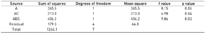
The ANOVA for Nussel shows that in the range studied, the most important factor in the response is the nozzle surface distance and its interactions with the plate temperature and the flow rate. Table 2 shows the analysis of variance for the experiment. According to the results, there is no evidence showing violation of the normality criteria, independence and homoscedasticity. It is considered that the statistical analysis is valid for the data studied.
4.2. Heat transfer cooling system
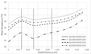
The behavior of the heat transfer coefficient when using a radial jet is well-established and is known for its advantages; however it is also known that in the area directly under the jet, heat transfer is affected by the unsteady situation created by the periodic removal of mass[1]. In this research, the fluid removal from the recirculation zone is studied in order to increase the heat transfer process while maintaining a steady condition. Figures 3 and 4 show the temperature distributions achieved when initial plate temperature is 80 °C and 50 °C respectively. It can be seen that the final temperature of the target area is lower than the rest of the plate, which constitutes an important step since it is possible to increase heat transfer in the objective area using induced draft which is the main purpose of this study.
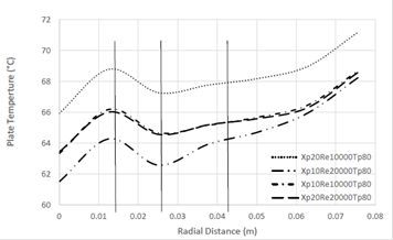
It is also noticed that there are two points with minimum temperatures. One located at the center of the plate (r = 0 m), and it is created by the fluid being removed from the bottom of the nozzle. At this condition, the fluid is able to remove a large amount of heat due to its low temperature. Furthermore, as the fluid moves from the point where it reattaches (r = 0.025m) to the center, the area is being reduced creating an acceleration in the fluid being removed through the pipe connected to the bottom of the radial nozzle. These two situations, velocity increase and low temperature help to enhance the heat transfer coefficient in this area. The flow being removed, moves upward through the center of the pipe.
The second low temperature point (r = 0.025 m) is created by the radial jet reattaching over the flat plate. The reattachment of the fluid over the heated plate, creates two boundary layers, one growing toward the center of the heated plate, while the other grows from the reattachment zone to the external radius of the heated plate. The growth of a boundary layer is associated with a maximum heat transfer coefficient due to the minimum thickness of the boundary that represents a very small thermal resistance. Considering the fluid moving from the reattachment zone (r = 0.025 m) to the center of the heated plate (r = 0 m), it is noticed that the temperature increases up to a maximum (r = 0.0 13 m), and then it decreases. The first part, (0.013 m < r < 0.025 m) presents an increase in the temperature due to the growth of the boundary layer, that increases the thermal resistance and the ability of the fluid to remove the heat. In the second part ((0 m < r < 0.013 m), the temperature decreases due to the acceleration of the fluid. The velocity increases with the negative square power of the radius (r -2 ). The fluid is considered incompressible. It is noticed, that at the first part, the governing phenomenon is the growth of the boundary layer, while in the second part, the governing phenomenon is the velocity increase and regime change, from laminar to turbulent.
Downstream (r = 0.044 m), it is noticed that the temperature presents another inflexion point that could be associated with the boundary layer turning turbulent.
The heat transfer coefficient was calculated according to the methodology presented. The values attained are presented in Figures 5 and 6.
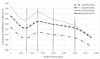
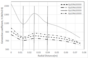
At the center of the plate, there is a conjugation of situations: the fluid moving under the nozzle has the lowest temperature due to its quick removal from the tank and allows maximizing the heat transfer from the plate; the cylindrical conditions of the phenomena implies that the minimum area is under the radial nozzle area. These two situations are combined to obtain the maximum heat transfer coefficient at the center of the nozzle. From the reattachment point (0 m < r < 0.025 m) to the center of the plate, the flow is coming radially toward the center due to the fluid removal at the central part of the nozzle. It is noticed that there is a peak (r = 0.025 m) where the radial jet impinges the plate, increasing the heat transfer due to boundary layer generation. The heat transfer coefficient slightly decreases due to boundary layer growth up to point (r = 0.012 m) where the acceleration of the fluid controls the heat transfer process, most likely turning the flow from laminar to turbulent, and at the center (r = 0 m) it reaches its maximum due to the minimum area at that point.
From the reattachment zone, increasing the radius (0.025 m < r < 0.04 m), the heat transfer coefficient decreases due to boundary layer growth. At (r = 0.04 m), it is noticed an inflexion and it could be credited to flow regimen change to totally turbulent. From that point to the end of the heated plate (0.04 < r < 0.075 m), the heat transfer coefficient decreases monotonically due to boundary layer growth, reaching its minimum value at the border of the plate due to temperature increment in the heat removing fluid and the layer growth due to radius increase.
It is very important to emphasize that there are then 2 zones with favorable characteristics for heat transfer in the proposed configuration. The first coincides with the previously known theory[1-4] (0.012 m < r < 0.04 m) that describes a ring of high-speed transfer between fluid jet impacting the heated plate and creating a reattachment zone, and the second that is the product of the proposed modification which allows greater control over the temperature of the area under the jet nozzle (0 m < r < 0.012 m).
4.3. Reynolds number
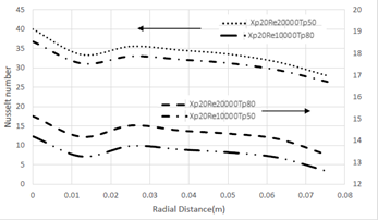
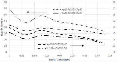
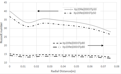
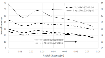
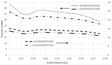
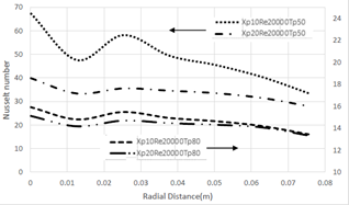
It is noticed from Figures 7 and 8 that the Nusselt number increases in all cases when the nozzle Reynolds number is increased. This was expected and has been reported by several researchers and it has been well described[3].
It is important to notice from Figures 5 and 6, that the maximum heat transfer coefficient increases quite a lot, ranging from 320 up to 1500 W/m2.°C at the center point.
4.4. Plate Initial Temperature and Power supply
For temperature, the range from 50°C to 80°C was studied. It is important to note that the initial temperature value of the plates is associated to a power supply of 10.2 and 13,6 kW/m2 respectively. The heat transfer curves have a similar trend in all experiments performed. Figures 9 and 10 show the performance for the situations under study. Again, there is a curve with a maximum heat transfer at the point under the nozzle followed by a decrease and subsequent increase when approaching point of impact with the surface.
4.5. Surface-nozzle distance
Figures 11 and 12 show Nusselt number variation. For Xp, nozzle to impact surface distance, it is noticed that the heat transfer coefficient increases while decreasing Xp from 20 to 10 which are the ranges studied. The behavior of the Nusselt number is similar for surface-nozzle distance (Xp) obtaining higher values for Xp = 10 in all configurations analyzed which is in agreement with previous research[11-16] reporting this behavior in the phenomenon.
5. Conclusions
The main parameters that determine heat transfer in a radial jet and its influence on the phenomenon have been established within statistically acceptable ranges, being surface-nozzle distance, and their interactions with the plate temperature and the flow rate, the most relevant variables that affect the performance of a radial jet with induced draft.
The use of fluid extraction through induced draft generated a significant increase in heat transfer in the area under the nozzle, because the extraction creates a regeneration zone that achieves heat transfer coefficients greater than those normally obtained in this type of device.
On the other hand, this study allowed finding that in general, the phenomenon behaves quite similar to a radial jet, and the induced draft only modifies the regeneration zone. This can be seen in Figure 7 to 12 which show that as we move away from the center line of the jet, heat transfer decreases, taking at least two peaks, one under the nozzle and the other at the impinging area, while in some other cases, depending on the Reynolds number, it can have an inflexion due to change in flow regime

