


 Inglês (pdf)
 Artigo em XML
 Referências do artigo
 Enviar este artigo por email
 Citado por SciELO
  Citado por Google
  Similares em
SciELO
Similares em
SciELO  Similares em Google
 Permalink
1. Introduction
In a variety of industries and processes such as oil/gas exploration and high-voltage power systems, it is of great importance to measure and control the temperature. Some measurement tasks can be carried out by using conventional electric temperature sensors such as thermocouples, junction temperature sensors, resistance temperature detectors, or thermistors [1]. Despite the importance of performing an adequate temperature control in situations like those previously described, electrical apparatus must be avoided in explosive environments, or alternatively, they must comply with strict standards that allowed them to operate safely [2, 3].
Optical fiber-based temperature sensors have been the focus of intensive research due to their multiple advantages such as small size, light weight, immunity to electromagnetic interference, harsh environment tolerance, and multiplexing capabilities.
A number of sensing technologies including fiber Bragg gratings [4, 5], long period gratings [6], and various configurations of interferometers [7, 8], have been developed and studied for temperature measurement with reduced cost, increased sensitivity, or enhanced temperature range [6, 8]. Recently, interference between guided modes of optics fibers for temperature fiber sensors have been reported [7- 10].
Optical fiber interferometric (OFI) based temperature sensors offer advantages such as low-price and high temperature operation in comparison with structures using fiber gratings [6]. Michelson interferometer, for example, is one of the optical fiber interferometric configurations of great interest thanks to its inherent simplicity, which consists of two single-mode fibers spliced in such manner that there is an induced lateral offset created by placing the two fiber sections off concentricity (see Figure 1]. This configuration was shown previously to be able to determine static viscosity of oils [11]. The incident light from the proximal fiber section splits into the two arms formed by the core and the cladding of the distal fiber section, besides the splice acts as the beam splitter in the interferometer, thus the light traveling through the cladding interacts with the external medium during this forward propagation. At the distal end, there is a mirror where the light from both core and cladding reflects. The reflected light from the cladding interacts again with the external medium in its counter-propagation, and recombines with the light that traveled back through the core by the same splice that caused the split.
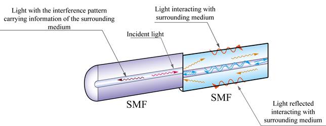
Figure 1 Sensing probe in a Michelson interferometer configuration formed by splicing two sections of SM fibers with a lateral offset (Reflection configuration)
Since normally a thick cladding shields the core mode, there is no perturbation from the surroundings on its propagation. The cladding modes on the other hand, are directly exposed to the surrounding medium and changes in its refractive index (RI) can alter significantly their effective propagation constant [12, 13].
In addition to the aforementioned, for an optical fiber the effective refractive indices of both the core and cladding change in a dissimilar manner when temperature changes. This effect is caused by a mismatch on the thermo-optical coefficients and thermal expansion coefficients of these two regions. Thus summarizing, OFI devices sense temperature changes as a sum of various phenomena: thermal expansion of the fiber, thermo-optical effect, and fluctuations in the RI of the surroundings; which, acting as a whole offer high sensitivity. However, all these phenomena also limit the use of each sensor to a specific environment. Otherwise, the sensor will have a different calibration curve (i.e. a different behavior) depending on the RI of the surrounding medium. This scenario becomes more complicated in cases where the RI of the external medium changes as temperature changes [12-13].
It is therefore necessary to develop first a technique that allows the interference spectra of an OFI device to be determined, thus allowing an adequate configuration for a temperature sensor to be designed. A later stage will require the development of techniques that provide immunity or desensitize the sensor developed in the first stage to the changes of the RI of the external medium. The last stage is then, to build a prototype of an OFI device able to measure temperature in a variety of RI media.
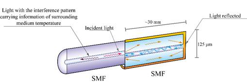
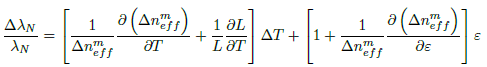
In order to isolate the RI effect from the materials properties in the sensor’s sensitivity, it is proposed to coat the probe with a gold film (see Figure 2], which in addition, serves as a mirror. The gold deposition is achieved by using the sputtering technique. In this way the cladding modes do not longer interact with the external environment, and only the effects inside the fiber optics are affected by the changes of temperature, regardless of the RI changes of external medium. Equation 1 shows the behaviour of wavelength due to changes in temperature and strain of the optical fibers.
 (1)
(1)
Where  is the center wavelength of the interference valley of the N
th
order,
is the center wavelength of the interference valley of the N
th
order,  is the free spectral range (FSR),
  is the effective RI difference between the core mode and the m
th
cladding mode, L is the interaction length, and
is the effective RI difference between the core mode and the m
th
cladding mode, L is the interaction length, and  indicates the applied strain. Both the changes of temperature and strain contribute to the wavelength shifts, which mean that the MI can be used either as temperature or strain sensor [12].
2. Experimental Setup and Methods
The configuration proposed in this work was comprised of a single-mode/single-mode (SM-SM) fiber configuration formed by splicing two sections of SM fibers (SMF-28) with a lateral offset (approximately 7 µm) in a way that the fiber’s sections were not concentric and the cores of each section partially overlap, forming a MI configuration. This setup was then coated with gold by the sputtering deposition technique. The coating thickness was approximately 10 nm, which was estimated by the sputtering coating device (Q150T Turbo-Pumped Sputter Coater). The length of the distal section of the fiber in the interferometer was 30 mm.
It is well known that lubricant oil used in automotive applications exhibits great fluctuations on its refractive index when subjected to temperature changes. This occurs as a consequence of the variation on its density and viscosity. For this reason, this type of oil was selected as the surrounding environment for the sensing probe. Two different lubricant oils, SAE 10W-40 and SAE 10W-60, were chosen since at high temperatures their viscosities are essentially dissimilar. The viscosities and densities of these oils can be found in [14].
The experimental setup employed for the temperature measurement is shown in Figure 3. Light from a SLED (superluminescent light emitting diode) was launched into the optical fiber and coupled to the in-fiber integrated MI using a 3-dB coupler. The reflected spectrum was recorded with a Bayspec optical fiber interrogator [Bayspec Inc., Fremont, CA]. A Bayspec is a fiber interrogator device designed for in-the-field measurements, whereas the more sturdy and expensive OSAs (Optical Spectrum Analyzers) are more intended for research laboratory purposes.
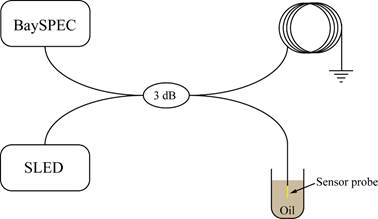
The sensing probe was immersed in the lubricant oil container while it was heated using a hot plate. The reference temperature was obtained by placing a K-type thermocouple submerged in the oil in the vicinity of the optical fiber probe. The interference pattern spectra produced from the optical fiber as temperature changes was recorded as temperature rose. Later, these spectra were analysed using MATLAB by tracking the wavelength shift of one of the interference peaks and correlating it with the temperature of the oil.
3. Results and discussion
Figure 4 shows the reflected interference patterns obtained at three different temperatures from the interferometric probe configuration shown in Figure 1, i.e. without the coating. These measurements were carried out in the SAE 10W-40 oil. Two of the recorded spectra (at the lowest and the highest temperatures) showed clear interference patterns. From Figure 4, it can also be noticed that there is a sensitivity of the interference patterns to the changes in the external medium, mostly caused by the changes in the refractive index of the oil. This sensitivity can be observed through two phenomena; firstly, the amplitude of the interference patterns was smaller for the lowest temperature when compared at the highest temperature. Secondly, there were temperatures where the peaks of the interference patterns were well-defined. Both at low (39.3°C) and high temperatures (96.9 °C). However, it was found a temperature range around 89 °C where the reflected spectrum from the fiber probe distorted to the point of causing the interference peaks to disappear. These phenomena are both attributable to the interactions of light from the fiber with the surrounding environment.
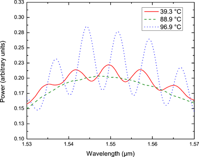
Figure 4 Reflection spectra of the sensing probe at different temperatures for an uncoated interferometer in a lubricant oil
In the first case, at low temperature, refractive index of the oil is higher than that of the glass in the optical fiber, this mismatch allows the light to propagate and counter-propagate in the waveguide formed by the core and the cladding in the MZI. However, since the external medium’s RI is higher, there are considerable losses by light that radiates to the surrounds [15]. At high temperature, on the other hand, oil’s viscosity and density drop to low values, which causes the refractive index to plummet. In this extreme case, the RI of the surroundings is lower than that of the optical fiber, thus making the light to be more confined and minimizing the losses; hence the increased amplitude in the interference pattern at the highest temperature. In between the two extreme cases there is a temperature range at which a match between the refractive indexes of the surrounding medium and the effective index of the cladding modes occurs, causing the energy of the cladding modes to become into radiating modes [15].
A different behavior was observed from the sensor probe coated with gold. The recorded spectra obtained at various temperatures is shown in Figure 5. A clear interferometric pattern is noticed at all tested temperatures. Similarly, a dependence on the spectral position of the peaks with the temperature of the external medium is observed as a red-shift. This time, there are not temperature ranges where the interference spectrum disappears, and temperature monitoring can be performed in the entire temperature range. The gold coating effectively desensitizes the interferometer probe to RI changes of the external medium. A sensitivity of 0.0054 nm/°C was calculated by tracking the wavelength position of the lowest point in the concavity of the spectra between 1.57 and 1.58 µm.
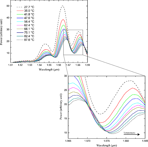
Figure 5 Reflection spectra of the sensing probe at different temperatures for a gold-coated interferometer
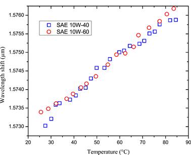
In order to prove the desensitization to refractive index changes of the gold-coated probe, its response was recorded in the two chosen lubricant oils while increasing their temperature. Figure 6 presents the wavelength shift on each case. The behaviour presented by the sensing probe showed to behave without noticeable differences despite the dissimilar environments.
4. Conclusions
Interferometric-based optical fiber sensors have shown to be reliable and accurate for temperature measurement. Most importantly, their low fabrication cost makes this type of sensors an excellent alternative for disposable sensors. In this work, a novel fiber optic temperature sensor configuration was fabricated. The sensing probe used was a single-mode/single-mode (SM-SM) fiber configuration formed by splicing two sections of SM fibers with a lateral offset, and coating it with a fine layer of gold. The sensing area located at the tip of the fiber and the measurement performed by reflection of the light makes this optical fiber probe ideal to be applied in many devices, such as engines, oil pumps, vessels, and wells, where other kind of sensors can not be installed. The sensor developed exhibited desensitization to changes in the refractive index of the external medium, which broadens the range of environments in which the sensor can measure. The temperature sensitivity obtained for this configuration was 0.0054 nm/°C. This configuration can be used in applications where a broad temperatures range is needed, and the environment can change without a calibration curve to be required.

