


 English (pdf)
 Article in xml format
 Article references
 Send this article by e-mail
 Cited by SciELO
  Cited by Google
  Similars in
SciELO
Similars in
SciELO  Similars in Google
 Permalink
1. Introduction
High penetration of distributed generation (DG) on power systems is the result of the exploitation of renewable resources (solar and wind) and other alternative forms of energy generation [1]. DG causes impacts at electrical network such as voltage variations and power unbalances [2], which pose new control challenges. To study these problems, the electrical network is divided into smaller units called microgrids (MG), a concept introduced for the first time in [3].
A micro-grid can be considered as a set of loads, generators and storage that can be managed in island or grid-connected mode in a coordinated way to supply electricity reliably [4].
MG can be generalized into two types: AC and DC. DC microgrids (DC-MG) are a promising technology for integration of electric vehicles, batteries and photovoltaic solar energy [5]. They have intrinsic advantages in terms of efficiency and controlability compared to the more conventional AC microgrids. This is because a DC-MG does not require reactive power control and/or frequency control as in the case of AC electrical networks [6]. In addition, it requires less stages of conversion and less number of cables reducing the total cost of the grid.
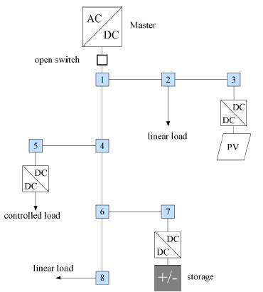
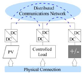
A DC-MG consists of renewable energy sources, loads and storage units connected to a dc bus as depicted in Figure 1. This type of microgrid can operate in grid-connected mode [7] as well as in island mode [8]. In the former case, it is required an ac/dc converter that fixes the voltage in a master-slave operation. In the last case, the control of the DC-MG must be coordinated in a hierarchical architecture that maintains the voltage under a limited range [9].
In general, there are three stages in this architecture namely: primary, secondary and tertiary control. The primary control brings the system to a stable operation using a droop control strategy, while the secondary control ensures system reaches the reference voltage, and the tertiary control defines the reference considering economic, and/or environmental objectives [9]. Primary control is usually local while secondary/tertiary can be designed taking into account communications among the converters.
This paper proposes a Passivity Based Control (PBC) for primary and secondary control of DC-MGs. Compared to conventional approaches, it has the following advantages: i) It unifies primary and secondary control in a single stage ii) It presents simple mathematical calculation iii) It guarantees stability considering the non-linear model of the grid.
The paper is organized as follows: section 2 presents a brief state-of-the-art about DC-MG and PBC. Next, section 3 gives the mathematical model of the grid and the control requirements. After that, the proposed PBC is described and test DC-MG is presented in section 4. Results are shown in section 5 followed by conclusions in section 6.
2. Brief review of the state-of-the-art
2.1 DC microgrids
The most common operation mode of DC-MG is the master-slave control. In this strategy, the main AC/DC converter imposes the voltage of the system and the other terminals work in maximum power point tracking at constant power or constant current [10]. This type of control is simple and guarantees stability but depends on the capability of the master terminal to maintain a constant voltage. DC-MG can separate from the main grid when a power quality disturbance occurs. In case of lost of this terminal, the DC-MG must change the operation in order to maintain stable operation. A hierarchical primary/secondary/tertiary control is used in this case to control the transition. The main dc/dc converter is master terminal and DC-MG operates in island mode. The new master controls dc-bus voltage and power flow. The surplus or deficient power must be compensated by the other elements of the network. Then, changes in the element operation are required to DC-MG stabilization. It is a cooperative control where generations, loads and energy storage units are involved. Thus, communications are necessary.
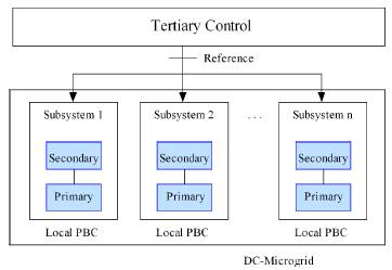
Master-slave control can be considered from the communication perspective as a centralized control. This category features by data collection from the distributed units in the master terminal to define a overall control strategy [11]. Tertiary level performs this action by means of a properly managing the energy balance in the system. Primary and secondary levels in hierarchical architecture, can be local controls as shown in Figure 2, but they need communications with upper level.
2.2 Passivity based control
There are many applications in the literature about PBC in mechanical, electrical and electromechanical systems [12]. In electricity, the two historical topics have been electrical machines and power electronics converters, specially switched power converter with constant power loads in dc/dc [13-15], nonlinear loads [16], dc/ac converter [17] and Pasivity based PI controls [18] among others. Hybrid energy control [19-22] and PBC-fuzzy logic are studied in [23] and [24]. An automotive power systems application is a PBC of a vehicular microgrid [25]. In HVDC transmission systems, passivity concept is used in modular multilevel converter control [26,27].
The problem of DC-MG stabilization is considered in few publications, where PBC is used to ensure stability of classical controls. Different stabilization strategies for DC-MG are discussed in [28], to prevent undesired effects produced by constant power loads. In that work, passivity concept is used in a PD controller. In [29], PBC theory is also used in system passivisation shaping the admittance through voltage feed forward as a modification of the classical PID.
3. Modeling and control of DC-microgrids
3.1 Modeling of DC-microgrids
The DC-MG modeling takes into account each of its elements. In the literature, different models are found depending on the control objective. Generators and storage units are commonly modeled as voltaje or current sources [30-33]. Another option is voltage sources with series resistances [32,34] and current sources with parallel resistances [34].
Loads through resistors [34], RL networks [35], current sources [30,32], current sources with parallel resistances [34] and constant power blocks [36]. The connection lines between DC buses are modeled using resistors [32,37,38], RL [36,39] and RLC models [31,40].
In the converters, RLC networks are used to operate as a filter and they serve as a coupling element with the connection lines [30,34]. In some cases, the capacitor is associated with the power converter and the impedance RL with connection line between converter and DC bus [41]. In other cases, the capacitor is located on the side of the DC bus [42]. The control action acts on the converters, so they are modeled in some cases as dependent sources [31].
3.2 Proposed model of the grid
A DC-MG is composed of a set buses  and lines
  which connect these buses. The grid in island mode can be either radial or meshed but its graph must be connected (i.e. there are not sub-islands).
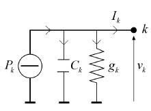
Any distributed resource such as a photovoltaic panel, a wind turbine, an energy storage device or an electric vehicle, is integrated to the grid through a dc/dc converter. These devices maintain a constant power and introduce a non-linearity which must be considered in the design of the control. Other equipments allow a constant resistance model. Therefore, each bus is represented as a constant power terminal in parallel with a capacitor and a constant admittance as shown in Figure 3. The capacitor represents capacitance of the cable plus the capacitance of the converter.
In the analysis, it is desirable to reduce the network by eliminating the nodes in which the current do not enter or leave. This procedure is known as Kron’s Elimination [43,44].  can be represented in two subsets:
  , R are nodes to eliminate and P contains nodes where current is injected. In Figure 1, subset
 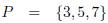 defines the equivalent DC-MG, which is shown in Figure 4. It can be noted that equivalent DC-MG has only nodes in which there are connected dc/dc converters.
P nodes form the resulting admittance matrix. Bus admittance matrix is portioned with matrices K, L and M as defined in (1).
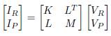 (1)
(1)
Matrix formulation can be written as (2) and (3).
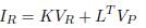 (2)
(2)
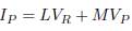 (3)
(3)
If IR = 0 then VR = -K -1 L T V P . Rewritten (3) gives (4), where it is obtained the reduced bus admittance matrix which is given in (5).
 (4)
(4)
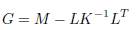 (5)
(5)
G is the nodal admittance matrix which includes the admittances of the terminals (g k ) as well as the admittances of the lines (1/r km ). Figure 5 shows the model of each node P in network equivalent.
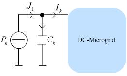
G has implicitly the interconnection information of the nodes P in the microgrid. Dynamics of each node is given by (6).
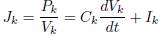 (6)
(6)
From the previous equation, the system model is obtained as indicated in (7).
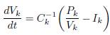 (7)
(7)
But I can be expressed in terms of G using equation I = GV. This allows a matrix representation as defined in (8),
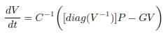 (8)
(8)
where V are the state variables, C is the capacitance matrix, G is reduced bus admittance matrix and P is a vector with the value of the controlled power in each dc/dc converter.
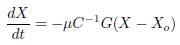
Defining V = X and P = u in (8) and simplifying yields (9).
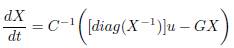 (9)
(9)
This model is general for any dc microgrid with the aforementioned characteristics. Notice, this is a non-linear system which requires a coordinated control.
3.3 Control requirements
Conventional operation of MG in island mode is based in a hierarchical primary/secondary/tertiary control. Primary control is distributed and operates without communications. It guarantees stability of the grid after the master converter is disconnected. The secondary control brings the system to a desired operative point. This can be done with or without communications. Finally, a tertiary control determines the optimal operative point according economical or environmental objectives. It is usually centralized or distributed with communications.
Primary and secondary controls can be unified in a single control with the following requirements: a) it must guarantee stability of the system and b) it must bring the system to the expected operative point.
4. Passivity based control
Energy-based modeling has been used mainly in classical mechanical systems. Euler-Lagrange and Hamiltonian representations describe energy and interconnection properties in physical systems [45]. These properties can be exploited in feedback controllers. Passivity concept allows the control systems to be analyzed as energy exchange units. It is based on energy function and dissipation structure of the systems. PBC reshapes energy of system in closed loop and forces system response a desired values [46].
4.1 Passive system
A system is passive if there exists a scalar function H(x) bounded from below, and a nonnegative function  which satisfies (10)
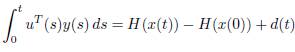 (10)
(10)
Where 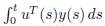 is the energy supplied to the system,
 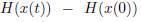 is stored and d(t) is dissipated energy. If H(xo) is a global minimum of H(x),
  and
and  will decrease in time and the system will reach x
o
asymptotically. x
o
is a natural equilibrium point.
will decrease in time and the system will reach x
o
asymptotically. x
o
is a natural equilibrium point.
There are many types of systems which fulfill this definition. We are interested in Hamiltonian system which have the form expressed in (11):
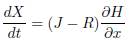 (11)
(11)
where  is the total stored energy,
  and
and 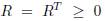 are the interconnection and damping matrices. Property: If H ≽ 0 and H(xo) is minimum, then _H ≼ 0. Hence, H qualifies as a Lyapunov function. These conditions guarantee stability [47].
An important property of passivity is the interconnection of passive systems, which yields a passive system [48]. This property is useful for microgrids where interconnection between plants and controllers exchange energy over a network. A controller must enforce the plant to change the equilibrium point to a desired value.
4.2 PBC for DC-MG
In this case, H is defined by (12):
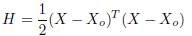 (12)
(12)
where X
o
is the reference voltages.  for proposed H is shown in (13)
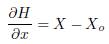 (13)
(13)
Defining null the interconnection matrix (J = 0) and using (13), the Hamiltonian system expressed in (11) can be rewritten as (14)
 (14)
(14)
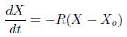
If it is defining the damping matrix as  where μ is a positive scalar associated to the speed of convergence, it is true that R ≽ 0. Then (14) is expressed as (15)
equating (9) and (15) is found the resulting control law which is given in (16).
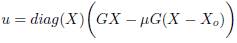 (16)
(16)
This result is a matrix formulation whose size depends on the P nodes (control nodes), as indicated in the Kron’s Elimination section. It is only possible to perform control actions at nodes where power converters are connected. In the DC-MG of Figure 1, the control nodes are 3, 5 and 7. The matrix formulation allows using the control law to any test model even complex models.
From (16), retaking the original variables (X = V and μ = P) and defining n as the number of converters that operate in island mode, it can be obtained the control signal for k node as defined in (17).
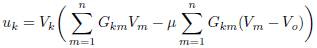 (17)
(17)
To evaluate the control law, it is necessary to know the admittances and the voltage in the converters. This control can be implemented in a distributed form. Only voltaje of dc/dc converters are required since the valued of G km are already known. This information can be exchanged by communications as depicted in Figure 4.
4.3 Test model
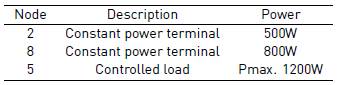
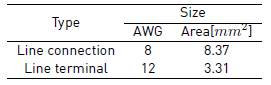
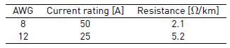
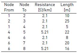
The proposed control strategy is verified by simulation. The DC-MG is depicted in Figure 1 which is composed of sources, loads and energy storage devices. The system includes a 2kW photovoltaic solar generation and an energy storage unit of 48V dc-bus voltage. Loads are described in Table 1. The DC MG has capacity to store the energy produced and supply loads in island mode. There are two line types: terminal lines for connection loads and connection lines to link sources with energy storage. Parameters of lines, cables and network elements are given in Tables 2, 3 and 4.
5. Results
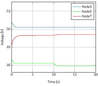
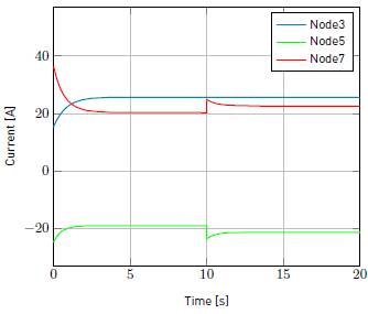
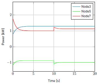
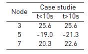
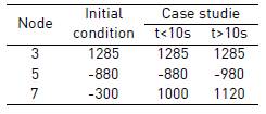
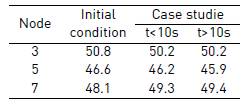
As mentioned above, a PBC performs the primary and secondary control actions of the hierarchical control levels. The tertiary control defines the reference, which is the input of the PBC proposed. Initially the grid supplies 1300W to DC-MG and the battery is charging. Then, DC-MG is disconnected and the battery must supply missing energy. This is a starting point for simulation. There are two case studies. First, it occurs in the period t < 10s, where DC-MG is stabilized after grid disconnection. In t = 10s, controlled load increases in 100W. The second case corresponds to period t > 10s, which DC-MG stabilizes again for new load conditions. State variables are voltages in nodes 3, 5 and 7. In node 3, there is a source that supplies constant power. In node 5 is the controlled load and node 7 is the energy storage system. ower values in W are included in Table 6. Simulation results show voltages, currents and powers related to interest nodes as seen in Figure 6, Figure 7 and Figure 8. It can be observed that changes in load are compensated by energy storage unit. In the case studies, DC-MG reaches a new stable operation point with damping behavior. A summary of the values of voltage in V and current in A of steady state obtained are given in Table 7 and Table 5.
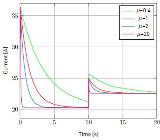
The above results were obtained by defining μ equal to 2. As mentioned, μ is a positive scalar associated to the speed of convergence. In Figure 9, current results at Node 7 are included for different μ values. Notice μ does not compromise stability, only the response time.
6. Conclusions
This paper proposed a PBC for DC-MG stabilization. The exposed properties demonstrated asymptotic stability of the controller. A Hamiltonian structure was used to obtain a desired energy function in closed loop. The proposed control strategy presented simple mathematical calculation and allowed primary and secondary control. A test DC-MG used was built in MATLAB to evaluate the dynamic performance of the controller. Simulation results shown dc-voltage regulation was achieved with good stability and damping properties.

