


 Inglés (pdf)
 Articulo en XML
 Referencias del artículo
 Enviar articulo por email
 Citado por SciELO
  Citado por Google
  Similares en
SciELO
Similares en
SciELO  Similares en Google
 Permalink
1. Introduction
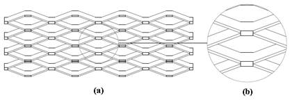
Expanded metal is a material that results from a slit and stretch process, in which a mesh is obtained in one piece without seams or welds deploying the form of diamond-shaped patterns, see Figure 1. During the slitting and stretching process, the material increases its mechanical properties as a result of plastic deformation, extending up to 10 times its original length and decreasing up to 80% (per unit area) its weight respect to its original values [1]. Besides, due to its step geometry, it provides anti-slip properties, minimizes dirt and reduces maintenance costs.
The implementation of rigid and light structures capable of supporting transverse loads has been observed in the industrial sector, usually in high locations. Such structures must have a platform configuration capable of housing and protecting equipment or people, facilitating in a safe way tasks that need to be performed on them. Although in the support area, expanded metal meshes are typically used for pedestrian traffic, these meshes can withstand heavier loads as long as they are properly safeguarded. Typical uses include platforms for machinery, floors for tanks and cargo trucks, maintenance platforms for refineries, stairs floors, and towers. Figure 2 shows some examples of expanded metal applications.
Several investigations have been devoted to study the properties and feasible applications of expanded metal meshes. Experimental and numerical studies were conducted to study the tensile behavior of expanded metal meshes [2,3]. The collapse form of expanded metal subjected to compressive loads was evaluated for specific arrangements [4]. Additionally, an empirical method was developed to estimate yield strength of bonds and strands of expanded metal meshes [5].
Recently, a series of experiments have been performed to study the collapse mechanism of multilayered expanded metal tubes subjected to axial impact [6]. Their tests showed that the mechanical behavior of expanded metal tubes depends on the size and direction of the cells. A numerical investigation was conducted on the axial crushing of concentric expanded metal tubes subjected to impact loading [7], the effect of mesh size and the impact speed on the crushing response was also analyzed.
However, there is little information regarding the behavior of expanded metal meshes subject to transverse loading. To obtain deflections in expanded metal meshes, it was necessary to create a computational parametric model in order to modify the geometry of pattern, adapting them to different models described in EMMA 557-15 Standard [8], in which various configurations are recommended when meshes are subject to transverse loading of uniform or concentrated type. These parametric models were simulated numerically using ANSYS 16 [9], a numerical software that analyzes physical phenomena by means of the Finite Element Method (FEM). Solid-type elements were used for strands and bonds in expanded metal meshes.
Next, a methodology is presented to calculate maximum load capacity that any type of expanded metal mesh can support, maintaining its structural behavior within the elastic range of the material without becoming plastically deformed, since this situation represents a failure in the structure regardless of whether it will ever fracture. Geometry, magnitude and type of loading on the meshes, and span between supports are extremely important parameters for this study. These are conditioned to the restrictions imposed by the standard for expanded metal mesh. Finally, conditions of expanded metal meshes are evaluated following the recommendations established in EMMA 557-15 Standard [8].
2. Methodology
To obtain maximum deflection in expanded metal meshes subjected to transverse loads, a parameterized model with material properties was generated. Applied loads and edge conditions were also defined. These activities are described in the following section.
2.1 Geometry of the expanded metal mesh pattern
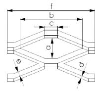
In order to investigate the influence of maximum deflection in expanded metal meshes various geometric parameters were considered:
a). vertical distance measured in the pattern inner side (short distance).
b). horizontal distance measured in the pattern inner side (long distance).
c). length of intersection between the joints of two strands.
d). strand width; represents the amount of material between openings. It is also called advance.
e). strand thickness; represents the thickness of the base material used to expand.
f). horizontal distance measured in the pattern outer side (long side of the pattern).
Figure 3 depicts the aforementioned geometric parameters.
A numerical model was elaborated using ANSYS 16 [9], a computational software that analyzes physical phenomena by means of the finite element method. In the parameterized model, coordinate key points were placed as patterns with the aim of joining them through lines. Next, the lines form rectangles whose perimeters enclose areas. Finally, these areas are extruded to construct volumes that will form the bonds and strands of the mesh.
2.2 Materials and properties
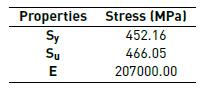
Among a wide variety of materials used in the manufacture of expanded metal meshes, ASTM A-569 low carbon steel (with a maximum value of 0.15%) and hot rolled steel is the material used for applications when a load support condition is required [8]. Values of deflections for concentrated or uniform loads were found in the EMMA 557-15 Standard [8]. Table 1 presents the mechanical properties of steel ASTM A-569, these were obtained experimentally [1]. In this investigation, tensile tests were performed for different orientations of the base metal to verify anisotropy of the material and obtain its mechanical properties, studying its influence on the model. The properties of the material used in this study are those required to simulate a linear isotropic elastic model.
In the numerical analyses, three-dimensional hexahedral solid elements were employed. These elements are generally used to mesh continuous domains and to predict accurately the actual behavior of the model. In this investigation, it should be noted that only the response of a mesh subjected to transverse loads in the elastic range of the material is studied. The solid type element selected from the program library for finite element calculation was Solid45 [9], which allows solid structure modeling. This element is defined by eight nodes, each one of them has three degrees of freedom and translations in nodal directions X, Y and Z.
2.3 Load and boundaries conditions
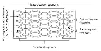
Boundary conditions suggested by EMMA 557-15 Standard [8] were applied. This standard specifies that meshes must be welded or fastened every 150 (mm), or every four patterns to a structural support as shown in Figure 4. It is always necessary to install the mesh with an orientation parallel to the distance between supports.
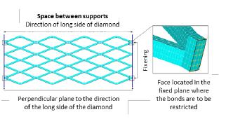
In the numerical model, the mesh was restricted every four patterns in its external bonds, as seen in Figure 5, these bonds are in surfaces located at the mesh ends. Restrictions with three degrees of freedom allowed by the element (translations in x, y, and z) are used, simulating a situation of clamped by welding. Anchors are discarded by fastening devices such as bolts and washers.
Two loading types were applied transversely to the expanded metal: uniformly distributed loads and concentrated loads. These values were obtained from the EMMA 557-15 [8]. Uniform load is the most unfavorable condition of the load, while concentrated load represents a pedestrians walking on the mesh.
Uniform loads
These are loads distributed over an entire gap between edges. Distributed loads were placed in bonds located at the top of the mesh. These bonds are the ones that receive the load in a real situation, representing the first contact points of weights placed in the sheets. Figure 6 illustrates the bonds location and the force application.
Figure 6 Uniform load applied on the mesh: (a) isometric view, (b) location of forces, (c) front view and side view
Concentrated loads
These are loads distributed over a relatively small area such as a pedestrian load or the load of portable equipment. A similar procedure to the one elaborated for uniform loads was followed, except that loads are distributed in a strip covering a central column of patterns, as indicated in Figure 7. This is a thin area with a suitable width for simulation of occasional, frequent, constant pedestrian traffic, or pedestrian traffic with light equipment.
3. Results
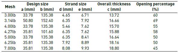
3.1 Nominal dimensions of the studied models
Table 2 shows the nominal dimensions for expanded metal meshes analyzed herein. These dimensions (whose variables are defined in Figure 3 are taken from EMMA 557-15 [8], which allows a variation of 5% of the measured values.
3.2 Distribution of forces and displacements
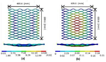
A similar pattern of stress distribution can be observed between uniform Figure 8a) and concentrated loads [Figure 8b). High stress concentrations are found in an area close to the fixing zone of the structure, specifically near the edge in which clamped bonds ends, and where strands adjacent to the fixed bonds begin. In the central zone of the mesh, a medium stress distribution is observed; the magnitude of this stress varies depending on the load type, whether is uniform or concentrated. The resulting stresses between central and clamped areas are almost negligible.
Regarding deflection due to transverse loading, it increases in magnitude from zero at the ends, to a maximum deflection located at the center. This occurs similarly for uniform and concentrated loads [Figure 9]. Magnitudes of both (stress and deflections) are not comparable because the force applied in magnitude on the mesh is quite different.
3.3 Evaluation of the mesh according to dimension
Various types of distances between supports for different denominations of expanded metal meshes were considered. Table 3 presents the results obtained in terms of stresses and deflections.
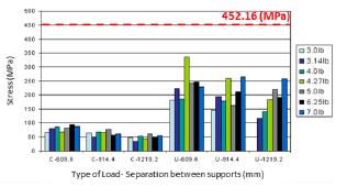
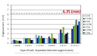
To describe the analysis and comprehension of the results obtained for different models of expanded metal meshes, a comparison of results of stresses and deflections obtained numerically with the maximum values established by EMMA 577-15 Standard [8] is performed. Figures 10 and 11 show deflections and stresses of the studied meshes. In addition, it is possible to easily observe that results obtained numerically satisfy the requirements of both maximum deflection of expanded metal meshes 6.35 (mm) and the material elastic limit used in the model 452.16 (MPa). Both boundaries are marked with dashed lines and red arrows outlined in the plots mentioned above.
3.4 Influence of the orientation of the pattern
During the installation, the orientation of patterns of expanded metal meshes on structural supports is important, in order to provide the best safety condition. Figure 12 shows the stress distribution and deflections for 3.14lb expanded metal mesh, which is clamped in orientation I (parallel to the long side of the pattern). It is seen, that maximum deflection occurs in the middle distance between supports, with a value of 0.26 (mm). It should be considered, that distribution of deflections occurs progressively from the clamped place to the middle of the mesh. At the same time, the maximum load is close to the clamped area with a value of 22.03 (MPa), and stress distribution has symmetry respect to a middle plane, neglecting them approximately in 0.21 of the spacing between supports.
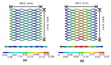
Figure 12 Numerical results for Mesh 3.14lb - Clamped Orientation I: (a) stress distribution: top and front view, (b) displacement distribution: top and front view
Figure 13 shows distribution of stresses and deflections of the expanded metal, corresponding to a 3.14lb mesh, the mesh is clamped in orientation II (in perpendicular direction to the long side of the pattern). Similar to the previous case, maximum deflection occurs in the middle of the structure; however, this value rises to 19.38 (mm) and the deflection magnitude increases by 74 times its value under the same conditions of load and distance between supports. Regarding stresses, its maximum value is located at half distance between supports and its value reaches 159.99 (MPa) and it is 7 times the value found in the previous configuration. It is evident that deflections and stresses generated in the structure increase disproportionately, considering that clamped orientation is not the most adequate for a mesh subjected to cross loads.
Figure 14 shows distribution of stresses and deflections in a 3.14lb expanded metal mesh fully clamped. It can be appreciated that maximum deflection occurs at the center of the structure with a maximum value of 0.21 (mm). In terms of stresses, the maximum value is 16.692 (MPa). As expected, the deflection and the stresses obtained are lower; however, both values are very close to the orientation I. This indicates that the best condition to fix the mesh (clamped) is the orientation I because it will significantly increase structural rigidity than orientation II.
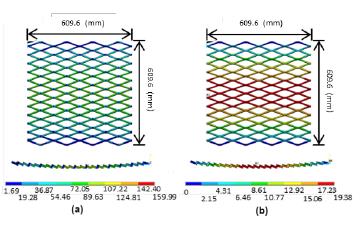
Figure 13 Numerical results for Mesh 3.14lb - Clamped Orientation II: (a) stress distribution: top and lateral view, (b) displacement distribution: top and lateral view
4. Conclusions
From the numerical study conducted herein the following conclusions are drawn:
Analyzed models of expanded metal meshes, attained deflections below the maximum recommended value of 6.35 (mm). This value is only for pedestrian comfort outlined in the EMMA 557-15.
For suitable geometries, expanded metal meshes are able to support loads up to 3905.51kg regardless if the load is uniform or concentrated.
The strength of the expanded metal sheets subjected to transverse loads depends on the distance between the supports, a smaller distance between supports represents a greater resistance of the structure.
Results obtained with a clamped structure in orientation I, are more convinient than a clamped structure in orientation II. Regarding the fixed situation in orientations I and II, this configuration offers a slight improvement with respect to the fixing in orientation I, however, a higher installation cost is assumed due to the need for a greater number of links related to structural supports (welding or bolt-type fastening devices).
For situations in which the loads are light (i.e. pedestrian loads, manual loads, etc), expanded metal meshes present a reliable and extremely economical solution, since a sheet is obtained in one piece, without joints or welds, offering anti-slip properties and great resistance.
Recommendations for further research:
Validating the results and extend the investigation, it is convenient to perform experimental analyzes with expanded metal mesh subject to transverse loads.
Investigating the effect of clamping of meshes: application of other fastening devices such as bolts, and the design of structural supports that adequately receive loads imposed on the meshes.
Analyzing the behavior of a structure subjected cyclic loads, checking its resistance to fatigue, and consequently, its service time.

