


 English (pdf)
 Article in xml format
 Article references
 Send this article by e-mail
 Cited by SciELO
  Cited by Google
  Similars in
SciELO
Similars in
SciELO  Similars in Google
 Permalink
1. Introduction
Horizontal flow sedimentation has been used in numerous water treatment applications. This process is based on the relationship between horizontal area and the surface loading rate or capture velocity of the clarifier. Usually, sedimentation tanks are designed with a capture velocity according to the Equation (1), showed below [1]:
where Vc is the capture velocity, Q is the total flow rate and As is the plan surface area.
Another parameter required for sedimentation is the terminal velocity (Vt), which is defined as the final velocity that a falling particle reaches when a force balance is achieved. Terminal velocity of particles is calculated based upon Stoke’s law for spherical particles (Equation (2)). Since the real shape of the particle is not a perfect sphere, a correction factor is used in the calculation [2].
where g is acceleration due to gravity, d is the diameter of the particle, Cd is the drag coefficient, ( floc ( floc is the density of the flocs, ( water is the density of water.
The performance of the sedimentation tank is set by the capture velocity. Floc with a terminal velocity less than the capture velocity (v c ) can be captured by sedimentation tank [1] if flow distribution is uniform.
Furthermore, some considerations in horizontal flow sedimentation tanks by Schulz & Okun includes the capture velocity has to be low enough to allow the settling velocity of the particles and, to minimize re-suspension of settled particles [3]. Usually, the area of the sedimentation tank increases to achieve these objectives [1].
AguaClara designs utilize vertical flow sedimentation tanks, with the first facility built at Ojojona, Honduras. AguaClara group is aimed to improve living conditions for isolated populations, and has implemented, assessed and enhanced, several water potabilization plants in Honduras since 2006. For this reason, the evolution of actual plants should reduce effluent turbidity with no significant increment of costs. As a result, these changes focus on physical arrangements and avoid the use of high technology. Since vertical flow sedimentation can reduce the required reactor volume while maintaining similar levels of treatment [4], AguaClara adopted this technology in sedimentation processes. Vertical flow sedimentation tanks are widely used in small sewage treatment plants; because the advantages of up flow sedimentation tanks have been confirmed, such as small area and high precipitation efficiency [5].
G. Zhu et al. showed the results of a mathematical flow simulation in a vertical flow sedimentation tank and they proved that water has a uniform distribution due to the geometry of the tank [6]. The sedimentation tank efficiency improves under a velocity between 0.02 and 0.03 m/s, which helps the water spread throughout the radial range of sedimentation tanks. In addition, it was demonstrated that particle settling velocity changes with different height of the surface.
On the other hand, AguaClara found that the most desirable upflow velocity of raw water should be in a range between 1.04 - 1.27 mm/s [1]. The difference between the results provided above by Zhu et al. and the results reported by Hurst et al., lies in the creation and stabilization of a fluidized bed of flocs called floc blanket. Floc blanket is created inside AguaClara tanks; which according to Gregory, Head & Graham, improves the efficiency of sedimentation process and dramatically decreases settled water turbidity [7].
The improved performance in AguaClara vertical flow tank design reduced plan view area and decreased turbidity of settled water due to a formation of a fluidized bed of suspended flocs colliding at the bottom of the tank. These collisions allow for many of the smallest flocs to create new bigger are more easily captured by the plate settlers [8]. Additionally, inside a floc blanket, the particles can change composition over time, as it increases particle-particle interactions that lead to flocculation and filtration occurring [9]. Research by Hurst, et. al found that the lowest settled water turbidity after a floc blanket and tube settlers was achieved at flow velocities around 1.2 mm/s [1].
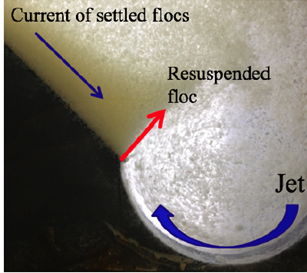
Thus, water enters to sedimentation tank, after being subjected to a flocculation process and, particles are directed to the tank inlet through diffusers in the inlet manifold. Diffusers create a line source of fluid for a uniform distribution. Once water flow enters to the HRS tank, water and particles are directed up flow to be suspended inside the floc blanket, because of the use of a jet reverser at the bottom of the tank, as can be seen in Figure 1. A current of settled flocs slides down the sloped bottom. When the current of settled flocs meets the jet, flocs are resuspended. Immediately, particles in the water start to interact and as they collide, they form bigger particles that may settle to the bottom of the floc blanket. These new bigger particles are then resuspended by vertical jet of incoming flocculated water to be part of the floc blanket [10], while smallest particles escape from the floc blanket and are directed to plate settlers. Some of these particles are captured by settlers and start to slide down again to floc blanket or to the bottom of the tank, reducing the turbulence of effluent water.
Moreover, plate settlers are used in the sedimentation process to improve the performance of both, horizontal and vertical flow tanks [10]. The inclined plates increase the efficiency of particle capture while the required plan surface area of the constructed tank decreases [11].
The technology of plate settlers relies on the theory that particles need to settle down in a surface, which in a traditional sedimentation is the bottom of the tank; but any surface with a horizontal component can be used to increase the capture area of the tank. [5]. It is important to note that the efficiency of a single particle settling depends on the total horizontal area available for settling. Plate settlers can increase the horizontal area by a factor of 10 or more [5]. These plates capture particles that escape from the floc blanket and slide down back to the floc blanket, as shown in Figure 2. Tarpagkou et. al. documented the comparison between the efficiency for a traditional sedimentation tank and sedimentation using lamellar settlers at the top of the tank. They found that the particle concentration is lower at the bottom of the tank with no settlers; on the other hand, due to the use of inclined plate settlers, particles slide down again to the bottom of the tanks, making the flow denser. The efficiency in a traditional tank and a tank with plate settlers were 14% and 75%, respectively [12]. Al-kizwini et al., demonstrated that the best inclination for the settles is at 30º angle, thus the basin used increased sediment removal efficiency [5].
Accordingly, it can be said that the use of inclined plates as plate settlers enhance the effective surface area for particle settling, as a consequence, the horizontal area in the bottom of the tank decreases, reducing the footprint of the design. Plate settlers also allow the tank to be more efficient and cost-effective [12]. Since this technology strongly reduces water turbidity, it has been widely implemented in AguaClara designs after flocculation process. [1].
The main objective of this study was to create a representative model of AguaClara sedimentation tank to analyze effects of different variables during the sedimentation process at lab scale analysis. One of the most relevant variables is up flow velocity of raw water, for that reason the performance of high rate sedimentation tank was evaluated due to the increase of velocity. In addition, since plate settlers improve the performance of sedimentation, the effects of plate settlers were analyzed in sedimentation process inside a floc blanket and its contribution to improve water quality.
2. Experimentation
2.1 Design of the laboratory tank
The laboratory-scale sedimentation model was built following the original parameters of Agua Clara upward flow sedimentation tank. Since the geometry of this tank does not change across its length, geometry was chosen to create a tank with the representative cross-sectional area characteristics and with a relative small width. Moreover, since the tank is symmetrical about the tank centerline, the flow from one half of the tank can represent the whole.
The 60 degree sloped bottom of the original tank was replicated and was attached to a jet reverser at the entrance of the tank. Figure 3 below shows a comparison between the full-scale tank and the model.
One of the goals was to create a model with good visibility and accessibility. As a result, the tank was built using clear PVC and the sludge hopper was moved from the centerline to one side of the tank.
As can be seen in Figure 3, the AguaClara sedimentation tank [Figure 3.a) has two sloped bottoms, a center pipe for the water inlet from the flocculator; while the scale model tank, in [Figure 3.b), only has one sloped bottom, and water inlet is located at one side of the tank. However, both the full scale and laboratory model have similar characteristics such as upwards flow, outlet at the top of the tank and a sloped bottom. The laboratory model was designed to replicate the behavior of the municipal scale tank.
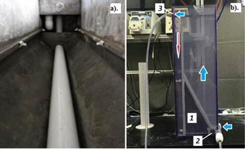
Figure 3 a) Side view of HRS tank in Moroceli Plant, Honduras (AguaClara, 2014); b) A scale model tank with the insert [1], jet reverser [2] and outlet [3]. Blue arrows show water flow direction and red arrow shows the flow of sludge to the sludge hopper in the model [10]
Since the model only represents half of the real tank, the entrance of flocculated water also changed. While the original tank has the inlet pipe in the centerline with diffusers downwards, the experimental tank has the entrance in one side of the tank with horizontal flow. In the original design, water flows down and is redirected upward by the jet reverser. In the laboratory model, the water flows upward to resuspend settled flocs from the floc blanket.
2.2 Experimental set up
Following steps used by the AguaClara group in water treatment processes, the experimental set up involved addition of coagulant and flocculation before sedimentation. Figure 4 shows a schematic of experimental apparatus. Clay and coagulant were added to tap water, then the water passed through the flocculator and finally it entered the sedimentation tank. During the process, inlet and outlet turbidity were measured continuously by inline HF Scientific turbidimeters.
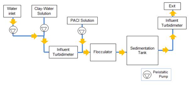
Water with a turbidity of 100 NTU was treated in the experiment. To obtain this turbidity, a relation of 60 g of clay per liter of water was used during the experiment and the turbidity was controlled by the inlet turbidimeter.
A solution of polyaluminum chlore PACl was added as coagulant at a concentration of 1.55 mg of PACI per liter of water to simulate the conditions of flocculation in AguaClara plants.
The outlet turbidimeter was located at the outlet of tank to take continuous measurements of clean water quality, while a manual turbidimeter provided turbidity measurements inside the floc blanket for each velocity and each condition of plate settler location.
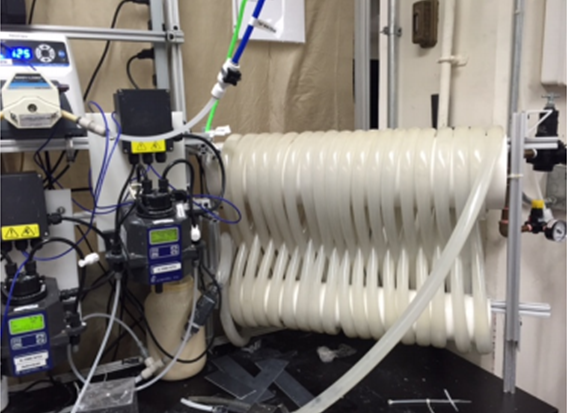
The flocculator was constructed using 7/8 in. (2.2 cm) nominal diameter tubing and a total length of 27.6 m. The tubing was wrapped around two 6 in. (15.2 cm) pipes (nominal diameter) in a figure eight for better mixing and to achieve an energy dissipation of 8.7 mW/kg. To avoid settling of particles, the orientation of the flocculator was as shown in Figure 5.
2.3 Evaluation of parameters
The parameters selected to evaluate the performance of the high rate sedimentation tank were vertical velocity and location of plate settlers. All other parameters remained constant and were similar to values used in AguaClara water treatment plants.
Upwards flow velocity
Water flowed through the entrance of the HRS tank at 1 mm/s, 2 mm/s and 3 mm/s. A peristaltic pump controlled the velocity. As the velocity of the flow changed, the dosage of the clay and the coagulant changed using peristaltic pumps as well to maintain constant concentrations.
Floc blanket concentrations
Floc blanket concentrations were measured at three velocities: 1 mm/s, 2 mm/s and 3 mm/s using a portable turbidimeter. Samples of 1 mL were diluted by a factor of 20 to 50 (depending upon the need of dilution as maximum turbidimeter reading is 1100 NTU) and then the turbidity was measured.
Effect of location of plate settlers
Different conditions were tested inside the sedimentation tank to evaluate the effect of plate settlers in particles sedimentation. Experiments include plate settlers inside the floc blanket and tank without plate settlers. Each condition was tested at each velocity.
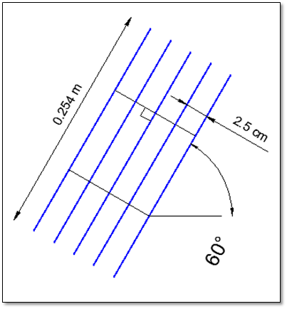
The arrangement of plate settlers had a set of parallel plates of 0.254 m length made with polyvinyl chloride (PVC) sheets of 1/16 inches (1.59 mm) thickness. The plates spacing was 2.5 cm and the plates were oriented 60 degrees from the horizontal as shown in Figure 6. This configuration increased the projected horizontal settling area by a factor of 5 and thus gave a capture velocity of 0.4 mm/s when the upflow velocity was 2 mm/s.
3. Results and discussion
3.1 Plate settlers influence
Figure 7 depicts floc blankets formed inside the tank for two case experiments. Figure 7.a) shows the floc blanket formed without plate settlers inside the tank and Figure 7.b) shows the floc blanket with plates at the top. One can see that an interface of clear water and the floc blanket was formed below the level of the sludge weir when plate settlers are installed, while the interface in the tank without plate settlers is formed at the same level of the sludge weir. Floc blanket in Figure 7.b) also seems to be denser and, it is possible to observe the effect of plate settlers on the redistribution of flocs inside the tank.
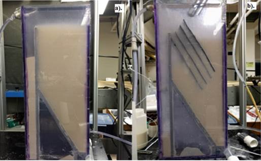
Figure 7 Shows in a) the floc blanket formed without plate settlers at an upwards velocity of 2 mm/s, compared with b) where the floc blanket is formed with plate settlers at the top of the tank at an upwards velocity of 3 mm/s
Furthermore, a quantitative comparison between the case in which plate settlers are used and when they are not used is presented in Figure 8. It is clear that effluent turbidity in the first case present lower values than when plate settlers are not installed.
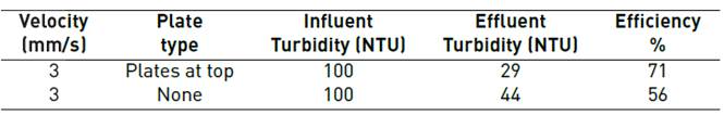
As can be seen in Table 1, the average effluent turbidity values for the first case is 29 NTU, while the effluent turbidity without plate settlers is 44 NTU, in same conditions of influent turbidity and velocity. This result could be attributed to the capture of particles by the plates; as a result, the particles slide down to the floc blanket and possibly increase the particle-particle interaction.
Average values for effluent turbidity were obtained by continuous measurement by inline HF Scientific turbidimeters at the outlet of the sedimentation tank. As a result, the turbidity removal efficiency is higher with plate settlers at top, a value of 71% was obtained versus an efficiency of 56% for no plate settlers installed. The value for plate settler arrangement fit with results obtained by Tarpagkou et al., were an efficiency equals to 75% was registered for a sedimentation tank with plate settlers at top.
In contrast, an efficiency equals to 14% was obtained for a traditional tank by Tarpagkou et. al, while the tank with floc blanket formation analyzed in this study had a greater efficiency (56%). It demonstrates the formation of a floc blanket allows the tank to improve the sedimentation process.
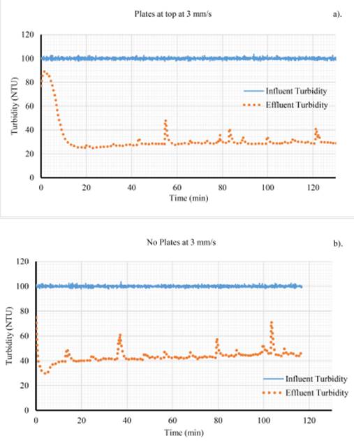
Figure 8 Influent and effluent turbidity over time at 3 mm/s. a). Plate settlers at the top and b). with no plate settlers
3.2 Flow velocity impact
Finally, for the evaluation of the effects on HRS tank performance due to increasing of flow velocity, three cases were evaluated. Experiments with same conditions of influent turbidity and plate settlers at top were run at 1 mm/s, 2 mm/s and 3 mm/s. Figure 8.a) and Figures 9.a) and b) depict values of influent and effluent turbidity response over time at 1, 2 and 3 mm/s, for an arrangement of plate settlers at the top of the tank.
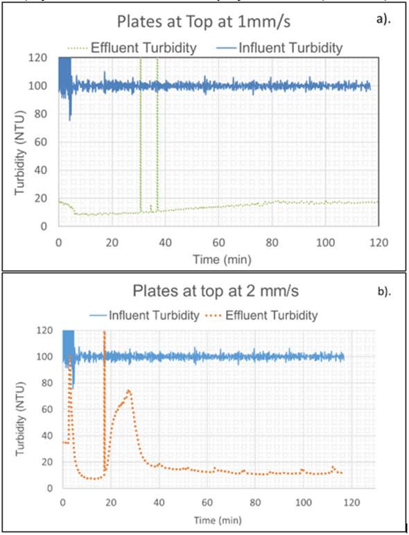
Figure 9 Turbidity (NTU) profiles vs time of treatment at different up-flow velocities for a). inflow velocity of 1mm/s and b). inflow velocity of 2mm/s, and plates at top in both cases
In all 3 cases the value of influent turbidity was 100 NTU. The effluent turbidity was different for each velocity: for a flow velocity of 1mm/s average effluent turbidity was 15 NTU, for 2mm/s an average of 18 NTU was obtained and for 3mm/s the average effluent turbidity was 29 NTU. These values correspond to an efficiency of removal of 85%, 82% and 71%, respectively. The lower value of effluent turbidity corresponds to 1 mm/s velocity (15 NTU), which means the higher turbidity removal of 85%. This result coincides with analysis carried out by Hurst, et al., were at velocities around 1.2 mm/s the lowest water turbidity was obtained. These results also validate the design parameter for upflow velocity range between 1.04-1.27 mm/s used by AguaClara. One can confirm that as upwards velocity increases, effluent turbidity increases.
However, since the difference in turbidity removal efficiency values between two consecutive velocities is relatively small, it seems that the use of plate settlers improves the stabilization of the floc blanket at higher velocities.
The creation of super dense flocs inside flocculator was observed in this experiment, however these flocs appear to have different dimensions inside HRS tank. These particles probably were broken at the inlet manifold of the tank, and this could be a possible reason for the high values of turbidity in the experiment, compared with the outlet turbidity in real tanks.
4. Conclusions
Although the lab-scale model of the sedimentation tank was intended to model a municipal scale sedimentation tank it did not achieve the same particle removal efficiency. The laboratory model formed a fluidized floc blanket by using up flow rate, sloped bottom, and particle resuspension as in AguaClara plants. However, full scale plants produce settled water normally below 1 NTU (according to AguaClara reports) while in HRS tank the minimum value obtained was 15 NTU. Thus, this technology is not yet viable to be used in municipal water treatment plants and further research is needed. Nonetheless, it is a good approach to improvements on HRS tank, reducing time of concentration and increasing efficiency.
The use of clear PVC and the relocation of some parts allow visibility and accessibility in the experiments. The parts of the tank are easy to connect and the plate settlers could be moved to facilitate the adjustment of the geometry of the tank if it is necessary to develop future work.
As expected, floc blanket concentration decreased as the up flow velocity increased, showing higher concentrations for 1mm/s experiment case and unstable bed of particles for highest velocities. However, the use of plate settlers seems to stabilize the floc blanket and to develop a fluidized particles bed at higher velocities and it showed an increase in turbidity removal, from 56 to 71%. It is possible to observe that plate settlers inside a floc blanket caused preferential flow paths of particles inside the sedimentation tank, an interface of clear water and the floc blanket was formed below the level of the sludge weir.

