


 Inglês (pdf)
 Artigo em XML
 Referências do artigo
 Enviar este artigo por email
 Citado por SciELO
  Citado por Google
  Similares em
SciELO
Similares em
SciELO  Similares em Google
 Permalink
1. Introduction
Now-a-days EV is used as an alternate to the traditional transportation system due to the development of renewable energy technology and demand in fuel. There are some constraints associated with EV. They are longer charging time, lower energy density, heavy weight and lower life time of batteries. DC motors were used for EV because of its decoupling effect. But DC motors need frequent maintenance and short life time. To overcome these problems, an induction motor has been used in EV application [1].
Many of the control techniques are available for Induction Motor drive. Direct torque control offers good dynamic performance. Compared to FOC, DTC offers less dependency to machine parameter variation, easy implementation, good transient response, and ruggedness. DTC does not involve current regulation and coordinate transformation. DTC is simple and easy to implement. The motor torque and flux linkage have been controlled independently and directly by proper selection of switching voltage vectors [2].
The Shortcomings of DTC are torque ripple, current ripple and variable switching frequency due to hysteresis band in speed and flux controller. This will lead to noise and poor performance at low-speed operation. Selection of the lookup table for the voltage vector produces variable switching frequency. Space Vector Pulse Width Modulation (SVPWM) has been proposed [3] to reduce flux and torque ripples and provide constant switching frequency thereby improves the performance of the Voltage Source Inverter (VSI) fed IM drive.
In Variable frequency drive (VFD), IM operates at constant flux to acquire the paramount transient response. The supply of the Induction Motor through VSI induces current harmonics at low speed that will make additional losses. Losses have been reduced by optimal direct torque control (ODTC) [4]. The flux varies with the load and the current used by the machine has been reduced during acceleration and deceleration operation. It would increase the battery life and prevent its discharge which is suitable for EV.
DTC of the IM drive approach has been presented for the fast-tracking ability of rotor flux and torque. Rotor speed, Rotor-flux space vector and rotor time constant has been simultaneously determined by a sliding-mode rotor-flux observer. To eliminate load disturbances effects on the IM operation under sliding, a Sliding Mode DTC-SVM based adaptive load torque control has been proposed [5] for the three types of load like constant load torque, linear load torque, and quadratic load torque. This approach extends best performances with no load disturbances effects.
DTC and Finite Control State Predictive Torque Control (PTC) for induction motor drive have been evaluated in [6]. Both control strategies provide good performance in steady and transient states and do not require modulator. But compared to PTC, DTC method has lower computation time [6].
Approximate stator flux control (ASFC) approach has been proposed [7] to control the magnitude and speed of approximate stator flux. This method does not involve the mechanical sensors and current transducers.
The loss manipulation capabilities for deadbeat-direct torque and flux control (DB-DTFC) of IM drive system have been proposed [8]. The expected torque has been obtained at the end of each switching interval by Volt.-sec.-based inverse model. Machine losses were controlled by stator flux magnitude.
To produce maximum efficiency optimization techniques (either minimization or maximization) have been proposed [9, 10].These methods are feed-forward approach called as “Loss Model Controller” (LMC) that takes up the situation logically by appropriately modeling the losses. Another technique called “Search Controller” (SC) adopts a search technique which is a feedback approach that discovers the maximum efficiency.
Several loss minimization approaches have been broadly inspected for IM drives [11]. All these methods to a large extent optimize Induction Motor flux to minimize the loss of overall drive system and are attained either by controlling Motor torque or Motor loss model controller or search controller [12].
At each operating step, the LMCs provide the optimum flux at much quicker convergence rates, but they need the accurate information of machine parameters. Drive’s efficiency is enriched by 7 %; however, the overall complexity of the system raises harshly due to system parameter estimation. SCs decrease the machine loss and the input power at a particular load demand by regulating the flux level by physics or numerical approaches.
The search control based approaches are mostly preferred because they do not affect by the machine parameter changes. SC method has been proposed for minimization of loss in the conventional direct torque controlled IM drive. Optimization has been achieved by selecting minimum stator current at certain load torque and speed. Anyhow, this approach increases the ripple content of torque and flux. Also, loss minimization by search control based on adaptive gradient descent has been proposed to optimize the stator flux, and efficiency of 51.3% has been achieved [13]. But this approach acquires large convergence time which is not appropriate for the electric vehicles needing a fast dynamic response.
Loss minimization using both the LMC and SC techniques produces 43.58% of efficiency for 2.5 kW IM drives during fair load operation [14]. But the hybrid loss minimization techniques develop the computational difficulty. Adaptive gradient descent method needs an initial interval of uncertainty. Adaptive Quadrature Interpolation (AQI) based loss minimization approach involves large computational equations and needs an initial value of controlling quantity [15].
To overcome these problems, a new SC based on Golden Section (GS) method is proposed to search optimum flux level for loss reduction of direct torque controlled IM drive. In this present system, fuzzy logic is employed for speed control loop to improve its performance. FLC can be implemented without the need of a system model. The main requirements like fast dynamic performance and exact speed tracking of EV can be obtained by the use of FLC in an external speed control loop to generate reference torque. FLC is one of the easiest non-linear control techniques.
The proposed search control is explained in section 3. The fuzzy logic controller has also proposed in section 4 instead of a PI controller in the outer loop for best speed regulation and accurate torque reference creation. SVPWM technique is used to reduce the torque and flux ripples by preserving constant switching frequency. The proposed methodology shows the excellent performance of the DTC IM drive with reduced energy loss and improved overall drive efficiency. The proposed methodology is simulated in MATLAB/Simulink and investigated with experimental results to verify the performance and the results are discussed in section 5.
2. Induction motor drive
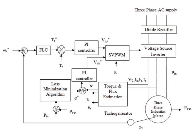
The Fuzzy Logic based Direct Torque Controlled Induction motor drive with proposed loss minimization approach is presented in Figure 1. The stator phase voltage and phase current of an induction motor are measured and using these values electromagnetic torque and flux values are estimated for the present operating condition. The overall power losses are calculated from the input and output power of three phase induction motor. Using this power loss golden section loss minimization block optimizes the rotor flux. The fuzzy logic controller predicts the reference torque value from the speed error. The actual and reference values of torque and flux are given to the PI controller which in turn produces the reference voltage for the SVPWM block. According to this reference voltage and rotor angle, SVPWM block generates switching pulses for the three-phase voltage source inverter. VSI controls the stator voltage and frequency to obtain the desired torque and speed. Due to the application of FLC, good speed tracking can be achieved. The proposed approach minimizes machine loss by selecting the optimal value of rotor flux.
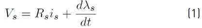
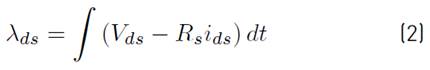
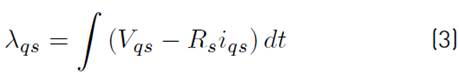
The stator voltage and flux in stator reference frame are given as Equations [(1) - (3)].
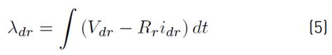
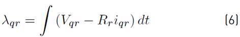
The stator voltage and flux in rotor reference frame are given as Equations [(4) - (6)].
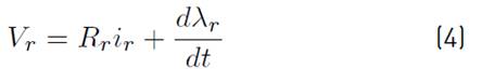
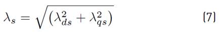
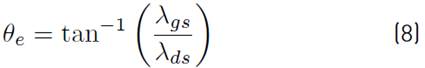
In this present work, the induction motor drive is modelled in stator reference frame. The rotor flux linkage, electromagnetic torque and rotor angle are estimated using Equations [(7) - (9)]. Rotor flux can be obtained from the rotor flux linkage.
Where,
P Number of stator poles
RsStator Resistance
RrRotor Resistance
isStator current
irRotor current
λsStator flux linkage
λrRotor flux linkage
λds and λqsStator flux linkage in d-q reference frame
λdr and λqrRotor flux linkage in d-q reference frame
VsStator voltage
VrRotor voltage
Vds and Vqs Stator voltage in d-q reference frame
Vdr and VqrRotor voltage in d-q reference frame
θeRotor angle
TeElectromagnetic torque
3. Golden section based search control method of loss minimization
For unconstrained minimization, Golden Section approach can be employed as the Line search decent method. In this golden section algorithm, the initial optimum value x0 can be estimated by direct search algorithms. Using X0 as the starting point, the sequence of estimates x0, x1, x2 ……. are derived to define the next point by sequentially seeking from each point in a direction of descent. The procedure is stopped if either no further progress, or if a point xk is reached (for smooth functions) at which the first necessary condition (f(x) = 0 is precisely satisfied. At this point x* ( xk and xi+1 < xi is not required [16, 17].
Line search method is suitable for smooth functions. The Fibonacci search method of Kiefer and the golden section method of Walsh are favoured for poorly conditioned functions. The former method is optimal with respect to the number of function valuations needed for a suggested accuracy. Later is near optimal but considerably simple and implementation is easy.
The function which has only one maximum or minimum value is called the unimodel function [16, 17].In the Golden Section method, flux is selected as a unimodel over the interval [a, b] and has a minimum value ϕ* within the interval [a, b]. The terms ‘a’ and ‘b’ are the lower & upper value of flux respectively.
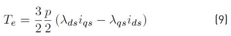
The proposed golden section algorithm is presented as a flowchart in Figure 2. The procedure involved in the GS algorithm is given below.
Golden ratio, r = 0.618034
i - Number of iteration
Initially set i=0
Length of flux unimodel, L0 = b - a
Assume minimum flux value ‘a’ is taken as 0.3Wb. The maximum flux value ‘b’ is 1.0Wb. The error tolerance of flux interval is taken as 0.05.
Interior point Flux1 and Flux2 for the golden section has been estimated as follows,
Flux1=a + r2*L0
Flux2=a + r*L0
The power loss corresponds to Flux1 and Flux2 are measured and they are Ploss1 and Ploss2 respectively.
Increase the iteration number by one.
If Ploss1 > Ploss2
Then new unimodel interval = [a, Flux2]
The Flux1 value is set to ‘a’ and Flux2 value is assigned to Flux1. The new value of Flux2 is calculated as follows,
New interval length, Li= b-a
The new value of Flux2 = a+r*Li
If Ploss2 > Ploss1
Then new unimodel interval = [Flux1, b]
The Flux2 value is set to ‘b’ and Flux1 value is assigned to Flux2. The new value of Flux1 is calculated as follows,
New interval length, Li= b-a
The new value of Flux1 = a+r2*Li
The above procedure is repeated until the length of flux unimodel is less than the error tolerance value. Once this condition is satisfied, the optimum value of flux is estimated as, optflux= (b+a)/2. The golden section method is near optimum and most straight forward method. During transient operation, the golden section method is initiated and generates optimum flux without affecting the output power. So that losses can be reduced with improved efficiency.
4. Implementation of fuzzy logic controller
In this proposed system, Mamdani type Fuzzy Logic Controller is applied in the outer speed control loop and it produces the torque reference. During disturbance conditions, Conventional PI controller exhibits poor performance at some specific speed. As compared to a conventional controller, FLC does not need an accurate mathematical model of the system and it will adjust itself corresponding to the situation. FLC has human-like thinking to produce output from the known values of input and it eliminates control issues of a conventional controller for IM. FLC is unique control techniques for uncertain and inaccurate nonlinear systems.
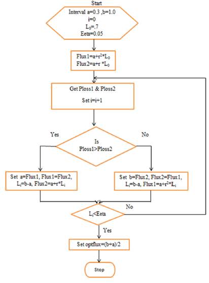
FLC consists of Fuzzification of input variables, Fuzzy inference system for the mapping of input and output variables and De- Fuzzification of output variables. Fuzzy logic membership functions are designed to enfold the whole universe of discourse. Triangular membership function involves less computation, simple and easy to implement. Therefore, the triangular membership function has been used for input/output variables. The membership functions are overlapped to get out of discontinuity with respect to the minor changes in the input/output functions. The number of linguistic variables for input and output parameters is selected from the knowledge of the induction motor drive system.
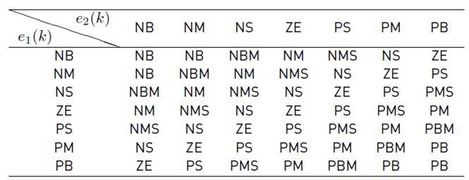
To obtain accurate control narrow region is created around the zero membership value. Wider membership functions are made away from zero regions to get a faster response of the system. Seven linguistic variables, NB (Negative Big), NM (Negative Medium), NS (Negative Small), ZE (Zero), PS (Positive Small), PM (Positive Medium) and PB (Positive Big) are selected for each input fuzzy set as given in Figure 3. To increase the resolution and accuracy eleven variables are introduced in the output fuzzy set as given in Figure 3. These are NB (Negative Big), NMB (Negative Medium Big), NM (Negative Medium), NMS (Negative Medium Small), NS (Negative Small), ZE (Zero), PS (Positive Small), PMS (Positive Medium Small), PM (Positive Medium) PMB (Positive Medium Big) and PB (Positive Big). This will enhance the dynamic behavior of the drive and produce more mature output.
After fuzzification of input/outputs variables, the fuzzy rule base is formed as given in Table 1. The Mamdani type fuzzy inference system has been used because of its intuitive property. Totally, 49 rule bases (7 x 7 = 49) are generated with fuzzy If-Then rules. Based on the rule base output variables are selected for defuzzification. The centroid type defuzzification method is used in this proposed approach.
Motor speed error e1 (k) = ωr*- ωr and change in speed error e2 (k) = e1 (k) - e1 (k-1) are the two input variables used in the proposed FLC. The reference torque is chosen as the output variable.
5. Analysis of the controllability of the system
The simulation and experimental results are compared and analyzed in this section for validating the performance of the proposed algorithm.
5.1 Simulation results
The proposed Golden Section loss minimization algorithm for Fuzzy logic based DTC of Induction Motor drive is established in MATLAB/Simulink. Figure 4 demonstrates the Simulink model of the complete drive system given in Figure 1. In Figure 4, some blocks are marked with red color arrow and circle to correlate this Simulink model with the block diagram in Figure 1. They are as follows,
Fuzzy Logic controller
Loss minimization algorithm
Torque PI controller
Flux PI controller
SVPWM scheme
Three phase VSI
Induction motor
Torque and flux estimator
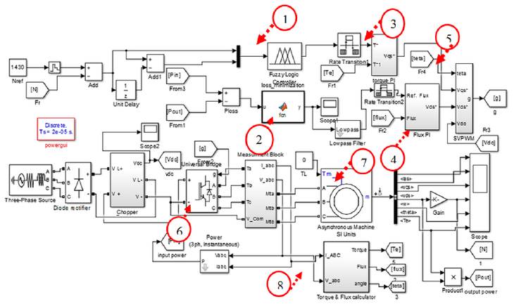
The parameters of Induction motor for simulation are given in Table 2. The induction motor model for simulation is selected from the Simulink platform.

Constant load operation
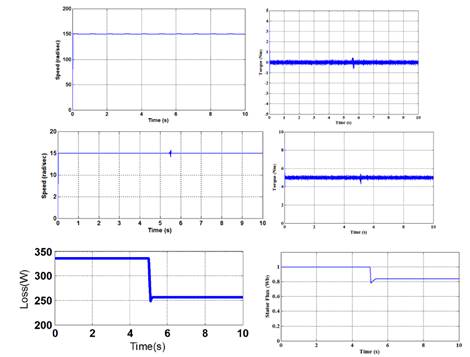
The simulation results at a rated speed of 150 rad/s with no load and the simulation results of constant speed of 15 rad/s with 5Nm load Torque is shown in Figure 5. At first, the drive operates at a constant speed and constant load torque, and subsequently the proposed loss minimization algorithm is enabled at 5.2s. Even though golden section loss minimization algorithm is enabled the drive exhibits an accurate speed tracing characteristics and achievement of load requirement which is shown in Figure 5.
As shown in Figure 5 the stator flux gets reduced considerably. At the same time stator, current is decreased. Also Figure 5 shows that IM drive’s losses are reduced by 27.1% from the initial value due to the decrease in flux value. This will increase the overall efficiency of the IM drive.
Variable load operation
Figure 6 show the speed and torque response of the proposed drive system using PI controller for variable load condition. The function of the suggested search controller for IM drive at variable load torque is shown in Figure 7. It also illustrates the exact speed tracking performance with reduced torque ripples. Comparing Figure 6 and 7, it has been proved that the accurate speed tracking is achieved by the use of FLC. The proposed loss minimization technique is activated initially at 3.1 s for the drive speed of 55 rad/s and load torque of 5 Nm. Consequently, the golden section algorithm actuates at the instance of load transition (from 5 to10 Nm) at 5 s. After the activation of the search controller at 3.1 s stator flux reaches the optimum value. Subsequently, the drive loss is declined from 349W to 302W as illustrated in Figure 7. The stator flux relaxes at a new higher optimum value. As a result, the drive loss is increased to 324W at increased load condition. The loss exaggerates due to a higher copper loss in IM to encounter the higher load torque.
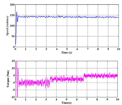
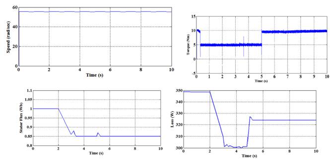
Figure 7 Simulation results of 55rad/sec Speed, variable Torque, Stator flux and Drive loss using Proposed Method
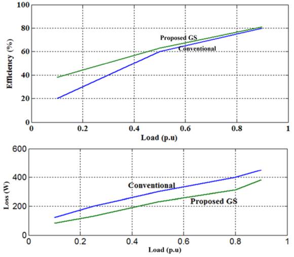
The efficiency of the IM drive with proposed search controller is inspected at various load condition. Figure 8 exhibits the efficiency comparison of the proposed drive system with conventional drive under variable load at 55 rad/s. The corresponding comparative analysis for drive loss is also illustrated in Figure 8. Core loss comes to rest at a new optimum value; however, copper loss rises for constant speed, variable load operation. But copper remains constant and core loss settles down to a new optimum value for constant load, variable speed operation. The proposed technique optimizes the flux level; therefore, drive core loss is minimized considerably.
Table 3 Performance evaluation of IM drive operation based on overall drive loss with and without optimization
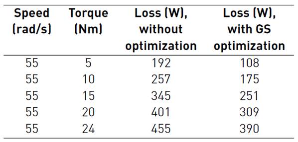
Table 4 Performance evaluation of IM drive operation based on overall drive efficiency with and without optimization
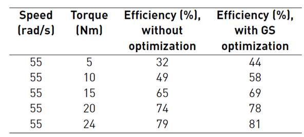
In Table 3 loss minimization is presented for different load torque at a speed of 55 rad/sec. In Table 4 efficiency assessment is presented for different load torque at a speed of 55 rad/sec. The Tables 3 and 4 review the comparative simulation results of loss minimization accomplished with GS and without optimization techniques. From the table, it is noticed that GS techniques give reduced loss pattern and increased efficiency.
5.2 Hardware results
In order to evaluate the performance of the actual system, an experimental module was designed to validate the simulation results. For the hardware implementation of the proposed Induction Motor drive, DSP controller board TMS320F28335 has been used. The proposed control scheme is compiled, transformed into C-code using CCS and involuntarily connected to the real-time TMS320F28335 processor control board. The motor parameters like speed, torque, input power, and output power are measured from the proposed drive set-up in the laboratory. Based on the measured values, the graphs are drawn for speed and torque.
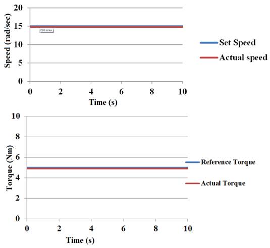
Figure 9 shows the laboratory results which confirm the simulation results as given in Figure 5. The drive achieves the accurate speed tracking with the use of FLC. Figure 9 show the experimental results at a constant speed of 15 rad/s with 5Nm load Torque.
Variable load operation
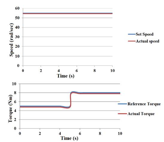
The performance of the proposed GS based loss minimization algorithm is further verified for the sudden change in load from 5 Nm to 8 Nm. at a constant speed of 55 rad/sec. The results are shown in Figure 10 illustrates that the motor speed and torque track their reference value.
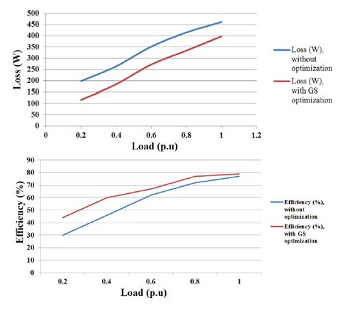
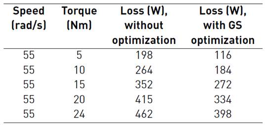
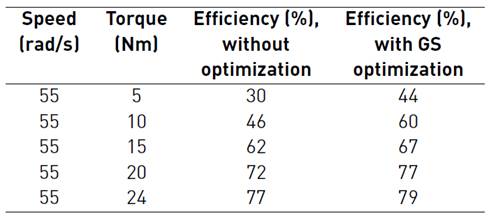
Figure 11 demonstrates the drive loss curve and efficiency curve for different load condition with and without optimization. In Table 5, drive losses is presented for different load torque at a speed of 55 rad/sec. In Table 6 the efficiency of the drive is presented for different load torque at a speed of 55 rad/sec.
In this proposed control approach, for a given load torque and a given rotor speed, the improved-efficiency has been achieved by optimizing the amplitude of stator flux. The simulation and experimental results on the drive losses and efficiency for different types of speed responses and electromagnetic torque are compared for validation and verification. It is found that the simulation and the experiment results are coordinated.
6. Conclusion
In this work, golden section algorithm of search controller for the loss minimization of Fuzzy logic based DTC of IM drive has been proposed. The proposed loss-minimization algorithm is employed in the outer loop of the drive to decide an optimum level of stator flux for the given operating condition. Subsequently, the core loss is reduced and efficiency of the drive is increased with new optimum flux. The proposed golden section algorithm is simpler compared to other optimization techniques and has a faster convergence rate (0.2s) without affecting the transient operation which is required in an EV application. DTC with FLC in speed loop reduces the torque ripples and also provides fast and good response. The algorithm is not only simple to implement but it could also reduce torque and current ripples. The proposed golden section algorithm enhances the dynamic response. IM drive with golden section algorithm has been simulated in MATLAB/Simulink and verified by the experimental results. The experimental measurements which were obtained using the experimental setup proved that the proposed method optimize the torque control process of IM drive and reduces the drive loss.

