


 English (pdf)
 Article in xml format
 Article references
 Send this article by e-mail
 Cited by SciELO
  Cited by Google
  Similars in
SciELO
Similars in
SciELO  Similars in Google
 Permalink
1. Introduction
Humans have always sought to develop tools to simplify tasks that require a lot of effort. Exoskeletons, one of these tools, act as a support mechanism that gives users enough strength to perform difficult tasks [1, 2], allows them to restore proper function of the limbs [3, 4], assist basic movements [5-8].
Over the past 50 years, the development of exoskeletons has been well documented. In the sixties, researchers at Cornell University developed a wearable mechanical system with an approximate weight of 15.8 kg called “The Superman Suit” [9]. This system allowed the user to lift a weight of up to 1000 lbs. Meanwhile, researchers at G.E. developed a two-armed handling device to manipulate radioactive material [10]. Also, around that decade, researchers at Johns Hopkins University developed an upper limb exoskeleton that helped people with paralysis perform flexion of the elbow [11].
Although these developments are well-known and plenty, advances in the military are rather few and undisclosed [12]. Even so, some examples such as the Human Universal Load Carrier (HULC) [13] or the Raytheon XOS 2 [14], (which were designed as full-bodied suits) have gathered widespread attention.
Now, exoskeletons must agree with the shape and functionality of the user's limbs. They should enhance the physical capabilities of the users and help them support loads that they would not be able to handle themselves. The goal is to bring human and machine closer so that there is a seamless integration of both [15]. In addition, the fabrication of new materials has brought forth a technological revolution whose outcome is the advancement of R+D+I [11]. Materials such as steel, alloys, and ceramics, are the focus, but advanced materials are also of interest [16].
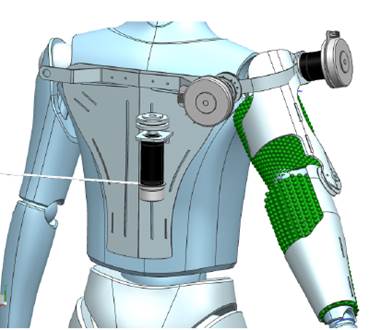
In this project, it is developed a protoype of an armored exoskeleton that improves the strength of the upper limbs, while offering ballistic protection for personal safety purpose. This was done by reinforcing the metal matrix using carbon nanotubes. Given that in this paper our focus is the design and construction of the exoskeleton, it is suggested to any reader who might be interested in the fabrication process for the protective material, to look at the cited sources [17-20].
2. State of art: wereable interactive system for the upper limb
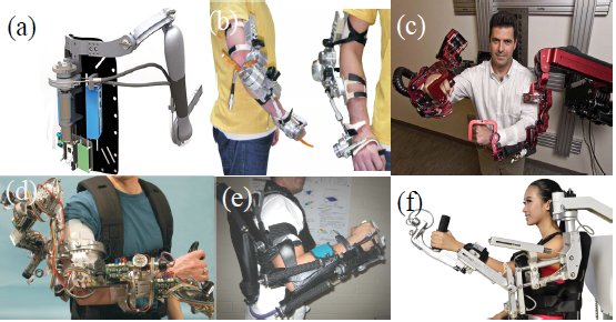
Since the sixties, projects in the industry, the military, and in healthcare have looked into the development of exoskeletons for the upper limb. Examples such as the “Titan Arm” Figure 1a, which uses electric actuators placed on the back (allowing power to be transferred toward the elbow via belts) are lightweight and practical, but lack a control system that accounts for voltage variations [1].
Other mechanisms such as the wearable orthosis for tremor assessment and suspension (WOTAS, Figure 1b) use a control system that is placed over the joint, but its overall construction is heavy, and it offers lower lifting capacity than other systems [8]. Also, the Robotic Upper Extremity Repetitive Trainer (RUPERT, Figure 1e) uses pneumatic actuators that improve the strength-to-weight ratio, but the positioning system in these is inaccurate, which is an inconvenience during rehabilitation [21]. Mechanisms such as the EXO-UL7 [Figure 1c) and the NX-A2 [Figure 1f) are used during rehabilitation, but the weight and size of the actuators in these systems actually hinders their portability [22]. Also, there are full body exoskeletons such as [23].
Finally, mechanisms such as the Sensory Arm Master (SAM, Figure 1d) use complex control algorithms to execute haptic control actions, so that the mechanism can be used remotely; this is ideal in spacefaring missions [24].
3. Desing of a linkage structure for the upper limb exoskeleton
3.1 Anatomy of the human arm
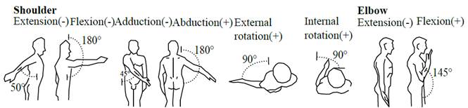
The human arm has seven degrees of freedom (DOF): three on the shoulder, one on the elbow, and three on the wrist [25]; these enable the limb to move and reach objects in a certain space following a series of movements as shown in Figure 2 [24]. The greater the number of DOF in the exoskeleton, the better the support the user gets, but too many DOF can also lead to a complex structure and increase weight, which would make the system inefficient. Thus, in this research, it was decided to overlook the loads to the wrist and simply work with three actuators considering the linkage structure in [6]: two active DOF on the shoulder, and one active DOF on the elbow, as shown in Figure 3.
3.2 Designing a structure for the exoskeleton
The structure to allow flexion and extension of the joints is designed as shown in Figure 2 and thus, it mimics the natural movements of the limb. To support flexion/extension and abduction/adduction motions, three actuators (as already mentioned) are used and considered rotation (external and internal) as performed by a passive joint (that is, not performed by an actuator).
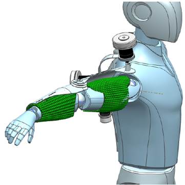
Figure 4 shows the initial design, in which actuators are placed over the joints, but after some research, there is settled for an actuator that was placed on the user's back and that transferred power to the joints using a belt and pulley system Figure 5. This design takes inspiration from the “Titan arm” Figure 1a, which integrates the structure with a shielded sheet; this design is modular, which makes the mechanism versatile.
3.3 Kinematic analysis of the proposed design
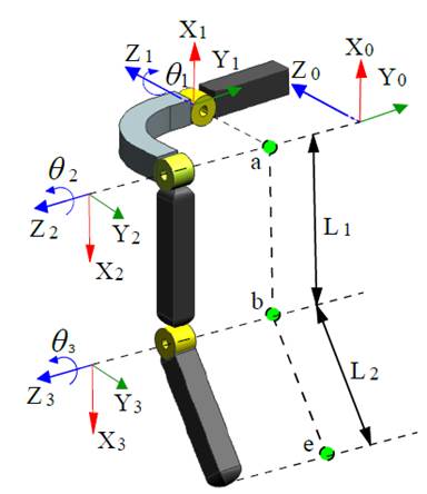
Figure 6 a shows the robotic system that is divided into two components, so that it had a wider range of motion (ROM). A geometrical estimate of a potential healthy user yielded the dimensional values of the different sections and joints [6]. According to [6], it is possible to perform a kinematic study of the arm and motions of the joints using the data presented in Table 1 and Table 2 . Then, it is considered an initial geometrical model, as proposed by Hanavan, in which an estimate of the dimensions and angles of the joints was computed using simple geometry [25]; this model is shown in Figure 6.
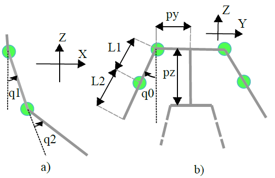
Figure 6 a) Configuration of joints q1 (flexion/extension) and q2 (elbow). Side view. b) Configuration of joint q3 (abduction/adduction). Frontal view. Data on the components is shown in Table 1
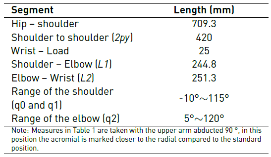
Table 1 Mechanical specifications of an exoskeleton for the upper body. Taken and edited according to the measures of one author [26]
To verify that the prototype covered all segments and mimicked the natural motions of a human arm, the exoskeleton was analyzed using forward and inverse kinematics, as described in [28].
3.4 Forward kinematic analysis of the 3-DOF exoskeleton
Forward kinematics defines the position and orientation of the wrist with respect to the base system as a function of joint variables. The position vector p
0 and the orientation vectors  were obtained by computing the transformation matrix as shown in Equation (1).
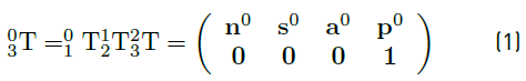
Where 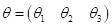 indicates the angles of each joint, and
  represents the transformation matrix from joint
  to joint
  The definition of the coordinate systems of the joints (shown in Table 3] follow the Denavit-Hartenberg (D-H) convention.
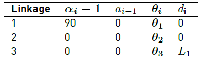
For the forward analysis, the D-H parameters are used, where 0 corresponds to the initial coordinate, there is considered for the analysis that the coordinate systems 0, 1 and 2 have the same origin and is in point α [Figure 3], and system 3 is on point  . D-H parameters are shown in Table 2. The coordinates of the final effector with respect to the fixed system
  can be computed as
  where
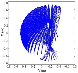
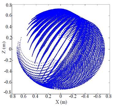
where 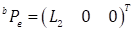 After the analysis, it is obtained the exoskeleton’s workspace (shown in Figure 7]. The lateral view of that workspace is shown in Figure 8. In this view, the (0,0,0) point of the system sits right above the center of the shoulder. 5000 points were used to build this image; the outcome is a true representation of the relative movement of the right upper limb.
4. Choosing the actuator module
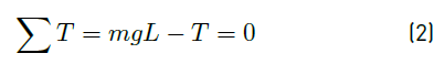
To ensure the portability of the exoskeleton, electric, D-C actuators are used. To determine the necessary torque they had to put out for move the link an angle of θ, a balanced of torques around the pivotal point for each joint is made. To do that, it is considered “the worst possible scenario”. That is, when the distance at which vector F is positioned generates the maximum torque  around de pivot point, which is calculated as indicated in Equation (2)
where m is the mass of the link, g is the gravity acceleration, and  is the distance that maximize the torque around the joint, the maximum torque was obtained when the component was positioned perpendicular to the vector of gravity force (F). As shown in Figure 9.
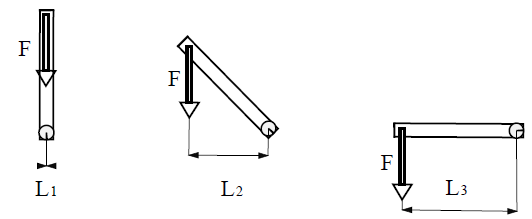
Figure 9 Variation of the effective distance produced by the torque with respect to the position of the component
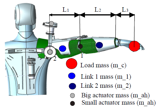
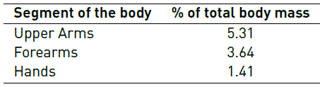
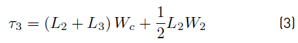
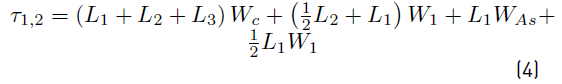
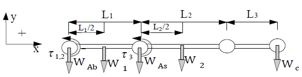
For the first actuator, the required torque was computed from the object's weight [Figure 10] times the distance to the pivot. In addition, the total mass of the component was defined as the approximate weight of the exoskeleton in this section (about 2 Kg). It is assumed that the center of mass was positioned right at the center of section  . Then, it is built a free body diagram [Figure 11] and computed the torque each motor put out so that the equilibrium be maintained, by Equations (3) and (4).
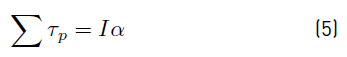
The equations presented account only for the static forces. That is, when the exoskeleton's arm is positioned horizontally. But this is not necessarily the “worst possible case”. For the arm to be able to move from a resting position, it requires acceleration. To solve the equation that takes into consideration this additional torque, we consider the rotational kinematics following the Equation (5).
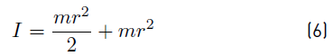
In the case of an arm, the moment of inertia is taken into consideration by rotating the arm with respect to the pivot at the tail end. Thus, the moment of inertia can be computed as indicated in Equation (6)
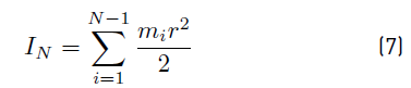
For every joint, the moment of inertia must be computed as the sum of the products of all masses times the square of the distance to the pivot (r) as the Equation (7). The mass of the actuator cannot be considered then, as it does not generate any torque with respect to its axis. In this way, r represents the distance from the center of mass to the pivot.
Given that the moment of inertia varies considerably from one component to the other, the angular acceleration is another factor that cannot be considered. According to [29], the maximum and minimal angular velocities ( ) reached by the shoulder during a daily activity was 171.5 deg/s and 16.2 deg/s and for de elbow were 172.8 deg/s and 35 deg/s. Nevertheless the power requirements for high demanded in few movements do not worth the reduction in torque. For the exoskeleton purpose in this project, where high torque is required, it is decided to stablish the maximum angular velocities for all joints in an average value of 90 °/s. Then, the angular acceleration
  can be computed using Equation (8).
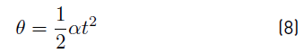
Where  is the angle traveled by the joint in a time t, solving for
  provides
  .
.
The torque that is necessary to move the arm from a resting position is calculated using the relation shown in Equation (9).

By replacing the values shown in Table 1 and Table 2 for a healthy user with a mass of 80Kg and considering a factor of safety ( ) equal to 1.1 in Equation (9) then get Equation (10)
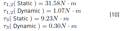
 minimum torque required by the actuator at the shoulder.
 minimum torque required by the actuator at the elbow.
There were selected two references of Maxon Motor as electric DC actuator showed in Figure 12. On the left there is a Maxon EC90Flat actuator, which was selected for the shoulder actuator, whose nominal torque  and Maxon's GP52C reference reducer has an absolute reduction ratio of
  which gives as a result a torque after the reduction of
 . On the right there is a Maxon EC45Flat actuator selected for the elbow actuator, its nominal torque:
  and Maxon's GP42C reference reducer has an absolute reduction ratio of 2401/16, performing the torque calculation with the reduction ratio is that
 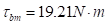 .The torques of the selected actuators
  and
and  meet the requirements of Equation (9), since
  and
and .
.
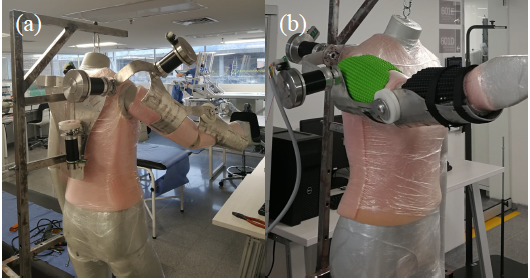
5. System assembly
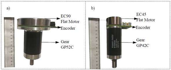
The exoskeleton and the actuator control system were integrated as shown in Figure 4 and Figure 5. shows finished assembly for the structure. The system was fitted on an articulated mannequin, and then fixed on a steel structure for protection. The power transferred to each joint was supplied by a different actuator: For the elbow, the actuator was placed on the back and then power was transferred via a belt and pulley system [Figure 13]; for the shoulder, the actuator was placed directly over the joint. All the pieces of the control system were placed on the back, (including batteries) but it is decided to used a DC power supply VRLA batteries and left the integration with ion lithium batteries for future advances. shows the assembly with the concept armor 3D printed with the exoskeleton. The assembled prototype is shown in Figure 14.
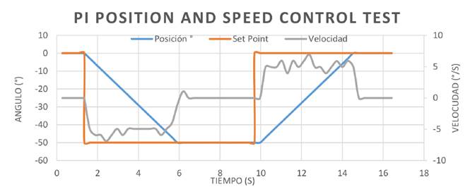
6. Control system and hardware are validation
For hardware validation, a PI position control is sintonized using the EPOS4 Compact controller from Maxon Motors. With this control system, it is possible to control position and speed. In the performed test, there the maximum speed is  (
( ) where the set point speed is around
  (
( ). The constant slope that can be observed in Figure 15 indicates that the maximum speed is fixed and this can be modified by the user at any time.
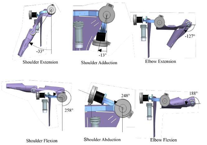
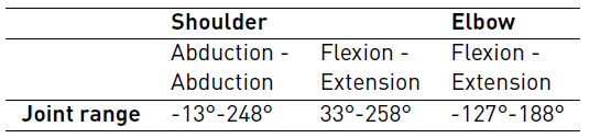
Next, the ROM that allows the built robotic system is verified, the limits in the ROM shown are given by physical factors and interference between the pieces. The articular ROM for each of the active joints in the EPMSD is shown in Figure 16 . Table 4 summarizes the results presented in the exoskeleton ROM. When comparing the ROM with the data in Table 1, it can be concluded that the exoskeleton has a suitable ROM for use by a human being. However, for safety, the electronic and control system must take into account the gap between the limits of joint movements between the user and the robotic system.
7. Conclusions and future perspectives
The structure of the exoskeleton takes inspiration from the geometry of the human body, mainly the right arm, and takes into consideration the DOFs and ROM, which were found using the kinematic analysis.
The actuator module consists of a DC motor that transfers power to the elbow via a belt and pulley system. Meanwhile, two actuators placed over the shoulder allow flexion/extension and abduction/adduction motions. To determine the torque required from each actuator, it is performed an analysis of the static and dynamic forces that affected each joint. In the future, it is expected to implement different strategies of adaptive control to have a say on the strength and positioning of the system.
There is also expected to be able to integrate impedance control into the control system, and to develop accesories that provide additional DOFs, such as in the development of systems for the lower limb. In addition, it is expected to integrate the shielding material via compo forging of aluminum and carbon nanotubes (Al/CNTs), so that we may be able to carry out performance tests in a lab setting.

