


 English (pdf)
 Article in xml format
 Article references
 Send this article by e-mail
 Cited by SciELO
  Cited by Google
  Similars in
SciELO
Similars in
SciELO  Similars in Google
 Permalink
1. Introduction
Multi-stage rotating machinery is employed today in a wide variety of industrial applications. These systems should be carefully designed to be carried out with the operational requirements that include mechanical resistance, stiffness, vibration levels, and operation speed range. A couple of essentials factors to study the vibration phenomena are first the vibration severity, mainly caused by mass unbalance, and second the proximity of the operation speed to the critical speeds, in which the resonance of the rotodynamic system is generated. A good strategy consists in controlling the negative dynamic factors from the design process to get reliable multistage rotated systems. Normally, a critical condition happens when the rotor operates near to one of its critical speeds, because in this condition the amplitude of the vibration increases.
Several investigations about rotodynamic have been focused on the prediction of rotor behavior, security, and reliability. In [1] the steady state response of an asymmetric rotor of one stage is modeled. The results let the authors conclude that the dynamic response of the rotor in a steady state to a specific speed can be precisely predicted.
Other researchers studied the critical speeds in Turbomachinery by computer simulation and contrasted the results with experimental measurements [2]. The work concludes that the accuracy of computational models in predicting critical speeds depends fundamentally on two aspects: firstly on the accuracy of the free vibration model of the rotor, which is a function of the elastic model of the latter; secondly, it depends on the accuracy in estimating the stiffness and damping coefficients of the bearings, which are a function of the turning speed in the case of fluid film sliding bearings. They also determine that the first two or three critical speeds on any rotary machine can be determined with errors not greater than 7%, as long as the linear estimation methods are correct, also, to properly contemplating the effects of rigidity and damping of the bearings.
On the other hand, the transfer matrix method has been used for study the lateral and torsional vibration of an asymmetric rotor [3]. The researchers used the Euler’s angles to describe the rotor orientations. In this research, it was established that when the torque and unbalance rotor force excite simultaneously the system, the frequencies (n-1)(X and (n+1)(X predominate as similar as the fundamental speed in the frequency domain. In [4] the same methodology to analyze the transient lateral response and the instabilities of a rotor under torsional load excitation is employed. The author concludes that the lateral effect generated by the torsional load was a minimum, even when the rotor was operating near to its critical speeds. Using this methodology [5] studied the rotodynamic behavior in the torsional direction of a typical wing (elastic) installed in a flexible shaft. The modeling results and the simulation done in this work exhibited a strong dependency and an energetic interaction between the shaft torsional distortions and the wing’s flexible distortions.
Recent investigations have showed specific results for each application. The way as the equipment with electrical power supply stimulate the torsional and lateral vibration in a turbo compressor is analyzed in [6]. While a rotodynamic analysis method that considered the coupled lateral and torsional vibration in a tandem compressor with a speed increaser is approached in [7]. In their analyses, the authors conclude that lateral vibration can be stimulated by the vibration modes of the coupled system, but this is not usually detected when an independent lateral vibration analysis is developed.
The dynamic behavior of the centrifugal fan’s rotor is analyzed in [8]. For a long time, this fan operated at 1,900 rpm, but for operational conditions, it was moved to operate at 2,080 rpm; when the change was made, then high vibration levels, more sensitivity to unbalance and finally catastrophic failures in rotor bearings appeared. One of the main conclusions was that the gyroscopic effect and the forces acting in the overhung centrifugal fan can modify in a 37% the frequency of the first modal shape.
Finally, [9] studied the behavior of compressors operating close to the critical second speed according to API specifications; however, it was not possible to accurately determine the second critical speed without considering appropriately the effect of the flexibility of the supports.
In the current work, a theoretical and experimental study of the multistage rotor behavior under lateral load excitation is done. The rotor dynamic analysis includes mathematical and experimental determination of the first and second critical speeds of the rotor and the assessment of the effects induced by the different unbalance combinations. The mathematical model considers stiffness and damping in the supports. The establishment of the lateral critical speeds begins with the mathematical approach that describes the multistage system, where the set of equations is solved using the transfer matrix method. The main contribution of this work is an integrated mathematical formulation that leads to a better prediction of the multistage rotor response under multiple imbalance conditions, both for stable and transient conditions.
Simultaneously with the synthesis of the theoretical model, an experimental installation was designed and built that allows registering lateral vibration data in the rotor, in order to obtain the spectrum and orbit diagrams in the two bearings. The experimental installation allows identifying the critical speeds of the system and analyzing the dynamic effects caused when different imbalance conditions are induced in the rotor stages. The data obtained from the experimental installation are used in the validation of the theoretical model.
2. Experimentation
2.1 Generation of the analytical model
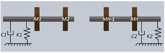
The lateral vibration model analyses start from the movement equations for a flexible system extracted from Lagrange equations. The equations describe a system composed of rigid impellers connected to a flexible shaft and supported by flexible journal bearings. The Figure 1 shows the general diagram of the multistage rotor model defined in this study.
The kinetic energy for one stage of the rotor is defined according to (1).
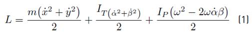
Where L is the kinetic energy of one stage of the rotor (J); ( is the rotation speed of the rotor (rad s-1); m is the impeller mass (kg); IT is the impeller’s transverse inertia moment for x or y axis (kg m2); IP is the polar moment of inertia of the impeller for the z axis (kg m2); ( is the rotation angle of the rotor relative to the y´ axis (rad); ( is the rotation angle of the rotor relative to the x´ axis (rad); and ( is the rotation angle of the rotor relative to the z´ axis (rad), respectively.
From Lagrange formulation, Equation (2) is established.
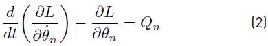
Where L is the Lagrangian, (n is a point in the configuration space of the multistage rotor and Qn is the non-conservative torque. In addition, the work is expressed by Equation (3).
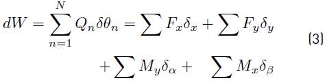
Where (i is the deformation according to the direction i (mm), Fi and Mi are forces (N) and bending moments (Nm) respectively according to the direction i.
Substituting (1) and (3) in (2), the movement of an impeller is described by Equations (4).
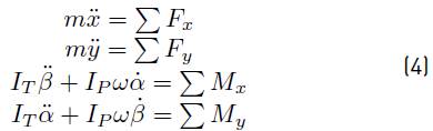
In Equations (4), the terms  and
and  describe the gyroscopic effects in the rotodynamic system. The terminology on the right side in each equation describe the friction and internal elastic forces caused for the shaft in each impeller, the unbalance forces, the flow forces and the loads in the bearings.
The forces (F x and F y ) and moments (M x and M y ) for one stage are defined by (5).
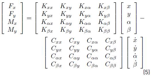
The stiffness (K ij ) and damping coefficients (C ij ) in (5) define the forces and moments in each stage in the directions x, y, α and β, respectively.
As is shown in (5), there are 16 coefficients of stiffness and 16 coefficients of damping respectively which define the forces and moments in each stage of the rotor. The elements in the diagonal of the stiffness matrix are called cross coupled effect stiffness coefficients, and they associate the unstabilize mechanism of a rotodynamic system. The solution of these matrices are complex numbers, which define the eigenvectors (real part) and eigenvalues (imaginary part) of the system. Using computational tools, the solutions to the system of equations that describes the rotor under consideration can be obtained. The formulation is developed using the approach of a system of polynomial equations for each step according. The differential equations of the polynomial system that define the lateral vibration phenomenon are written for each mass in the transfer matrix. Since the equations are linear and homogeneous, these enable to find the eigenvalues of the system through a solution of the type Xe st , as considered in [10, 11]. Thus, under this criterion, matrices of differential equations can be transformed into matrices of linear algebraic equations. The mathematical expression for each step, considering the transfer matrices referred and polynomial solution summarized by (6) and (7).
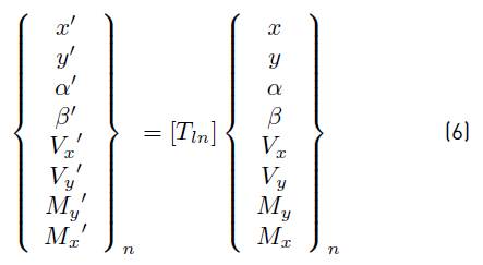
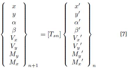
Where, [T ln ] is the transfer matrix (8x8) for each impeller or stage, and [T sn ] is the transfer matrix associated with each rotor section.
The solution of the system of polynomial equations is obtained by multiplying together all transfer matrices (one for each stage), and thus the overall transfer matrix that represents the entire multistage system is obtained, which process solution consists in first applying the boundary conditions of the rotodynamic system.
2.2 Design of the experimental model
The development of the experimental design is executed in three steps: first, the mechanical design of the physical system is accomplished, then the system configuration signal acquisition and associated instrumentation is implemented, which is necessary for recording the data inherent to the vibration phenomenon, and finally the different tests for the determination of the first two lateral critical speeds and the study of the vibrations due to the mass imbalance are planned.
To measure the lateral vibration, it was opted for using two accelerometers (CTC Ref.: AC140-3D/010/010-F, resolution: 100mV/g and connection BNC) installed orthogonally in the journal bearings. These signals are processed and analyzed by an interface developed in LabVIEW (Sound & Vibration Toolkit used V4.0 and the Toolkit Control Design & Simulation Module) for obtaining the spectrum, time waveform and orbits graphs. The multistage rotor is designed as a shaft supported by two simple supports, and up to seven stages can be installed, with the possibility of independently controlling the mass imbalance.
The experimental installation was composed of a three-phase electric motor (1.8 hp) as a driving source, two hydrodynamic journal bearings, a variable speed controller (Altivar 71) for control of the motor frequency rotation, two flexible couplings for shaft ends and two lateral accelerometers to measure the vibration signal. In Figure 2 (a), the experimental model developed for the present work is shown. In Figure 2 (b) a detail of the assembly of counterweights intended to induce mass unbalance in the different stages are shown.
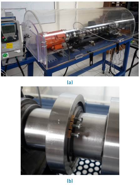
Figure 2 a) Overview of the experimental setup; b) Design detail for inducing mass imbalance in steps
The geometries and physical and mechanical properties described below are used in the theoretical model. Figure 3 shows the geometry of the seven-stage rotor on which the present research is conducted.
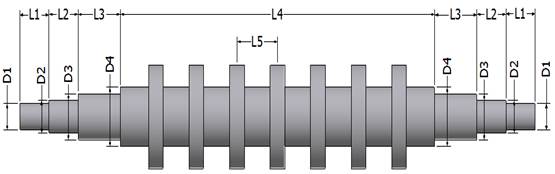
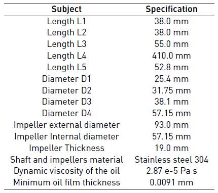
The rotor dynamic system studied comprises a rotor with seven rigid disks supported by two bearings. Disks and shaft are made with stainless steel with Young’s modulus of 193 GPa, Poisson’s ratio is 0.3 and density of 8,080 kg/m3. Table 1 shows the main parameters and geometrical features of the multistage rotor.
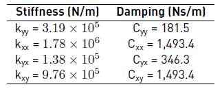
Further, the stiffness and damping coefficients are calculated according to the type of bearing, diameter, viscosity, load, speed, radial clearance and Sommerfeld number. Table 2 presents the stiffness and damping properties of the journal bearings.
Three main types of tests were planned: test to find the first critical speed; test to find the second critical speed; and finally, the vibration analysis for three different configurations of rotor mass unbalance. The test to determine the first critical speed begins with the rotor running at 30 Hz and then the frequency is increased progressively and in a controlled manner up to 80 Hz. For the determination of the second critical speed, the test begins with the rotor running at 80 Hz and then the frequency is increased in a controlled manner up to 120 Hz. On each step of rotation frequency, the wave time, spectrum and orbital position for the journal bearing locations are obtained.
The third kind of test consists of checking the vibration severity levels for different rotor imbalance condition. These tests are based on the recording and analysis of the vibration with the rotor unbalanced. The mass imbalance is accomplished by changing the orientation of the counterweights, all of mass equivalent to 6 g, in one or more of the seven stages in the rotor. The experimental conditions are: unbalance condition “A” (imbalance for the 0° position in the first stage); unbalance condition “B” (imbalance for the 0° position in the first stage, 90° position in the fourth stage, and 270° position in the seventh stage), and finally, unbalance condition “C” (imbalance for the 0° position in the third, fourth and fifth stage).
3. Results and discussion
3.1 Results for the first lateral critical speed of the rotor
According to results from the experimental model, a high instability was observed in the frequency range between 42 and 50 Hz, setting the presence of the first lateral critical speed at 46 Hz. Figure 4 shows the vibration spectrums at 46 Hz for both measurement planes, left and right journal bearings (motor side) (a) and (free side) (b), respectively.
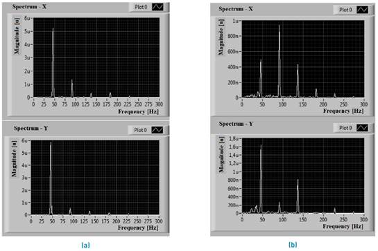
Figure 4 Vibration spectrum at 46 Hz in the journal bearings for the driven side (a) and coupling side (b)
At spectral point of view, an increase in 2.5 times in the vibration severity levels was appreciated reflecting the rotor was passing through its first critical speed. The frequency 1x was the highest for drive end bearing position, whereas in the coupling bearing side the 2x frequency has higher vibration levels. In Figure 5, the orbits described by the rotor at 46 Hz for the locations of the bearings are shown, (a) left side (motor side) and (b) right side (coupling side). The orbits of the rotor show much higher vibration amplitude for the first critical speed than for low frequencies. It can be seen an inner loop in the direction of rotation of the rotor, which is usually found in a critical speed region. Subsequently, when the rotor frequency is raised to 48 Hz, the orbits begin to experience a semielliptical behavior (more stable dynamic condition), while there is still an inner loop that reflects a slight restriction to rotation (precession).
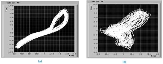
Figure 5 Orbits of the rotor at 46 Hz for the driven journal bearing (a) and for the coupling journal bearing (b) in the planes x and y, respectively
In Table 3, the values for the first critical speed obtained according to the theoretical model and recorded in the experimental installation designed are shown. The mathematical model predicts the first critical speed with an error of -6.74% relative to the experimental measurement.
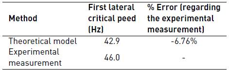
When the rotor reaches its first critical speed, it is strapped within its modal shape, this behavior is defined by mass distribution, stiffness, rotor damping and supports. A multistage rotor supported by equal rigidity bearings features cylindrical and conical modal shapes.
3.2 Results for the second lateral critical speed of the rotor
According to results from the experimental test, the greater instability in the rotor is present at a frequency of 98 Hz, corroborating experimentally the appearance of the second lateral critical speed near to this value. In Figure 6, the spectra of vibration at 98 Hz for both planes, and the locations of the left and right bearings (motor side and coupling side) respectively are shown.
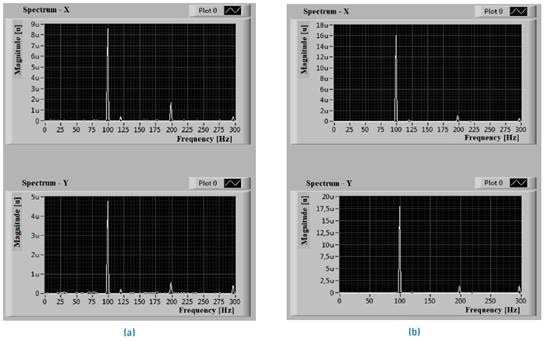
Figure 6 Vibration spectrum at 98 Hz for the driven journal bearing (a) and for the coupling journal bearing (b) in the planes x and y, respectively
In Figure 7, the orbits described by the rotor at 98 Hz for the locations of the bearings are shown, (a) left side (motor side) and (b) right side (coupling side) respectively. The orbit of the rotor in the second critical speed experiences a higher vibration amplitude behavior than intermediate frequencies (greater than the first critical speed). The orbits for the journal bearing in the driven sideshow an inner loop with eight shapes.
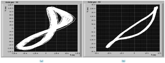
Figure 7 Orbits of the rotor at 98 Hz for the driven journal bearing (a) and for the coupling journal bearing (b)
In Table 4, the values for the second critical speed obtained according to the analytical model and the experimental facility are shown. The mathematical model developed predicts the second critical speed with an error of -12.65% concerning the experimental measurement.
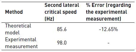
The results of the mathematical model confirm that the lateral critical speeds of the rotor are fundamentally sensitive to variations in the system stiffness and damping parameters, a decrease of 50% in the damping parameters of bearings imply that the new frequencies in which the first and second lateral critical speed appear increased by 20.7% and 10.5% respectively, compared to the frequencies initially calculated.
3.3 Results for mass imbalance in the rotor stages
Unbalance condition “A”
When the rotor rotational speed is brought up to a frequency of 76 Hz, then a severe vibration condition is observed in the motor side journal bearing. The dominant frequency is 1x for the two journal bearings positions. This condition of operation of the rotor shows the damaging effect of imbalance in the machine dynamics, typical of the appearance of the phenomenon of critical speed. In Figure 8, the orbits for the two journal bearings of the rotor, (a) drive side and (b) coupling side respectively, are shown. The orbits described by the rotor, in the journal nearest to the first stage, reflect internal loops associated with high vibration levels.
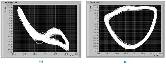
Figure 8 Orbits of the rotor for the driven journal bearing (a) and for the coupling journal bearing (b), with mass imbalance in the first stage at 76 Hz of rotation frequency
The maximum error found for the multistage rotor model using the transfer matrix method that contemplates the mass imbalance effect is -10.6% relative to the experimental value. This is attributed to the considerations taken when setting the frequencies for data collection in the experimental measurement.
Unbalance condition “B”
When the rotor rotational speed reaches the frequency of 80 Hz, an effect of structural resonance not associated with the onset of the critical speed is experienced, since the orbit graph presents vibration amplitudes somewhat lower than those found in the first test of imbalance (condition A). This indicates the effect of dynamic instability resulting from imbalance induced in the rotor. In Figure 9, the orbits for both journal bearings positions at 80 Hz, (a) drive side and (b) coupling side respectively, are shown.
Unbalance condition “C”
When the rotor rotational speed is brought up to a frequency of 65 Hz, an increase of 2.5 times in the rotor vibration level was experienced for both journal bearings positions, regarding their vibration parameters concerning the balanced rotor. These results are consistent with [12].
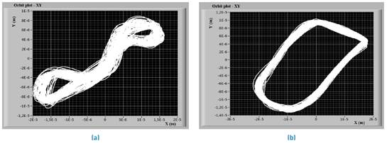
The graphs of orbits allowed recording a loop; while in the time graphs a modulation of the vibration signals, for both velocity and displacement units, were registered. In Figure 10, the orbits for both journal bearings locations of the rotor, (a) drive side and (b) coupling side respectively, are shown.
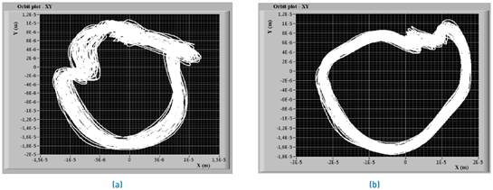
Figure 10 Orbits of the rotor for the driven journal bearing (a) and for the coupling journal bearing (b), with mass imbalance in the third, fourth and fifth stages in phase at 65 Hz of rotation frequency
According to the experimental results, it is concluded that the mass imbalance leads to move to higher values the magnitudes of the critical frequencies when these are compared with the critical speeds for the case of a balanced rotor.
This phenomenon is one of the main situations faced by the turbomachinery designer; then a good match between the predicted results from the model and the experimental measurement from facility unit is of great importance.
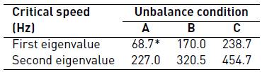
On the other hand, the modeling of the phenomena of unbalanced rotor by mean of transfer matrix method, registers that the eigenvalues of the system (lateral critical speeds) are very sensitive to the specific imbalances induced in the rotor. In Table 5, the results obtained by the mathematical model are summarized. If the imbalance in the rotor increases, then the frequencies at which the critical speeds appeared also rise, which is consistent with what was found by [13]. Note that due to limitations in the experimental installation, it was only possible to check the first critical speed for the condition of imbalance “A”.
4. Conclusions
The theoretical model obtained by the transfer matrix method allowed predicting the rotodynamic behavior of a multistage rotor. The theoretical model is simple and enables to include mass imbalance in the impellers, also to define stiffness and damping properties for the different components of the rotor. The theoretical results for the first two critical speeds (without mass imbalance for the rotor) shown a difference of -6.76% and -12.65% respectively compared to the results obtained by the experimental model. This model has good accuracy for practical purposes.
An increase in the mass imbalance for the rotor leads to a rise of the two first lateral critical speeds. For example, the first two lateral critical speeds obtained with the theoretical model for the unbalance condition “A”, increased from 42.9 Hz and 85.6 Hz to 68.7 Hz and 227.0 Hz respectively. This was confirmed experimentally for the first experimental test of imbalance (condition “A”), proving that the first critical speed is like that determined by the mathematical theoretical model. It was not possible to record this behavior experimentally for higher critical frequency values due to technical limitations of the physical model. Furthermore, the vibration level recorded in the physical model rises 2.5 times when the multistage rotor approaches to the first two critical speeds.
The novel experimental facility developed allows a wide range of operating conditions for tests. In future work, other cases of imbalanced rotor conditions should be developed, to find a correlation between the quantity of mass imbalance and the critical speeds experienced by the multistage rotor.

